1
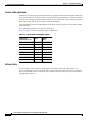
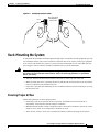
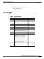
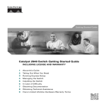
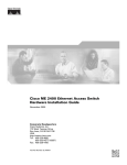
C H A P T E R
2
Preparing for Installation
This chapter describes the safety instructions and site requirements needed for installing the IE2100
Series device and guides you through installation preparation. It contains information about:
•
Safety
•
Preparing Your Site for Installation
•
Rack-Mounting the System
•
Required Tools and Equipment
Safety
This section provides safety information for installing this product.
Warnings and Cautions
Note
Read the installation instructions in “Installing and Configuring the IE2100 Series” before you
connect the system to its power source because you must be extremely careful when installing
electrical devices. Failure to read and follow these guidelines could lead to an unsuccessful
installation and possible damage to the system and components.
You should observe the following safety guidelines when working with any equipment that connects to
electrical power or telephone wiring. They can help you avoid injuring yourself and damaging the
IE2100 Series.
The following warnings and cautions are provided to help you prevent damage to the devices or injury
to yourself:
Warning
The safety cover is an integral part of the product. Do not operate the unit without the safety cover
installed. Operating the unit without the cover in place will invalidate the safety approvals and
pose a risk of fire and electrical hazards.
Cisco Intelligence Engine 2100 Series Configuration Registrar Manual
OL-1570-01
2-1
Chapter 2
Preparing for Installation
Safety
Warning
Never defeat the ground conductor or operate the equipment in the absence of a suitably installed
ground conductor. Contact the appropriate electrical inspection authority or an electrician if you
are uncertain that suitable grounding is available.
Warning
Before working on a chassis or working near power supplies, unplug the power cord on AC units;
disconnect the power at the circuit breaker on DC units.
Warning
Only trained and qualified personnel should be allowed to install, replace, or service this
equipment.
Warning
This product relies on the building’s installation for short-circuit (overcurrent) protection. Make
sure that a fuse or circuit breaker no larger than 120 VAC, 15A U.S. and 240 VAC, 10A international
are used on the phase conductors (all current-carrying conductors).
Warning
This equipment is intended to be grounded. Ensure that the host is connected to earth ground
during normal use.
Warning
Do not work on the system or connect or disconnect cables during periods of lightning activity.
Warning
Before working on equipment that is connected to power lines, remove jewelry (including rings,
necklaces, and watches). Metal objects will heat up when connected to power and ground and
can cause serious burns or weld the metal object to the terminals.
Warning
Ultimate disposal of this product should be handled according to all national laws and
regulations.
Warning
Before working on a system that has an On/Off switch, turn OFF the power and unplug the power
cord.
Warning
Read the installation instructions before you connect the system to its power source.
Warning
The device is designed to work with TN power systems.
Cisco Intelligence Engine 2100 Series Configuration Registrar Manual
2-2
OL-1570-01
Chapter 2
Preparing for Installation
Safety
Warning
The ports labeled “10BaseT”, “100BaseTX”, and “10/100” are safety extra-low voltage (SELV)
circuits. SELV circuits should only be connected to other SELV circuits. Avoid connecting these
circuits to telephone network voltage (TNV) circuits.
Warning
There is the danger of explosion if the battery is replaced incorrectly. Replace the battery only
with the same or equivalent type recommended by the manufacturer. Dispose of used batteries
according to the manufacturer’s instructions.
Working with Electricity
Follow these guidelines when working on electrical equipment:
•
Locate the emergency power-off switch for the room in which you are working. If an electrical
accident occurs, you can act quickly to turn off the system.
•
Disconnect all power by powering off the system and unplugging the power cord before:
– Installing or removing a chassis
– Working near power supplies
•
Do not work alone if potentially hazardous conditions exist.
•
Never assume that power is disconnected from a circuit; always check the circuit.
•
Look carefully for possible hazards in your work area, such as moist floors, underground power
extension cables, frayed power cords, and missing safety grounds
•
If an electrical accident occurs:
– Use caution: do not become a victim yourself.
– Power off the system.
– If possible, send another person to get medical aid. Otherwise, assess the victim’s condition,
then call for help.
– Determine if the person needs rescue breathing or external cardiac compressions; then take
appropriate action.
•
Disconnect all power and external cables before installing or removing a chassis.
•
Never install equipment that appears damaged.
•
Never install telephone wiring during a lightning storm.
•
Never install telephone jacks in wet locations unless the jack is specifically designed for wet
locations.
•
Never touch uninsulated telephone wires or terminals unless the telephone line has been
disconnected at the network interface.
•
Always use caution when installing or modifying telephone lines.
•
Never perform any action that creates a potential hazard to people or makes the equipment unsafe.
Cisco Intelligence Engine 2100 Series Configuration Registrar Manual
OL-1570-01
2-3
Chapter 2
Preparing for Installation
Preparing Your Site for Installation
Preventing Damage from Electrostatic Discharge
Electrostatic discharge (ESD) can damage equipment and impair electrical circuitry. ESD damage occurs
when electronic components are handled improperly and can result in complete or intermittent failures.
•
Always follow ESD-prevention procedures when removing and replacing components. Verify that
the chassis is electrically connected to earth ground. Wear an ESD-preventive wrist strap, making
sure that it makes good skin contact. Connect the grounding clip to an unpainted surface of the
chassis frame to safely ground ESD voltages. To properly guard against ESD damage and shocks,
the wrist strap and cord must operate effectively. If no wrist strap is available, ground yourself by
touching the metal part of the chassis.
•
Periodically check the resistance value of the antistatic strap, which should be between 1 and 10
Mohms.
Preventing EMI
When you run wires for any significant distance in an electromagnetic field, electromagnetic interference
(EMI) can occur between the field and the signals on the wires.
Note that:
•
Bad plant wiring can result in radio frequency interference (RFI).
•
Strong EMI, especially when it is caused by lightning or radio transmitters, can destroy the signal
drivers and receivers in the system, and can even create an electrical hazard by conducting power
surges through lines and into the system.
To predict and remedy strong EMI, consult RFI experts.
Covering Empty Slots
Ensure that all cards, faceplates, and covers are in place. Blank faceplates and cover panels are used to:
•
Prevent exposure to voltages and currents inside the chassis.
•
Help contain electromagnetic interference (EMI) that might disrupt other equipment.
•
Direct the flow of cooling air through the chassis.
Preparing Your Site for Installation
Make sure your site is prepared properly before beginning installation.
Environmental
When planning your site layout and equipment locations, keep in mind the precautions described in this
section to help avoid equipment failures and reduce the possibility of environmentally caused
shutdowns. If you are currently experiencing shutdowns or unusually high errors with your existing
equipment, these precautions will help you isolate the cause of failures and prevent future problems.
Use the following precautions when planning the operating environment for your IE2100 Series.
Cisco Intelligence Engine 2100 Series Configuration Registrar Manual
2-4
OL-1570-01
Chapter 2
Preparing for Installation
Preparing Your Site for Installation
•
Always follow the ESD-prevention procedures described in the section “Preventing Damage from
Electrostatic Discharge” to avoid damage to equipment. Damage from static discharge can cause
immediate or intermittent equipment failure.
•
Make sure the chassis cover is secure. The chassis is designed to allow cooling air to flow effectively
within it. An open chassis allows air leaks, which could interrupt and redirect the flow of cooling air
from internal components.
•
Electrical equipment generates hear. Ambient air temperature might not be adequate to cool
equipment to acceptable operating temperatures without adequate circulation. Make sure that the
room in which you operate has adequate air circulation.
Choosing a Site For Installation
Warning
This unit is intended for installation in restricted access areas. A restricted access area is where
access can only be gained by service personnel through the use of a special tool, lock and key, or
other means of security, and is controlled by the authority responsible for the location.
•
Choose a site with a dry, clean, well-ventilated and air-conditioned area.
•
Choose a site that maintains an ambient temperature of 32 to 104 degrees F (0 to 40 degrees C).
Grounding the System
Warning
Never defeat the ground conductor or operate the equipment in the absence of a suitably installed
ground conductor. Contact the appropriate electrical inspection authority or an electrician if you
are uncertain that suitable grounding is available.
Creating a Safe Environment
Follow these guidelines to create a safe operating environment:
•
Keep tools and chassis components off the floor and away from foot traffic.
•
Clear the area of possible hazards, such as moist floors, ungrounded power extension cables, and
missing safety grounds.
•
Keep the area around the chassis free from dust and foreign conductive material (such as metal
flakes from nearby construction activity).
Cisco Intelligence Engine 2100 Series Configuration Registrar Manual
OL-1570-01
2-5
Chapter 2
Preparing for Installation
Preparing Your Site for Installation
AC Power
•
The system is designed for connection to TN power systems. A TN power system is a power
distribution system with one point connected directly to earth (ground). The exposed conductive
parts of the installation are connected to that point by protective earth conductors.
•
Ensure that the plug-socket combination is accessible at all times, because it serves as the main
disconnecting device.
The IE2100 Series has the following power requirements:
•
Universal input: 100-127/200-240 VAC
•
Frequency: 50-60HZ
•
Maximum power: 65 watts
Warning
This product relies on the building’s installation for short-circuit (overcurrent) protection. Make
sure that a fuse or circuit breaker no larger than 120 VAC, 15A U.S. and 240 VAC, 10A international
are used on the phase conductors (all current-carrying conductors).
Warning
The device is designed to work with TN power systems.
Cabling
Use the cables in the accessory kit to connect the IE2100 Series console port to a console or computer
that is running a console program. In addition to the console cable, you must supply your own standard
Ethernet cable to connect the IE2100 Series to your network. This section details the pinout information
for these cables, so that you can purchase the correct cable for your network connection, and replace the
console cable and adapters if that becomes necessary.
A structured wiring system provides a standardized way to wire a building for all types of networks for
the IE2100 Series appliance to be installed. The main distribution frame links all the building’s interior
wiring and provides an interface connection to circuits coming from outside sources such as the local
telephone company. Wiring hubs (peripherals for cabling installations) provide the connection logic
unique to Fast Ethernet cables that the IE2100 Series uses. Unshielded twisted pair (UTP) copper wire
is used to connect the IE2100 Series and distributes the network connections to wall jacks near each
piece of network equipment.
Warning
The ports labeled “10BaseT”, “100BaseTX”, and “10/100” are safety extra-low voltage (SELV)
circuits. SELV circuits should only be connected to other SELV circuits. Avoid connecting these
circuits to telephone network voltage (TNV) circuits.
Ethernet Standards
To connect the IE2100 Series to your network, you must use one of the following Fast Ethernet cables:
•
An RJ-45 to RJ-45 straight-through cable to connect the IE2100 Series to a hub
•
An RJ-45 to RJ-45 crossover cable to connect the IE2100 Series to another device
Cisco Intelligence Engine 2100 Series Configuration Registrar Manual
2-6
OL-1570-01
Chapter 2
Preparing for Installation
Preparing Your Site for Installation
The Ethernet configuration using unshielded twisted pair (UTP) wire is known as 10BaseT because it
uses 10 megabits per second (Mbps) signaling speed, direct current, or baseband, signaling, and twisted
pair wire.This configuration includes a central wiring hub with special circuitry to isolate
malfunctioning segments of the network. UTP wire uses an RJ-45 connector at each end of the wire. New
signaling schemes such as 100BaseT and gigabit Ethernet use the same UTP cabling with upgraded hubs
and adapters.
Use a CAT 5 UTP cable at minimum to connect to a 100BaseT network. Use a CAT 3 UTP cable at
minimum to connect to a 10BaseT network.
Table 2-1 on page 2-7 shows the pinouts for a straight-through 100BaseT cable.
Table 2-1
Straight-Through 100BaseT Cable (RJ-45 to RJ-45) Pinouts
RJ-45 Pin
Signal
Direction
RJ-45 Pin
1
TX+
—>
1
2
TX-
—>
2
3
RX+
<—
3
4
—
—
4
5
—
—
5
6
RX-
<—
6
7
—
—
7
8
—
—
8
Table 2-2 shows the pinouts for a crossover 100BaseT cable.
Table 2-2
Crossed-Over 100BaseT Cable (RJ-45 to RJ-45) Pinouts
RJ-45 Pin
Signal
Direction
RJ-45 Pin
1
TX+
—>
3
2
TX-
—>
6
3
RX+
<—
1
4
—
—
4
5
—
—
5
6
RX-
<—
2
7
—
—
7
8
—
—
8
Cisco Intelligence Engine 2100 Series Configuration Registrar Manual
OL-1570-01
2-7
Chapter 2
Preparing for Installation
Preparing Your Site for Installation
Console Cable and Adapter
The EIA/TIA-232 console port on the IE2100 Series is configured as data terminal equipment (DTE) and
uses an RJ-45 connector. A console cable kit is provided with your IE2100 Series to connect an ASCII
terminal or a PC running terminal emulation software to the console port. The kit contains an RJ-45 to
RJ-45 rollover cable and one RJ-45 to DB-9 female DTE adapters.
You can attach the two RJ-45 to DB-9 adapters to the RJ-45 to RJ-45 rollover to create a DB-9 to DB-9
null-modem cable.
The communication parameters are based on 9600-N-8-1.
Table 2-3 on page 2-8 shows the pinouts for this configuration.
Table 2-3
Console Cable and Adapters Pinouts
IE2100 Series
Console Port (RJ-45)
Signal
Terminal
(DB-9)
1
RTS
7
2
DTR
4
3
TxD
3
4
GND
5
5
GND
5
6
RxD
2
7
DSR
6
8
CTS
8
Rollover Cable
You can identify a rollover cable by comparing the two modular ends of the cable (Figure 2-1 on
page 2-9). Holding the cables in your hand, side-by-side, with the tab at the back, the wire connected to
the pin on the outside of the left connector (pin 1) should be the same color as the pin on the outside of
the right connector (pin 8).
Cisco Intelligence Engine 2100 Series Configuration Registrar Manual
2-8
OL-1570-01
Chapter 2
Preparing for Installation
Rack-Mounting the System
Figure 2-1
Identifying a Rollover Cable
Pin 8
49339
Pin 1
Pin 1 and pin 8
should be the
same color
Rack-Mounting the System
A rack-mount kit is included for mounting the IE2100 Series in a standard 19-inch equipment rack with
two unobstructed outer posts. This kit cannot be used with other racks, such as a telco-type equipment
rack, or those with obstructions (such as a power strip) that could impair access to the hard disk and
power supplies. Allow sufficient clearance around the rack for system maintenance.
Warning
To prevent bodily injury when mounting or servicing this unit in a rack, you must take special
precautions to ensure that the system remains stable. The following guidelines are provided to
ensure your safety:
•
This unit should be mounted at the bottom of the rack if it is the only unit in the rack.
•
When mounting this unit in a partially filled rack, load the rack from the bottom to the top with the
heaviest component at the bottom of the rack.
•
If the rack is provided with stabilizing devices, install the stabilizers before mounting or servicing
the unit in the rack.
Ensuring Proper Airflow
Follow these guidelines to ensure proper airflow:
•
Install the system in an open rack whenever possible. If installation in an enclosed rack is
unavoidable, ensure that the rack has adequate ventilation.
•
Maintain ambient airflow to ensure normal operation. If the airflow is blocked or restricted, or if the
intake air is too warm, an overtemperature condition can occur.
•
Allow at least 6 inches (15.24 cm) of clearance around the ventilation openings of the chassis.
Cisco Intelligence Engine 2100 Series Configuration Registrar Manual
OL-1570-01
2-9
Chapter 2
Preparing for Installation
Required Tools and Equipment
•
Avoid placing the system in an overly congested rack or directly next to another equipment rack.
Heat exhaust from other equipment can enter the inlet air vents and cause an overtemperature
condition.
•
Equipment near the bottom of a rack might generate excessive heat that is drawn upward and into
the intake ports of the equipment above. The warm air can cause an overtemperature condition in
the equipment above.
•
Ensure that cables from other equipment do not obstruct the airflow through the chassis or impair
access to the power supplies or cards. Route cables away from field-replaceable components to
avoid disconnecting cables unnecessarily for equipment maintenance or upgrades.
Stabilizing the System
Follow these guidelines to stabilize the equipment rack:
•
Install any stabilizers that came with your equipment rack before mounting or servicing the system
in the rack.
•
Load the rack from the bottom to the top, with the heaviest system at the bottom.
•
Do not stack the system on top of any other equipment. If the system falls, it can cause severe bodily
injury and damage the equipment.
•
If you are using an equipment shelf, ensure that the shelf is constructed to support the weight and
dimensions of the chassis.
•
If you are using a telco rack, ensure that the weight of the chassis does not make the rack unstable.
Secure the telco rack with ceiling brackets if the rack is populated with heavy equipment.
•
Bolt the rack to the floor for stability.
Lifting the System
Follow these guidelines when lifting the system:
•
Disconnect all power and external cables before lifting the system.
•
Ensure that your footing is solid and the weight of the system is evenly distributed between your
feet.
•
Lift the system slowly, keeping your back straight. Lift with your legs, not with your back. Bend at
the knees, not at the waist.
Required Tools and Equipment
You need the following tools and equipment to install the system:
•
The provided accessory kit, which includes:
– Rack-mount kit
– Console cable
– Power cord
•
Antistatic mat or antistatic foam
•
ESD grounding strap
Cisco Intelligence Engine 2100 Series Configuration Registrar Manual
2-10
OL-1570-01
Chapter 2
Preparing for Installation
Accessory Kit
•
Ethernet cables
•
If you are installing the chassis in a rack, you need:
– Number 2 Phillips screwdriver
– Tape measure and level
Accessory Kit
Table 2-4 is a checklist of the contents of the accessory kit provided with the system.
Table 2-4
Accessory Kit Checklist
Quantity
Part Description
Received
2
L mounting brackets (left and right)
4
M4 Phillips countersunk-head screws
4
12-24 x 3/4-inch Phillips binder-head
screws
4
10-32 x 3/4-inch slotted binder-head screws
1
8-32 x1-1/2-inch black Phillips binder-head
screw
4
Desktop mounting self-adhesive feet
1
Rack-mounting cable guide
1
DB9 to RJ45 adaptor for attaching the
console serial cable to a 9-pin serial port.
1
Console serial cable
1
Ethernet cable
1
Shrink wrapped package of documentation,
including the Cisco Documentation
CD-ROM, Cisco Information Packet
document, Release Notes for Cisco
Intelligence Engine 2100 Series,
Regulatory Compliance and Safety
Information for Cisco Intelligence Engine
2100 Series, and Cisco Intelligence Engine
2100 Series Quick Start Guide.
1
CD-ROM: CNSIE-2105 v 1.1 containing
the product software image.
1
Power cable
Cisco Intelligence Engine 2100 Series Configuration Registrar Manual
OL-1570-01
2-11
Chapter 2
Preparing for Installation
Accessory Kit
Cisco Intelligence Engine 2100 Series Configuration Registrar Manual
2-12
OL-1570-01