1
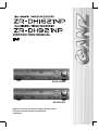
INSTRUCTION MANUAL
ZR-DH1621NP
ZR-DH921NP
Before connecting, operating or adjusting this product,
read this instruction booklet carefully and
completely.
© CBC Co., Ltd. All rights reserved.
Second Edition (September 2005)
COPYRIGHT
No part of this document may be reproduced or distributed in any form or by any means without
the express written permission of CBC Co., Ltd. (hereafter ‘CBC’).
TRADEMARKS
GANZ is a registered trademark of CBC Co., Ltd.
ii
CAUTION
RISK OF ELECTRIC SHOCK DO
NOT OPEN
CAUTION: TO REDUCE THE RISK OF ELECTRIC
SHOCK, DO NOT REMOVE COVER (OR BACK);
NO USER-SERVICEABLE PARTS INSIDE
REFER SERVICING TO QUALIFIED SERVICE
PERSONNEL.
Graphic Symbol Explanation
This lightning flash with arrowhead symbol within an equilateral triangle is intended to alert
the user to the presence of uninsulated dangerous voltage within the product’s enclosure
that may be of sufficient magnitude to constitute a risk of electric shock to persons.
The exclamation point within an equilateral triangle is intended to alert the user to the
presence of important operating and maintenance (servicing) instructions in the literature
accompanying the product.
This product is manufactured to comply with the radio interference
requirements of EEC DIRECTIVE 89/336/EEC, 93/68/EEC and 73/23/EEC.
THIS DEVICE COMPLIES WITH PART 15 OF THE FCC RULES. OPERATION IS SUBJECT TO THE
FOLLOWING TWO CONDITIONS: (1) THIS DEVICE MAY NOT CAUSE HARMFUL INTERFERENCE,
AND (2) THIS DEVICE MUST ACCEPT ANY INTERFERENCE RECEIVED, INCLUDING INTERFERENCE
THAT MAY CAUSE UNDESIRED OPERATION.
This equipment has been tested and found to comply with the limit for a Class A digital device, pursuant to
part 15 of the FCC Rules. These limits are designed to provide reasonable protection against harmful
commercial environment. This equipment generates, uses, and can radiate radio frequency energy and,
if not installed and used in accordance with the instruction manual, may cause harmful interface to radio
communications.
Operation of this equipment in a residential area is likely to cause harmful interface in which case
the user will be required to correct the interface at his own expense.
Warning
TO PREVENT FIRE OR SHOCK HAZARDS, DO NOT EXPOSE THIS PRODUCT TO RAIN OR MOISTURE.
Apparatus shall not be exposed to dripping or splashing and no object filled with liquids, such as vases, shall
be placed on the apparatus.
Wiring methods shall be in accordance with the National Electric Code, ANSI/NFPA 70.
iii
IMPORTANT SAFETY INSTRUCTIONS
CAUTION: PLEASE READ AND OBSERVE ALL WARNINGS AND INSTRUCTIONS IN THIS INSTALLATION AND
OPERATING GUIDE AND THOSE MARKED ON THE UNIT. RETAIN THIS GUIDE FOR FUTURE
REFERENCE.
This set has been designed and manufactured to assure personal safety. Improper use can result in electric shock
or fire hazard. The safeguards incorporated in this unit will protect you if you observe the following procedures for
installation, use, and servicing. This unit does not contain any parts that can be repaired by the user.
DO NOT REMOVE THE CABINET COVER, OR YOU MAY BE EXPOSED TO DANGEROUS VOLTAGE. REFER
SERVICING TO QUALIFIED SERVICE PERSONNEL ONLY.
1. Read these instructions. - All these safety and
operating instructions should be read before the
product is operated.
2. Keep these instructions. - The safety, operating and
use instructions should be retained for future reference.
3. Heed all warnings. - All warnings on the product and
in the operating instructions should be adhered to.
4. Follow all instructions. - All operating and usage
instructions should be followed.
5. Do not use this apparatus near water. – For
example: near a bath tub, wash bowl, kitchen sink,
laundry tub, in a wet basement; near a swimming pool;
etc.
blades with one wider than the other. A grounding
type plug has two blades and a third grounding
prong. The wide blade or the third prong are
provided for your safety. If the provided plug does
not fit into your outlet, consult an electrician for
replacement of the obsolete outlet.
10. Protect the power cord from being walked on or
pinched particularly at plugs, convenience
receptacles, and the point where they exit from the
apparatus.
11. Only use attachments/accessories specified by
the manufacturer.
6. Clean only with dry cloth. – Unplug this product from
the wall outlet before cleaning. Do not use liquid
cleaners.
7. Do not block any ventilation openings. Install in
accordance with the manufacturer’s instructions. Slots and openings in the cabinet are provided for
ventilation, to ensure reliable operation of the product,
and to protect it from over- heating. The openings
should never be blocked by placing the product on a
bed, sofa, rug or other similar surface. This product
should not be placed in a built-in installation such as a
bookcase or rack unless proper ventilation is provided
and the manufacturer’s instructions have been adhered
to.
8. Do not install near any heat sources such as
radiators, heat registers, stoves, or other apparatus
(including amplifiers) that produce heat.
9. Do not defeat the safety purpose of the polarized
or grounding-type plug. A polarized plug has two
FCC Warning
This equipment may generate or use radio frequency
energy. Changes or modifications to this equipment
may cause harmful interference unless the
modifications are expressly approved in the instruction
manual. The user could lose the authority to operate
this equipment if an unauthorized change or
modification is made.
iv
12. Use only the cart, stand, tripod, bracket, or table
specified by the manufacturer, or sold with
apparatus. When a cart is used, use caution when
moving the cart/ apparatus combination to avoid
injury from tip-over.
13. Unplug this apparatus during lightning storms or
when unused for long periods of time.
14. Refer all servicing to qualified service personnel.
Servicing is required when the apparatus has
been damaged in any way, such as powersupply cord or plug is damaged, liquid has been
spilled or objects have fallen into the apparatus,
the apparatus has been exposed to rain or
moisture, does not operate normally, or has been
dropped.
CE Warning
This is a Class A product. In a domestic environment
this may cause radio interference in which
case the user may be required to take adequate
measures.
The apparatus shall not be exposed to dripping or
splashing and no objects filled with liquids, such as
vases, shall be placed on the apparatus.
WARNING
Pay attention to the following information before installing the GANZ
ZR-DH1621NP/ZR-DH921NP.
• Keep the product away from heat. Do not expose the product directly to the sun or heating
apparatus. (becomes a fire hazard)
• Do not leave vessels with water such as a vase, a flowerpot, a cup, which may cause fire or
electric shock.
• Do not insert or put metallic material (coin, hair pin, metal) or flammable materials (paper,
matches) through vent holes.
• Do not place heavy objects on the product.
• Disconnect from power source during a thunder storm.
• Do not use chemicals or detergent to clean the product. Use a dry cloth.
• Discontinue using if there is strange odor or smoke. Power off and call for service.
• Do not touch the power plug with wet hands.
• Do not pull on the power cord.
• Do not twist the power cord. It may cause a fire or electric shock.
• Use an exclusive outlet. (Overloading the outlet may cause a fire or electric shock.)
• Do not expose to rain, extremely humid or dusty environments.
• Do not open the cover of the product.
• Do not place this product on an unstable shelf, cart, stand or tripod. The product may fall,
causing serious injury and damage to the product.
• Do not place heavy items on the power cord.
(It may cause a fire or electric shock.)
• Do not use multi outlet with any other devices. (It may cause a fire because the outlet is
overloaded.)
• When disconnecting the power plug, do not pull it by the cord. Doing so may damage the cord
causing electric shock or fire.
• Power cords should be routed so that they are not likely to be walked on or pinched by items
placed upon or against them.
• Do not touch the power adapter or signal processor with wet hand. (It may cause electric
shock.)
• This product generates, uses and can radiate radio frequency energy. If not installed and used
in accordance with the instruction manual it may cause radio communication interference.
• Do not block any vents. It may cause the fan to stop and damage the product.
v
vi
Contents
1 Parts and Features . . . . . . . . . . . . . . . . . . . . . . . . .1
1. 1 DVR System and Accessories . . . . . . . . . . . . . . . . . . . . . . . . . . . . . . .1
1. 2 Features . . . . . . . . . . . . . . . . . . . . . . . . . . . . . . . . . . . . . . . . . . . . . . . . .2
1. 3 Parts name and Description . . . . . . . . . . . . . . . . . . . . . . . . . . . . . . . .3
2 Setup and Connections . . . . . . . . . . . . . . . . . . . . .7
2. 1 Power Setup . . . . . . . . . . . . . . . . . . . . . . . . . . . . . . . . . . . . . . . . . . . . .7
2. 2 Telemetry Connection . . . . . . . . . . . . . . . . . . . . . . . . . . . . . . . . . . . . .7
2. 2. 1 PORT A RS-422 . . . . . . . . . . . . . . . . . . . . . . . . . . . . . . . . . . . . . . .7
2. 2. 2 PORT B RS-422/RS-485 . . . . . . . . . . . . . . . . . . . . . . . . . . . . . . . .7
2. 3 Alarm Connections . . . . . . . . . . . . . . . . . . . . . . . . . . . . . . . . . . . . . . . .8
2. 3. 1 ALARM INPUT . . . . . . . . . . . . . . . . . . . . . . . . . . . . . . . . . . . . . . . .8
2. 3. 2 ALARM OUTPUT . . . . . . . . . . . . . . . . . . . . . . . . . . . . . . . . . . . . . .8
2. 4 External Storage . . . . . . . . . . . . . . . . . . . . . . . . . . . . . . . . . . . . . . . . . .9
2. 4. 1 Using USB memory device . . . . . . . . . . . . . . . . . . . . . . . . . . . . . .9
2. 4. 2 Connecting CD-R/RW & HDD via USB . . . . . . . . . . . . . . . . . . . . .9
2. 4. 3 Connecting IEEE1394 (FireWire) devices . . . . . . . . . . . . . . . . . . .9
2. 5 Connecting to LAN or Internet . . . . . . . . . . . . . . . . . . . . . . . . . . . . . .9
2. 5. 1 Making physical connection . . . . . . . . . . . . . . . . . . . . . . . . . . . . . .9
2. 5. 2 Automatic network configuration . . . . . . . . . . . . . . . . . . . . . . . . . .9
2. 5. 3 Manually configure network . . . . . . . . . . . . . . . . . . . . . . . . . . . . . .9
3 Menu Configuration . . . . . . . . . . . . . . . . . . . . . . .11
3. 1 Camera Setup . . . . . . . . . . . . . . . . . . . . . . . . . . . . . . . . . . . . . . . . . . .11
3. 1. 1 Channel Setup . . . . . . . . . . . . . . . . . . . . . . . . . . . . . . . . . . . . . . .11
3. 1. 2 PTZ Model . . . . . . . . . . . . . . . . . . . . . . . . . . . . . . . . . . . . . . . . . .11
3. 1. 3 Video Format . . . . . . . . . . . . . . . . . . . . . . . . . . . . . . . . . . . . . . . .12
3. 2 Recording Setup . . . . . . . . . . . . . . . . . . . . . . . . . . . . . . . . . . . . . . . . .12
3. 2. 1 Schedule . . . . . . . . . . . . . . . . . . . . . . . . . . . . . . . . . . . . . . . . . . . .12
3. 2. 2 Specific Dates Schedule . . . . . . . . . . . . . . . . . . . . . . . . . . . . . . .14
3. 2. 3 Manual Recording . . . . . . . . . . . . . . . . . . . . . . . . . . . . . . . . . . . .14
3. 3 Alarm Setup . . . . . . . . . . . . . . . . . . . . . . . . . . . . . . . . . . . . . . . . . . . . .15
3. 3. 1 Alarm Outputs . . . . . . . . . . . . . . . . . . . . . . . . . . . . . . . . . . . . . . . .15
3. 3. 2 Event . . . . . . . . . . . . . . . . . . . . . . . . . . . . . . . . . . . . . . . . . . . . . .15
3. 3. 3 Alarm Name . . . . . . . . . . . . . . . . . . . . . . . . . . . . . . . . . . . . . . . . .15
3. 3. 4 Alarm Buzzer . . . . . . . . . . . . . . . . . . . . . . . . . . . . . . . . . . . . . . . .15
vii
3. 4 Display Setup . . . . . . . . . . . . . . . . . . . . . . . . . . . . . . . . . . . . . . . . . . .16
3. 4. 1 User Defined Screen . . . . . . . . . . . . . . . . . . . . . . . . . . . . . . . . . .16
3. 4. 2 Sequence . . . . . . . . . . . . . . . . . . . . . . . . . . . . . . . . . . . . . . . . . . .16
3. 4. 3 Spot Monitor . . . . . . . . . . . . . . . . . . . . . . . . . . . . . . . . . . . . . . . . .16
3. 4. 4 Transparency . . . . . . . . . . . . . . . . . . . . . . . . . . . . . . . . . . . . . . . .17
3. 5 Audio Setup . . . . . . . . . . . . . . . . . . . . . . . . . . . . . . . . . . . . . . . . . . . . .17
3. 6 Administration . . . . . . . . . . . . . . . . . . . . . . . . . . . . . . . . . . . . . . . . . .17
3. 6. 1 Language . . . . . . . . . . . . . . . . . . . . . . . . . . . . . . . . . . . . . . . . . . .17
3. 6. 2 HDD Management . . . . . . . . . . . . . . . . . . . . . . . . . . . . . . . . . . . .18
3. 6. 3 Network Setup . . . . . . . . . . . . . . . . . . . . . . . . . . . . . . . . . . . . . . .19
3. 6. 4 Date/Time Setup . . . . . . . . . . . . . . . . . . . . . . . . . . . . . . . . . . . . . .19
3. 6. 5 Password Administration . . . . . . . . . . . . . . . . . . . . . . . . . . . . . . .20
3. 6. 6 Firmware Management . . . . . . . . . . . . . . . . . . . . . . . . . . . . . . . .21
3. 6. 7 Covert Channel . . . . . . . . . . . . . . . . . . . . . . . . . . . . . . . . . . . . . .21
3. 6. 8 Mail Notification . . . . . . . . . . . . . . . . . . . . . . . . . . . . . . . . . . . . . .21
3. 6. 9 Configuration Management . . . . . . . . . . . . . . . . . . . . . . . . . . . . .22
3. 6. 10 Telemetry Control . . . . . . . . . . . . . . . . . . . . . . . . . . . . . . . . . . . .24
3. 6. 11 System Information . . . . . . . . . . . . . . . . . . . . . . . . . . . . . . . . . . .24
3. 7 Backup . . . . . . . . . . . . . . . . . . . . . . . . . . . . . . . . . . . . . . . . . . . . . . . . .24
3. 8 Event Log . . . . . . . . . . . . . . . . . . . . . . . . . . . . . . . . . . . . . . . . . . . . . .25
3. 9 Power . . . . . . . . . . . . . . . . . . . . . . . . . . . . . . . . . . . . . . . . . . . . . . . . . .25
3. 10 Lock Front Panel . . . . . . . . . . . . . . . . . . . . . . . . . . . . . . . . . . . . . . .25
4 Monitoring and Playback . . . . . . . . . . . . . . . . . . .27
4.
4.
4.
4.
1 On-Screen Display . . . . . . . . . . . . . . . . . . . . . . . . . . . . . . . . . . . . . . .27
2 Playback . . . . . . . . . . . . . . . . . . . . . . . . . . . . . . . . . . . . . . . . . . . . . . .27
3 Search Playback . . . . . . . . . . . . . . . . . . . . . . . . . . . . . . . . . . . . . . . . .27
4 PTZ Mode . . . . . . . . . . . . . . . . . . . . . . . . . . . . . . . . . . . . . . . . . . . . . .27
4. 4. 1 Controlling PTZ Camera . . . . . . . . . . . . . . . . . . . . . . . . . . . . . . . .27
4. 4. 2 Using PTZ Presets . . . . . . . . . . . . . . . . . . . . . . . . . . . . . . . . . . . .27
4. 5 Remote Access . . . . . . . . . . . . . . . . . . . . . . . . . . . . . . . . . . . . . . . . . .28
4. 5. 1 Live Page . . . . . . . . . . . . . . . . . . . . . . . . . . . . . . . . . . . . . . . . . . .28
4. 5. 2 Playback Page . . . . . . . . . . . . . . . . . . . . . . . . . . . . . . . . . . . . . . .28
5 Troubleshooting . . . . . . . . . . . . . . . . . . . . . . . . . .29
Appendix A . . . . . . . . . . . . . . . . . . . . . . . . . . . . . . . .31
Factory Default Menu Settings . . . . . . . . . . . . . . . . . . . . . . . . . . . . . . . . .31
viii
Appendix B . . . . . . . . . . . . . . . . . . . . . . . . . . . . . . . .32
Recording Rate . . . . . . . . . . . . . . . . . . . . . . . . . . . . . . . . . . . . . . . . . . . . .32
Appendix C . . . . . . . . . . . . . . . . . . . . . . . . . . . . . . . .33
Recording Time . . . . . . . . . . . . . . . . . . . . . . . . . . . . . . . . . . . . . . . . . . . . .33
Appendix D . . . . . . . . . . . . . . . . . . . . . . . . . . . . . . . .37
Menu Tree . . . . . . . . . . . . . . . . . . . . . . . . . . . . . . . . . . . . . . . . . . . . . . . . . .37
Appendix E . . . . . . . . . . . . . . . . . . . . . . . . . . . . . . . .38
Specifications . . . . . . . . . . . . . . . . . . . . . . . . . . . . . . . . . . . . . . . . . . . . . . .38
ix
x
1 Parts and Features
1. 1 DVR System and Accessories
Appearance may vary.
ZR-DH1621NP
Rack Mount Brackets
ZR-DH921NP
RS-485/422 Terminal Block
CD-ROM
Alarm Out Terminal Block
Power Cord
Alarm In (2EA) Terminal Block
RJ-11 Cable &
Terminal Block
1
1. 2 Features
1) High quality digital recording
Record and playback High-Resolution
digital video by using Wavelet compression
and decompression circuitry.
2) Simple user interface
Simple operation by telemetry, integrated
buttons and jog shuttle/dial.
3) High reliability
Highly reliable due to a combination of
hardware quality and an embedded LINUX
based operating system.
4) Simple setting and system maintenance
Enables simple installation and operation
with basic settings and camera inputs.
5) Diverse total security function
Enables security system by using alarm
inputs, outputs and PTZ camera control.
6) Remote data backup
Backup and playback using client
application via network.
7) Large storage capacity
Storage can be extended through the use
of external IEEE 1394 and USB interfaces.
8) Local data backup
Back up image using USB memory devices
such as USB FDD, USB ZIP Drive.
9) Variety of monitoring functions
A variety of monitoring functions are possible,
such as FULL/PIP/4/6/8/9/13/16/user/ZOOM
(ZR-DH921NP : FULL/PIP/4/6/8/9/user/ZOOM)
screen. View live and playback simultaneously
while recording.
2
10) Audio recording playback function
Adjustable audio quality and compression
for added flexibility.
11) Motion detection and event recording
Digital motion detection and event
recording with pre and post alarm
recording.
12) Search Function
Playback quickly via diverse search
conditions and event log.
13) Firmware upgrade
Allows easy upgrade of product firmware
via the Internet or USB port.
14) Various recording resolution
Record up to 120FPS NTSC or 100FPS
PAL and 7 quality levels.
15) Simultaneous recording and playback
True triplex function allows for
simultaneous recording and playback
locally as well as via the network.
16) Multi password function
Allows 5 permission levels to control
access and operation.
17) Event Notification function
Notification via e-mail to monitor alarms as
well as various events and actions.
18) Camera control function
Allows PTZ camera control from the built-in
front panel keys.
1. 3 Parts name and Description
1
2
3
4
5
6
7
8
9
10
11 12 13
14
15
16
11 12 13
14
15
16
8
9
17
18
10
19
1) DISPLAY
Toggles between 1, 4, 9, 16, 6, 8 and 7 split
screens (ZR-DH921NP : 1, 4, 9, 6, 8 and 7 split
screens). Enter PTZ on-screen menu in PTZ
mode.
2) USER
Enter user defined screen mode. Use the
DISPLAY button to toggle between 4, 9, 6, 7, 10,
13, 8 and PIP screens. Enter detail view while in
Recording Schedule.
3) SPOT
Enter SPOT mode to allow SPOT monitor
control. When enabled the main monitor displays
the Spot status indicator.
4) FULL ZOOM
Allows 2, 3 or 4 times zooming. Use the
directional buttons to move the zoomed area.
5) PANORAMA
Playback a single channel on a multi-split
20
21
22
screen. Use the DISPLAY and channel buttons
to adjust the viewing effect.
6) PIP
Picture-in-Picture mode allows to view live and
playback screens simultaneously.
7) SEARCH
Playback by specific date and time or event.
8) Channels (1~16)
Select video channels (ZR-DH1621NP : 1~16 /
ZR-DH921NP : 1~9) in live, playback, PTZ and
menu modes. Buttons 1~10 (ZR-DH921NP :
Buttons 1~9) are used to enter password digits.
9) USB port
Used to connect HDD, CD writers and memory
devices.
10) LED Indicators
POWER/REC, HDD, LAN, MENU and PTZ
indicators.
3
11) MENU
Enter menu mode; exit sub-menus.
12) PTZ/ENTER
Enter PTZ mode; select or confirm menu
selection.
16) Jog Shuttle/Dial
Shuttle: Fast forward or rewind during
playback.
Dial: Slow forward/reverse playback in
pause.
13) STOP
Stops playback; reset alarms; hold down to
select multiple cells in Recording
Schedule.
14) R.PLAY, PLAY, FF, REW
R.PLAY: Reverse Playback/Left
PLAY: Playback/Right
FF: Fast Forward/Up
REW: Rewind/Down
Used to control Pan/Tilt
JOG DIAL
JOG SHUTTLE
17) AUTO
Sequences channels in live view mode;
enables auto focus in PTZ mode.
18) TOUR
Initiate PTZ tour.
19) PRESET
Setup PTZ preset positions.
15) PAUSE
Pause playback.
20) ZOOM/COPY
Adjust zoom position in PTZ mode; copy
image to USB device.
21) FOCUS
Adjust focus position in PTZ mode.
22) IRIS
Adjust Iris position in PTZ mode.
Mark Function : It is possible to set up the
section by using IRIS-(Mark In)/IRIS+
(Mark Out)button during playback.Setup
section can be back up by using Use Mark
during backup and possible to replay by
using Play Mark at the Search Menu.
4
REAR
1
2
3
4
5
6
7
8
9
10
7
8
9
10
13
12
1
2
3
11
4
5
6
12
14
11
13
14
1) PORT A (RS-422)
Used for communicating with external
devices in full-duplex RS-422.
7) IEEE 1394
Connect external IEEE 1394 devices
(FireWire) such as HDD and CD-RW.
2) LAN
10/100 Base-T ethernet connection.
8) MONITOR
Monitor output as composite signal.
3) PORT B (RS-422/RS-485)
Used for communicating with external
devices in full-duplex RS-422 or half-duplex
RS-485
9) SPOT OUT
Spot monitor output as composite signal.
4) ALARM IN
ZR-DH1621NP : 16 alarm inputs
ZR-DH921NP : 9 alarm inputs
5) ALARM OUT
4 alarm outputs.
6) S-VIDEO
Monitor output as S-VIDEO signal.
Notice
Connect and power IEEE 1394 devices prior
to powering DVR. Some devices may not be
recognized when both HDD and CD-R/RW
devices are present.
10) AUDIO IN/OUT
RCA terminals for audio recording and
playback.
11) POWER Switch
Main power switch.
12) VIDEO INPUT & LOOP OUT
(ZR-DH1621NP : 1~16 / ZR-DH921NP : 1~9)
Connect asynchronous video signal 1.0
Vp-p (75 ohm). Loop out is changed to
HI-Z automatically.
13) AC SELECT
Select AC115V or 230V.
14) AC INLET
Input power voltage.
5
6
2 Setup and Connections
2. 1 Power Setup
Select power (AC 115V/AC 230V) by AC
Selector according to input voltage.
• If set as figure 1, AC 115V is selected.
• If set as figure 2, AC 230V is selected.
2. 2 Telemetry Connection
Multiple DVRs and keypads may be
connected via RS-422 (PORT A). Up to two
PTZ serial communication lines are
supported via RS-485/422 (PORT A, PORT
1 & PORT 2).
2. 2. 1 PORT A RS-422
Figure 1
AC SELECT
115
There are two RJ-11 connections for PORT
A which can be used to “chain” the DVR with
other devices. The primary use of PORT A is
to interconnect two or more DVRs and/or
keypads (optional).
PORT A can also be used to connect PTZ
cameras by using the RJ-11 Terminal Block.
Figure 2
230
AC SELECT
Note
Even though there are two physical
connections PORT A is a single port
designed to connect multiple devices in
a single communication line.
2. 2. 2 PORT B RS-422/RS-485
PORT B is a 5-pin terminal connection. It
can be used as either a full-duplex RS-422
port or a half-duplex RS-485 port.
Use this port to connect PTZ cameras,
DVRs or keypads (optional).
7
2. 3 Alarm Connections
2. 3. 2 ALARM OUTPUT
Connect up to 4 separate alarms to the
Alarm Output.
2. 3. 1 ALARM INPUT
Connect up to 16 alarm sensors (ZRDH921NP : 9 alarm sensors) using the
supplied terminal blocks.
Alarm may be triggered by numerous events
including digital motion detection, Full Disk,
Signal Loss, Power Off, Network Access.
The signal state is adjustable to N/O
(Normaly Open) or N/C (Normaly Closed).
GND
1 2 3 4 5 6 7 8
GND
GND
9 10 11 12 13 14 15 16
GND
1
2
5
6
3
7
4
8
9
GND
1
2
3
4
ZR-DH1621NP
ZR-DH921NP
Notice
SW
SW
DC
GND
SENSOR IN
COMMON GND
Notice
Each ALARM IN should be connected
with GND which is grounded by TTL or
contact point. Components z
8
The internal switching relays are rated
for up to 24V at 1.0A maximum.
Damage may occur if current is
higher!
2. 4 External Storage
2. 4. 1 Using USB memory device
Insert the memory device into the USB port.
The system automatically recognizes the
device.
2. 4. 2 Connecting CD-R/RW & HDD via USB
Connect and power each USB device before
powering the DVR.
2. 4. 3 Connecting IEEE1394 (FireWire)
devices
Connect and power each device before
powering the DVR.
2. 5 Connecting to LAN or
Internet
2. 5. 1 Making physical connection
Connect the LAN port of the DVR to an
available 10/100 Base-T port with a straight
ethernet cable (not supplied). The link
indicator LED will be lit.
2. 5. 2 Automatic network configuration
The DVR can automatically obtain and
configure the network interface via DHCP.
Refer to page 19.
2. 5. 3 Manually configure network
The DVR may be manually configured by
assigning an IP address, subnet mask,
gateway DNS. Refer to page 19.
FireWire devices appear in
HDD Management as type 1394
Note
Up to 20 FireWire devices may be
connected in series.
9
10
3 Menu Configuration
The features and options of the DVR are
configured through the menu.
• Use the Jog Dial or directional buttons to
navigate through the menu.
Select this button to test the PTZ settings.
• Adjustment
Adjust the the brightness, contrast,
saturation and hue for this channel
• Press ENTER button to select or confirm.
• Press MENU button to return to previous
menu.
Current Channel
3. 1. 2 PTZ Model
The communication speed of each PTZ
model can be adjusted.
3. 1 Camera Setup
The video channels, PTZ and video format
settings are configured through the Camera
Setup menu.
• Select Model
Choose the PTZ model.
• Baud Rate
Choose the communication speed.
3. 1. 1 Channel Setup
Select the desired channel with the channel
button. Each video channel can be adjusted
independently.
• Name
Enter the Channel name up to 16
characters.
• Control ID, Reverse Pan, Reverse Tilt
If this channel is for a PTZ camera enter
the camera ID and pan/tilt directions.
• Model
If this channel is for a PTZ camera choose
the model.
• Control Test
A new PTZ model can be added to the
system if the protocol software is available.
An existing PTZ model can be deleted by
choosing the model and selecting the Delete
button.
11
3. 1. 3 Video Format
The DVR can support both NTSC and PAL
formats. This setting can be changed
through the Video Format menu.
The quality level (QL) can be adjusted for
each hour. The audio recording (AR) can
also be enabled or disabled.
The recording method (Continuous, Alarm,
Motion) for each block is shown in color for
easy viewing. The recording rate and
resolution are not shown. To see the detail
settings press the USER button.
To change the format select either NTSC or
PAL and press the MENU button. The
system will restart in the chosen format.
Important
Changing the format will initialize the
HDD storage and all data will be lost.
3. 2 Recording Setup
The DVR can record according to schedule
set by the user. It can also record manually
regardless of date and time. This is called
Manual Recording.
The detail screen shows 8 channels over a
6-hour period. Press the USER button again
to return to the summary view.
The recording can be made either
continuously or triggered by events (alarm
and motion detection).
The recording rate and resolution can be
adjusted for each recording defined in the
Schedule or Manual Recording.
The DVR is set to record in Schedule mode
from the factory with pre-defined schedule.
Thus it is always recording.
To stop recording the DVR must be put into
Manual Recording mode and recording
turned off.
3. 2. 1 Schedule
The Recording Schedule screen displays
one day of the week showing the schedule
of all channels over a 24-hour period.
For each 1-hour cell block the recording
method, rate and resolution can be specified.
12
• To edit one block
Move the highlighted cell block and press
the ENTER button.
• To edit multiple blocks
Move the highlighted cell block to one
corner of a rectangle area. Press and hold
the STOP button then expand the
highlighted area as desired. Press the
ENTER button.
Note
The image file size shown is average.
The actual size may vary.
To view and setup another day of the week
select the desired day as shown and press
the ENTER button.
Choose the recording methods, Field Rate
and Recording Resolution for the block(s).
Two settings can be specified: one for
continuous recording, the other for alarm and
motion recording.
• Field Rate
The available rate depends on the
resolution and the number of channels
being recorded. For most applications set
to Max.
• Resolution
Set the horizontal resolution to 720 or 360.
The copy function within the Schedule allows
copying the setting from one channel to
others. Once the recording schedule for an
entire day is complete it can be copied to
other days. To copy the channel or the day
select the Copy To button.
The quality level (QL) can be assigned to
each hour. The level ranges from 1 (low) to 7
(high). Low quality setting results in high
compression which takes less storage
space. High quality setting retains more
detail with lower compression but takes up
more space.
Quality
Level
Q7
Q6
Q5
Q4
Q3
Q2
Q1
Image File Size (KB)
720
360
18
11
17
10
15
9
13
8
10
6
7
5
5
3
To copy days select the day(s) of the week
and select the Copy button. For channels
select the source channel, select the
channel(s) to be copied then select the Copy
button.
13
3. 2. 2 Specific Dates Schedule
In addition to the weekly schedule, up to 16
specific date/time periods can be defined. To
configure the specific recording schedule
select Specific Dates.
3. 2. 3 Manual Recording
Use the Manual Recording method when the
recording does not depend on a schedule
(dates, days and time). To setup manual
recording, select Manual as the Record
Mode.
Time Estimation Function
• Add New Schedule
With the "Add" highlighted press the
ENTER button. Enable the schedule and
Specify the date/time period. Press the
MENU button when finished.
• Change Schedule
Define the recording setting for each
channel as well as the quality level and
audio.
• Delete Schedule
Highlight the "Delete" and press the
ENTER button.
14
It is set up at Recording Setup menu. It
indicates time that can be recorded at HDD
remained space
As checking overwrite function, it indicates
the whole of HDD space’s time to record.
Then define the record settings for each
channel within the Manual Recording screen.
3. 3 Alarm Setup
Within the Alarm Setup menu, alarm
conditions and events, as well as digital
motion detection settings are defined.
• Pre-Recording Time
Specify the time in 0 ~ 20 seconds.
• Post-Recording Time
Specify the time in 0 ~ 99 seconds.
3. 3. 1 Alarm Outputs
There are four alarm outputs. For each
output, define the alarm inputs and
conditions.
ZR-DH1621NP
ZR-DH921NP
For each channel, motion detection area and
sensitivity can be setup. Press the desired
channel button and define the settings.
• Full
Entire video screen is subject to motion
detection.
• Area
Motion is detected only in the area
specified.
Current Alarm Output
Alarm
Select the alarm input(s) to trigger this alarm
output.
• Event
Select events to trigger this alarm output.
•
• Alarm Off
Choose the way the alarm is reset. The
alarm can be reset automatically by
selecting Automatic and specifying the time
in seconds. If it is set to Manual the user
must press the STOP button.
The alarm state can be set to either N/O
(Normally Open) or N/C (Normally Closed).
3. 3. 2 Event
Pre- and post-alarm recording can be
defined in seconds.
• Sensitivity
Specify the motion sensitivity (1 ~ 30).
Higher the value, more sensitive the
motion detection is.
• Area Define
Select the motion sensing areas by
highlighting the 14 x 14 grid screen.
Use the directional buttons and press the
ENTER button.
3. 3. 3 Alarm Name
The alarm inputs can be named. Select the
alarm input and enter its name.
3. 3. 4 Alarm Buzzer
If enabled, when an alarm is triggered by the
alarm input or motion detection a buzzer will
sound. It can automatically clear after a
specified time.
15
3. 4 Display Setup
3. 4. 1 User Defined Screen
In addition to the pre-defined screens, the
channels can be arranged to the user’s
preference in the 8 variations of multi-screen
views. This is very convenient when used
with the AUTO sequencing function.
3. 4. 2 Sequence
Live channels and multi-screen channels can
be sequenced automatically according to the
interval defined in seconds. Channels can be
excluded from sequencing.
• Interval
Enter the sequence interval in 1 ~ 300 seconds.
• Channel Selection
Select the channels to sequence.
• Skip Video Loss Channel
Channels with no video input are excluded from
sequencing.
• Alarm Sequence
During alarm condition the live view sequences
among the channels with alarm.
Select the desired multi-screen view (ZRDH1621NP : 1-8 / ZR-DH921NP : 1-6) using
the left/right directional keys. Then use the
Jog Dial to highlight each screen and assign
a channel with channel buttons.
ZR-DH1621NP
3. 4. 3 Spot Monitor
The spot monitor can be configured in
several ways.
• Monitor Output
Displays the same image as the
MONITOR
output.
• Input Channel
Displays a specific channel.
• Auto Select
Select the channels to sequence and
specify the interval.
ZR-DH921NP
16
3. 4. 4 Transparency
The on-screen display can be made
transparent from 0 ~ 80% so the images are
not covered or blocked by the on-screen
status or menu.
3. 6 Administration
Various administrative settings and DVR
features can be accessed through the
Administration menu. Access to this menu
should be restricted by the use of a
password.
3. 5 Audio Setup
The DVR can record and playback one of
audio channel audio.
3. 6. 1 Language
• Gain
Select the gain from 0 ~ 5.
Menu and on-screen language can be
changed by selecting the desired language.
The menu will immediately change to the
selected language.
• Bypass
In Live view audio Is passed through to
AUDIO OUT
• Associated Video Channel
Specify which channel will play audio
during playback.
• Sampling Rate
Audio sampling rate can be adjusted to
either 8KB (8KHz) or 12KB (12KHz).
Available languages are English, French,
German, Italian, Polish, Spanish,
Portuguese, Russian, Japanese, Chinese.
17
3. 6. 2 HDD Management
Both internal and external HDD storage
devices can be managed through the HDD
Management screen. The DVR can support
4 internal HDD drives and up to 20 external
IEEE1394 devices.
• Initialize
The drive can be initialized. All information
on the selected drive and below it are
erased.
• Indicate
IEEE1394 devices can be identified by
selecting the Indicate button. LED on the
device will flash.
• Event Partition
On the first internal drive, type IDE (PM), a
seperate partition can be created to store
and preserve recording events. The
information in the alarm event is never
overwritten. Specify the size (0-90%) to
create the partition.
All drives detected by the system are listed
with type, capacity and remaining free
space. Each drive can be assigned as MAIN
or Backup. However only one drive can be
assigned as Backup.
Note
The HDD Management screen will also
be displayed when any new storage
device is detected upon power on. The
newly detected devices should be setup
and initialized prior to use.
To change the assignment select the drive
and press the ENTER button.
18
• Overwrite when Disk Full
Enabling this option will allow the DVR to
overwrite starting with the oldest images
when there is no more free storage space.
When disabled the on-screen display
shows the percentage of storage used.
• Clear All Previous Log
All log information stored in the drives is
erased.
• Disk Full Message
Specify when the “HDD is Almost Full”
warning message is displayed.
3. 6. 3 Network Setup
The DVR can be connected to a TCP/IP
network to leverage the features which
depend on network connection.
Physically connect the DVR to the local
network (LAN) using a straight ethernet
cable.
Network Setup
t
Advanced
t
• Web Server Port Number
The DVR can be viewed over the network
with a web browser. Typically the TCP port
used by HTTP is 80. However in some
cases it is better to change this port
number for added flexibility or security. If
desired change the port number. Valid
number is 80 ~ 19999.
DDNSServer
• DDNS Server
The URL is created in the DDNS Server
setup and is used to connect instead of the
IP address.
• Domain
Domain supports only an account
registered at following site ;
‘www.dyndns.org’
• Field Transmission
Bandwidth of field number which services
to Client/WEB of Network can be
controlled by setup Max Field Adjust.
3. 6. 4 Date/Time Setup
Keeping the correct date and time is critical
in DVR operation. While the date and time
can be set manually, it is far better to keep
the time synchronized automatically with a
time server on the network.
• System Time
Enter the correct date and time manually.
• Date Display
Choose the correct date format according
to the locale.
• DHCP
DHCP is a protocol used to automatically
configure the network settings of the DVR.
If a DHCP service is available, choose
DHCP and select the Apply button. Ask the
network administrator for more detail.
• Static IP
If DHCP is not available or to manually
configure the DVR, enter the IP address,
Subnet Mask, Gateway and at least one
DNS Server. Then select the Apply button.
If not known the network administrator can
supply this information.
To automatically set the date and time select
Time Server Setup. Then configure the time
server and the local time zone. The DVR
must be connected to the network in order to
use this feature.
19
• Use Time Server
Select this option for automatic time
synchronization to occur over the TCP/IP
network using the Time Server (SNTP).
and passwords can be setup for accessing
the DVR at the front panel as well as over
the network.
• Master
Select this option if the DVR will act as the
time server for other DVRs on the TCP/IP
network.
• Use Clock Adjust
Select this option for automatic time
synchronization via PORT A (RS-422).
Then choose whether this DVR will act as
the master or slave.
• Time Server
Choose either public or private time server.
For most cases select public. The DVR will
obtain the average time among 5 public
servers (rime.nist.gov, time-a.nist.gov,
time-b.nist.gov, ntp.nasa.gov and
clock.isc.org). Then specify how often the
time is synchronized in minutes. If there is
a specific time server then select private
and enter its host name or IP address.
• Time Zone
Select the time zone for the locale.
• Daylight Savings
Specify whether to use daylight saving
time and the time period.
3. 6. 5 Password Administration
Access to the DVR can be controlled by
setting up administrator and user passwords.
One or more permissions can be assigned to
each user depending on user tasks. Users
20
• Use Password
Select this option to enable password.
Enter the password for Administrator using
the channel buttons 1 ~ 10(ZR-DH921NP :
1 ~ 9).
After enabling the password for the first time
a unique Master Password is displayed. It is
used in case the Administrator password is
lost. Record this key as it is displayed
only once.
Additional users can be managed by adding,
deleting or changing the permission property
of each User ID.
3. 6. 8 Mail Notification
3. 6. 6 Firmware Management
Firmware is the internal software of the DVR.
This software can be saved or updated.
Firmware updates may be necessary to
improve the DVR functions. New features
may also be added by updating the firmware.
The current firmware in the DVR can be
saved onto a USB device in case it is
needed after the update. It is recommended
to save the current version prior to updating
the firmware.
New firmware may be available through the
dealer, distributor or via the GANZ web site.
It may also be readily available to the DVR
over the network.
The DVR is capable of sending event
notifications to one or more e-mail
addresses.
• Enable
Enable the mail notification.
3. 6. 7 Covert Channel
Covert channels are channels which are
hidden, and appear to have no video input
(video loss). Each channel can be set as
covert for live, playback and network
viewing.
21
• SMTP Server, Address, Port Number
This setting is optional. The DVR can send
e-mail directly without the use of SMTP
server or MTA (message transfer agent). In
certain cases all e-mail should be
forwarded to a specific SMTP server.
Specify the server host name or IP
address in such case. The port number for
SMTP is 25 and does not need to be
changed. Setup and manage e-mail
addresses by selecting Add, Delete or
already defined address. Enter the Name
up to 8 characters, Address up to 32
characters in length.
Configuration Management menu.
Customized DVR configuration can be saved
to a USB device. This backup can restore
the DVR when its settings are lost or
changed by accident. The backup can also
be used to setup multiple DVRs with the
same configuration.
• Item Selection
Select the configuration items to backup.
• Events, Conditions
Select the events to be notified. Conditions
for sending e-mail can be defined by a
time period and trigger interval. E-mail can
also be triggered by the number of
accumulated events.
• Backup To USB
Selected items are saved to the USB
device.
• Restore From USB
Saved configuration settings are restore
from the USB device.
• Factory Default
Reset the DVR to the factory default
settings.
3. 6. 9 Configuration Management
The DVR configurations and all setup
definitions can be managed through the
22
USB Restore/Backup List
Pre Recording Time
Post Recording Time
Sequence Interval
Sequence Channel
Sequence Skip Video Loss Channel
Sequence Alarm Sequence
Spot Output (Monitor Output/Input
Channel/Auto Select)
Spot Input Channel
Spot Auto Interval
Spot Auto Channels
Spot Auto Widh Monitor Output
Spot Auto Skip V.Loss
Date Display Format
Daylight saving use
Daylight saving start time
Daylight saving end time
Clock Adjust Use
Clock Adjust Master/Slave
Backup Start time
Backup End time
Backup All
Backup Select Channel
Log Search Time
HDD Management Overwrite
HDD Management Disk Full Message
HDD Management Event Disk Full
Message
Password Use
PTZ Model Select Index
Telemetry Control PORT A
Telemetry Control PORT B
Telemetry Control Keypad Baudrate
Telemetry Control unit ID
Telemetry Control RS485
Factory Default List
Pre Recording Time
Post Recording Time
Sequence Interval
Sequence Channel
Sequence Skip Video Loss Channel
Sequence Alarm Sequence
Spot Output (Monitor Output/Input
Channel/Auto Select)
Spot Input Channel
Spot Auto Interval
Spot Auto Channels
Spot Auto Widh Monitor Output
Spot Auto Skip V.Loss
HDD Management Disk Full Message
HDD Management Event Disk Full
Message
Password Use
Backup Start time
Backup End time
Backup All
Backup Select Channel
Telemetry Control PORT A
Telemetry
Telemetry
Telemetry
Telemetry
Control
Control
Control
Control
PORT B
Keypad Baudrate
unit ID
RS485
23
• Channel Selection
Select the channels to archive.
3. 6. 10 Telemetry Control
• Event partition Only : This function
searches data in only ‘Event Partition’area,
and executes backup.
• Use Mark : This function executes backup
of data set as ‘Mark In/Mark out’
• Unit ID
When multiple DVRs are connected,
assign an ID to each DVR. The Unit ID
can be 0 ~ 99.
• Unit Baud Rate
Select the DVR communication speed.
• PORT A, PORT 1, PORT 2
Select either DVR/keypad or one of the
PTZ protocol. PORT 2 can be disabled.
3. 6. 11 System Information
Displays the current software and BIOS
versions.
ZR-DH1621NP
ZR-DH921NP
• HDD Backup
Specified information is copied to the
Backup HDD drive defined in HDD
Management.
• USB Backup
Specified information is copied to the USB
device defined in HDD Management.
• CD Backup
Specified information is copied to the CDR/RW drive.
3. 7 Backup
Note
The information stored on the MAIN HDD
drives can be copied for archiving. The
backup can be made to the Backup HDD
drive, USB device or CD-R/RW drive.
• Time
Define the start and end date/time.
24
Recording is interrupted during the CD
Backup operation. CD Backup is
possible only with IEEE 1394 CDR/RW devices.
• Erase CD-RW
Select this option to erase CD-RW media.
3. 8 Event Log
The DVR keeps the log of all events it
detects. The log can be filtered and
displayed through the Event Log screen.
Specify the start date and filter options then
select Display. Some events such as alarm
and motion detection can be reviewed by
selecting and pressing the ENTER button.
The DVR will playback the recorded event.
To stop playback press the STOP button.
3. 10 Lock Front Panel
The front panel buttons can be disabled to
secure the DVR. To protect from
unauthorized use, enable this feature in
conjunction with the use of password.
Important
Once locked in this manner, only a
user with administrative access may
unlock the DVR.
3. 9 Power
The DVR can be powered off or restartedthrough
the Power menu.
To power off the DVR select the Off button.
To restart the DVR select the Restart button.
Note
To power the DVR on after powering
off, turn the rear power switch to the
off position for about 3 seconds and
then turn it on again.
25
26
4 Monitoring and Playback
4. 1 On-Screen Display
Each channel is indicated either by its
channel name or by the channel number.
The date and time is displayed at the bottom
of the monitor screen. In live view mode the
recording status may also be displayed for
each channel.
4. 4 PTZ Mode
• Red “C” indicates continuous recording.
• Green “A” indicates alarm triggered
recording.
• Green “M” indicates digital motion
detection recording.
• No status mark indicates the channel is not
being recorded.
• V.Loss indicates no video input.
4. 4. 1 Controlling PTZ Camera
4. 2 Playback
The DVR allows playback at any time even
while recording. To playback the recording,
press the PLAY button. To stop the playback,
press the STOP button. Subsequent
playback will start from the point the last
playback was stopped.
Use the directional buttons or Jog Shuttle to
change the speed and direction of the
playback. To playback in slow speed, pause
the playback first.
4. 3 Search Playback
Press the SEARCH button to enter the
Search feature. Specify the date/time or
choose to playback from the Backup HDD or
CD. Recording events can also be displayed
by selecting Recording Event List.
To control the camera via the front panel,
enable PTZ mode by pressing the PTZ
button. The main monitor displays the PTZ
status indicator.
Choose the desired PTZ camera using the
channel button. Use the Zoom, Focus, Iris
and directional buttons to control.
On some PTZ cameras it is possible to
manipulate the camera’s on-screen menu by
pressing the DISPLAY button while in the
PTZ mode. Use the directional buttons to
navigate through the camera’s menu.
4. 4. 2 Using PTZ Presets
To define a preset camera position press the
PRESET button and choose the position with
the directional buttons. Then select SET
followed by the Fast Forward/Up button.
When finished press the PRESET button to
end.
To manually move the camera to a preset
position, first choose the defined preset
position and then select MOVE followed by
the Fast Forward/Up butotn. The camera
will change its position immediately.
Once the preset positions are setup use the
TOUR button to activte the PTZ movement.
27
4. 5. 2 Playback Page
4. 5 Remote Access
Remote viewing and playback is possible.
The DVR can be viewed over the network
with a standard web browser. On the brower
address bar, type the IP address of the DVR
or its DNS resolvable name. Ask a network
administrator for detail.
4. 5. 1 Live Page
Live viewing is possible in 1, 4, 9 or 16-split
screen. PTZ camera control is also possible
using the zoom, focus and directional
buttons on the page.
28
To playback click the PLAY icon from the live
page. Specify the date and time and press
the “go” button. Change the channel by
selecting the channel buttons. To return to
the live page click the LIVE icon.
5 Troubleshooting
Symptoms
Resolution
No power.
- Check power connection to DVR
No Front Panel LED activity.
- Check position of 115V / 230V switch
No Monitor Output.
- Check and/or replace fuse
- Check position of On/Off switch.
- Power device on
Normal Front Panel LED activity.
- Check power connections to monitor
No Monitor Output.
- Check all BNC connections to monitor
Video Loss on a specific channel.
- Check power connection to video source
- Check BNC connection from video source to DVR
- Make sure channel is not set as ‘covert channel’
Menu screen does not appear.
- Look at status icons
when the Menu button is pressed.
- Make sure device is not in Playback Mode
- Make sure you’re viewing the main monitor, not spot
- Make sure device is not in PTZ mode
No PTZ Function.
- Make sure device is not in Playback Mode
Device will not enter PTZ mode.
- Make sure device is in PTZ mode
No control of PTZ camera in PTZ mode. - Check serial connections from video source to DVR
- Make sure PTZ device is a supported device
- Make sure PTZ device is properly configured
No DVR response to front panel buttons. - Make sure Front Panel is not locked
- If locked, enter Administrator Password to unlock.
No External Alarm Control.
- Check all external alarm connections
No input activity from external alarm.
- Make sure external alarm connections are properly
No activation of external alarm triggers.
configured, using the Alarm Setup menu
- Make sure that you have correctly specified circuit to
be N/O (Normally Open) or N/C (Normally Closed)
29
Symptoms
Resolution
No playback of audio with video.
- Check all audio in/out connections to DVR
- Make sure audio is activated and configured
- Make sure audio is associated with an active video
channel
No firmware upgrade.
- Check that new firmware version is correct
Firmware upgrade failed.
- Check that USB FDD or ZIP Drive has correct file
Network firmware upgrade failed.
- Check network connection; check Internet gateway
No network connectivity
- Check network connection to LAN and DVR
No remote control over network
- Make sure network configuration is correct
No time server function
- Make sure all configured IP addresses are correct
No firmware upgrade over network
- Make sure the network access password is correct
- Make sure network has gateway to the Internet
No time server function
- Check network connection to LAN and DVR
- Make sure network configuration is correct
- Make sure time server setting correctly specified
- Make sure network has gateway to the Internet
- If private time server is not available try public servers
No E-mail Notification of alarm condition - Make sure that all alarm conditions are set properly
- Check network connection to LAN and DVR
- Make sure network configuration is correct
- Make sure that e-mail notification settings are correct
Lost Administrator password
- Recover lost Admin Password using Master Password
Lost Web Access password
- Recover lost Web Password by changing it locally
Lost Master password
- Cannot recover lost Master Password Contact service
30
Appendix A
Factory Default Menu Settings
Design and specifications are subject to change without notice.
Camera Setup
Channel Name: no setup
Brightness: 50
Contrast: 50
Saturation: 50
Hue: 0
PTZ Model: No PTZ
PTZ Baud Rate: 9600
System Setup
Language: English
Admin Password: 1234
Date/Time Setup
System Time: Setup current time
Date Display: m/d/y
No Time Server used
Recording Setup
Schedule: Continuous for all channels
Manual Recording: Continuous for all
channels
Record Mode: Schedule
Manual Record On: off
Schedule: CH1
Alarm Setup
Alarm Output: no setup
Alarm Name: no setup
Alarm Name: no setup
Alarm Buzzer: enabled
Pre-Recording Time : Middle
Post-Recording Time : 3 Sec
Motion Detect Sensitivity: 25
Display Setup
User Defined Screen: Orderly setup starting
with No.1 Ch.
Auto Select Interval: 3 Sec
Spot Monitor: CH1
Transparency Status: 0%
Transparency Menu: 0%
Audio Setup
Gain: 5
Bypass: enabled
Sampling Rate: 8KHz
Associated Video Channel: CH1
31
Appendix B
Recording Rate
Based on the number of video inputs and the horizontal resolution, the maximum recording rate
will be adjusted automatically. As the number of channels being recorded is changed the
maximum recording field/second is limited as in the table below. Lower recording rate can be
selected for each channel individually.
Horizontal Resolution 360
Number of Recorded
Channels
NTSC
PAL
1~4
30
25
5~8
15
12
9 ~ 12
10
8
13 ~ 16
7
6
Number of Recorded
Channels
NTSC
PAL
1~2
30
25
3~4
15
12
5~6
10
8
7~8
7
6
9 ~ 10
6
5
11 ~ 12
5
4
13 ~ 14
4
3
15 ~ 16
3
3
Horizotal Resolution 720
32
Appendix C
Recording Time
The table below shows the recording time in hours based on standardized general video signal.
There may be a difference depending on the contents of the video input, motion and noise level.
HDD: 250GB
Resolution: 720 x 240
Video: 16 Channels
Audio: 8KB sampling rate
FPS
3F/1S
2F/1S
1F/1S
1F/2S
1F/3S
1F/4S
1F/5S
1F/6S
1F/8S 1F/16S
Q7
68
102
203
407
610
814
1017
1221
1628
3255
Q6
79
119
237
475
712
949
1187
1424
1899
3798
Q5
90
136
271
543
814
1085
1356
1628
2170
4340
Q4
102
153
305
610
916
1221
1526
1831
2441
4883
Q3
136
203
407
814
1221
1628
2035
2441
3255
6510
Q2
192
288
576
1153
1729
2306
2882
3459
4612
9223
Q1
271
407
814
1628
2441
3255
4069
4883
6510
13021
Quality
(Unit: Hour)
HDD: 250GB
Resolution: 720 x 240
Video: 9 Channels
Audio: 8KB sampling rate
FPS
6F/1S
3F/1S
2F/1S
1F/1S
1F/2S
1F/3S
1F/4S
1F/5S
1F/6S
1F/8S
Q7
60
121
181
362
723
1085
1447
1808
2170
2894
Q6
70
141
211
422
844
1266
1688
2110
2532
3376
Q5
80
161
241
482
965
1447
1929
2411
2894
3858
Q4
90
181
271
543
1085
1628
2170
2713
3255
4340
Q3
121
241
362
723
1447
2170
2894
3617
4340
5787
Q2
171
342
512
1025
2050
3074
4099
5124
6149
8198
Q1
241
482
723
1447
2894
4340
5787
7234
8681
11574
Quality
(Unit: Hour)
33
Recording Time
HDD: 250GB
Resolution: 720 x 240
Video: 16 Channels
Audio: none
FPS
3F/1S
2F/1S
1F/1S
1F/2S
1F/3S
1F/4S
1F/5S
1F/6S
1F/8S 1F/16S
Q7
78
117
235
473
710
947
1184
1421
1896
3795
Q6
79
119
237
475
712
949
1187
1424
1899
3798
Q5
90
136
271
543
814
1085
1356
1628
2170
4340
Q4
102
153
305
610
916
1221
1526
1831
2441
4883
Q3
136
203
407
814
1221
1628
2035
2441
3255
6510
Q2
203
305
610
1221
1831
2441
3052
3662
4883
9766
Q1
283
424
848
1695
2543
3391
4239
5086
6782
13563
Quality
(Unit: Hour)
HDD: 250GB
Resolution: 720 x 240
Video: 9 Channels
Audio: none
FPS
6F/1S
3F/1S
2F/1S
1F/1S
1F/2S
1F/3S
1F/4S
1F/5S
1F/6S
1F/8S
Q7
68
140
209
420
843
1263
1685
2107
2530
3373
Q6
70
141
211
422
844
1266
1688
2110
2532
3376
Q5
80
161
241
482
965
1447
1929
2411
2894
3858
Q4
90
181
271
543
1085
1628
2170
2713
3255
4340
Q3
121
241
362
723
1447
2170
3255
4340
5425
6510
Q2
181
362
543
1085
2170
3255
4340
5425
6510
8681
Q1
251
502
754
1507
3014
4521
6028
7535
9042
12056
Quality
(Unit: Hour)
34
The table below shows the recording time in hours based on standardized general video signal.
There may be a difference depending on the contents of the video input, motion and noise level.
HDD: 250GB
Resolution: 360 x 240
Video: 16 Channels
Audio: 8KB sampling rate
FPS
7F/1S
3F/1S
2F/1S
1F/1S
1F/2S
1F/3S
1F/4S
1F/5S
1F/8S 1F/16S
Q7
48
113
170
339
678
1017
1356
1695
2713
5425
Q6
58
136
203
407
814
1221
1628
2035
3255
6510
Q5
63
147
220
441
882
1322
1763
2204
3526
7053
Q4
73
170
254
509
1017
1526
2035
2543
4069
8138
Q3
97
226
339
678
1356
2035
2713
3391
5425
10851
Q2
116
271
407
814
1628
2441
3255
4069
6510
13021
Q1
194
452
678
1356
2713
4069
5425
6782
10851
21701
Quality
(Unit: Hour)
HDD: 250GB
Resolution: 360 x 240
Video: 9 Channels
Audio: 8KB sampling rate
Quality
FPS 10F/1S 5F/1S
3F/1S
2F/1S
1F/1S
1F/2S
1F/3S
1F/4S
1F/5S
1F/8S
Q7
36
72
121
181
362
723
1085
1447
1808
2894
Q6
42
84
141
211
422
844
1266
1688
2110
3376
Q5
48
96
161
241
482
965
1447
1929
2411
3858
Q4
54
109
181
271
543
1085
1628
2170
2713
4340
Q3
72
145
241
362
723
1447
2170
2894
3617
5787
Q2
102
205
342
512
1025
2050
3074
4099
5124
8198
Q1
145
289
482
723
1447
2894
4340
5787
7234
11574
(Unit: Hour)
35
HDD: 250GB
Resolution: 360 x 240
Video: 16 Channels
Audio: none
FPS
7F/1S
3F/1S
2F/1S
1F/1S
1F/2S
1F/3S
1F/4S
1F/5S
1F/8S 1F/16S
Q7
53
124
186
373
746
1119
1492
1865
2984
5968
Q6
58
136
203
407
814
1221
1628
2035
3255
6510
Q5
68
158
237
475
949
1424
1899
2374
3798
7595
Q4
78
181
271
543
1085
1628
2170
2713
4340
8681
Q3
102
237
356
712
1424
2136
2848
3560
5697
11393
Q2
121
283
424
848
1695
2543
3391
4239
6782
13563
Q1
203
475
712
1424
2848
4272
5697
7121
11393
22786
Quality
(Unit: Hour)
HDD: 250GB
Resolution: 360 x 240
Video: 9 Channels
Audio: none
Quality
FPS 10F/1S 5F/1S
3F/1S
2F/1S
1F/1S
1F/2S
1F/3S
1F/4S
1F/5S
1F/8S
Q7
42
84
141
211
422
844
1266
1688
2110
3376
Q6
42
84
141
211
422
844
1266
1688
2110
3376
Q5
48
96
161
241
482
965
1447
1929
2411
3858
Q4
54
109
181
271
543
1085
1628
2170
2713
4340
Q3
72
145
241
362
723
1447
2170
2894
3617
5787
Q2
109
217
362
543
1085
2170
3255
4340
5425
8681
Q1
151
301
502
754
1507
3014
4521
6028
7535
12056
(Unit: Hour)
36
Appendix D
Menu Tree
Main Menu
Camera Setup
Channel Setup
PTZ Model
Video Format
Recording Setup
Schedule
Manual Recording
Record Mode
Alarm Setup
Alarm Outputs
Event
Alarm Name
Alarm Buzzer
Display Setup
User Defined Screen
Sequence
Spot Monitor
Transparency
Audio Setup
Administration
Language
HDD Management
HDD Information
Network Setup
Date/Time Setup
Time Server Setup
Daylight Saving
Password
Web Password
Firmware Management
Update Firmware
Backup Firmware
Covert Channel
Mail Notification
Conditions
Configuration Management
Backup to USB
Restore from USB
Factory Default
Telementry Control Setup
System Information
HDD Backup
Backup
USB Backup
CD Backup
Erase CDRW
Event Log
Power
37
Appendix E
Specifications
VIDEO FORMAT
COMPRESSION SYSTEM
DVR TYPE
NTSC/PAL
Video: Wavelet, Audio: AC97(8/12bit, 8/12Khz)
Triplex (simultaneous Record, Playback,
Live and Playback, LAN access)
OPERATING SYSTEM
Embedded Linux
VIDEO INPUT/LOOP OUT(ZR-DH1621NP) 16 x Composite 1.0Vp-p, 75 ohm BNC
VIDEO INPUT/LOOP OUT(ZR-DH921NP)
9 x Composite 1.0Vp-p, 75 ohm BNC
VIDEO OUTPUT
1 x Composite 1.0Vp-p, 75 ohm BNC
1 x S-Video Y: 1.0Vp-p, C: 0.286Vp-p
1 x SPOT Composite 1.0Vp-p, 75 ohm BNC
AUDIO INPUT
1channel Mono,8/12Khz sampling rate
AUDIO OUTPUT
1 channel Mono, -4dB RCA
SCREEN OPTIONS(ZR-DH1621NP)
1, 4, 9, 16, 6, 7,8, 10, 13, PIP, CIF
SCREEN OPTIONS(ZR-DH921NP)
1, 4, 9, 6, 7, 8, PIP, CIF
RECORD MODE
Continuous, Event, Manual
RECORD RATE NTSC:
60 fps @ 720x240, 120 fps @ 360x240
PAL: 50 fps @ 720x280, 100 fps @ 360x280
RECORD RESOLUTION
NTSC: 720x240, 360x240
PAL: 720x280, 360x280
QUALITY LEVEL
7 levels
PRE- AND POST-ALARM
Yes
ALARM PROTECTION
Yes, via HDD partition
MOTION DETECTION
14 x 14 grid
ALARM INPUT(ZR-DH1621NP)
16
ALARM INPUT(ZR-DH921NP)
9
ALARM OUTPUT
4 (NC/NO, selectable)
TELEMETRY CONTROL
Pan, Tilt, Zoom, Focus, Iris, Preset
and Tour via front panel, 2 simultaneous protocols
TELEMETRY PORTS
2 x full-duplex RS-422 or
1 x full-duplex RS-422 and 1 x half-duplex RS-485
NETWORK INTERFACE
1 x RJ-45, 10/100 Base-T Ethernet
REMOTE CONTROL
optional Keypad (RS-422), web browser
or PC client software (via network)
INTERNAL HDD
4 x IDE ATA133 (1TB maximum)
EXTERNAL STORAGE
up to 20 IEEE 1394 (FireWire) devices
ARCHIVING
via USB or IEEE 1394 (FireWire) CD-R/RW, DVD-R/RW, HDD
TIME SYNCHRONIZATION
Automatic via SNTP or via RS-422 master/slave
DAYLIGHT SAVING
Yes
SEARCH MODE
Date/time, motion, alarm, video loss, menu change
SOFTWARE UPDATE
via USB or network (FTP)
NOTIFICATION
via SMTP e-mail
SECURITY
multi-level access control via user password
DATA INTEGRITY CHECK
watermark
DIMENSION
432mm x 88mm x 450mm (WxHxD)
WEIGHT
10Kg (without HDD)
MOUNTING
19” 2U rack mountable
POWER CONSUMPTION
50W
INPUT VOLTAGE
AC 115/230V ± 10%, 50-60Hz, selectable
OPERATING TEMPERATURE
0 to 40° C
AMBIENT HUMIDITY
10 ~ 80%, no condensing
38
39
40
CBC Co., Ltd.
Tokyo. Japan
www.ganz.jp
P/NO: 3834RS0071X