1
Avaya
Installation and Maintenance Guide
AVAYA P460
MULTILAYER MODULAR SWITCH
SOFTWARE VERSION 1.0
February 2003
Contents
List of Tables ....................................................................................................... v
List of Figures .................................................................................................. vii
Preface
Before you Install the Avaya™ P460................................................................ I
Safety Information .............................................................................................. I
Power Supplies ........................................................................................I
FCC Notice......................................................................................................... II
Conventions Used in the Documentation ..................................................... II
Notes, Cautions and Warnings ............................................................ II
CLI Conventions ................................................................................... III
Warranty ........................................................................................................... III
Notice................................................................................................................. III
Avaya Support ................................................................................................. III
Chapter 2
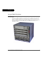
Avaya P460 Overview....................................................................................... 1
Introduction ........................................................................................................ 1
Avaya P460 Key Features: ................................................................................ 2
High Availability .................................................................................... 2
Flexibility ................................................................................................. 2
Management and Monitoring ............................................................... 2
Chapter 3
Avaya P460 Chassis and Module Installation ............................................... 3
Introduction ........................................................................................................ 3
Operating Safety ................................................................................................ 3
Required Tools ................................................................................................... 4
Environmental Prerequisites ............................................................................ 4
Chassis Component Location........................................................................... 6
Installing the P460 on a Table Top .................................................................. 7
Rack Mounting ................................................................................................... 7
P460 Rack mounting procedure: .......................................................... 9
Cable Guide Installation ................................................................................. 10
PSU (Power Supply Unit) Installation .......................................................... 11
Fan Module Replacement or Installation ..................................................... 12
Supervisor Module Installation ..................................................................... 14
I/O Module Installation.................................................................................. 16
I/O Module Installation Procedure ................................................... 17
Chapter 4
Turning on the Avaya P460............................................................................ 19
Avaya P460 Installation and Maintenance Guide
i
Table of Contents
Introduction ...................................................................................................... 19
Installing a PSU ................................................................................................ 19
Powering Up ..................................................................................................... 20
Turning on a Chassis with Supervisor and I/O Modules
Already Inserted ...................................................................................20
Turning on a Chassis with a Supervisor Module Only ...................20
Turning on a Chassis with no Modules .............................................20
Inserting an Additional PSU........................................................................... 20
Removing or Switching off a PSU.................................................................. 21
If there is one PSU .................................................................................21
If there are two PSUs ............................................................................21
If there are three PSUs ..........................................................................22
Power Management ......................................................................................... 23
The Power Management Process ........................................................23
ii
Chapter 5
Avaya P460 Panels ........................................................................................... 25
Introduction ...................................................................................................... 25
M460ML-SPV Panel ......................................................................................... 25
M460ML-SPV LEDs ..............................................................................25
ACT LED and OPR LED Summary ....................................................27
Function LEDs .................................................................................................. 28
M460ML-SPV Supervisor Module Ports....................................................... 31
Eth Port (Outband Connection) ..........................................................31
RS-232 Port (Sideband Connection) ...................................................31
M460ML-SPV Left and Right Pushbuttons .................................................. 31
M460ML-SPV ASB (Alternate Software Bank) Pushbutton....................... 32
Power Supply Panel......................................................................................... 33
Chapter 6
Maximizing Avaya P460 Availability ........................................................... 35
Introduction ...................................................................................................... 35
M460ML-SPV Supervisor Module Redundancy ......................................... 35
M460ML-SPV Supervisor Module Modes: .......................................35
Configuring the Supervisor Modules for Active/Standby
Operation ...............................................................................................36
Synchronizing the Supervisor Modules Manually ..........................36
Configuration File Synchronization ...................................................37
Redundant Power Supplies ............................................................................ 39
Calculating the Power Budget ............................................................40
Chapter 7
Establishing Switch Access ............................................................................. 41
Introduction ...................................................................................................... 41
Establishing a Console Connection with the P460 ...................................... 41
Establishing a Telnet Connection with the Switch (Inband)...................... 42
Inband Interface Connection CLI Commands ..................................42
Establishing a Telnet Connection with the Switch (Outband) .................. 43
Avaya P460 Installation and Maintenance Guide
Table of Contents
Outband Interface Connection CLI Commands .............................. 44
Redundant Outband Connections ..................................................... 45
Establishing a PPP via Modem Connection with the P460 (Sideband) ... 46
Overview ................................................................................................ 46
Sideband (PPP) Interface CLI Commands ........................................ 46
Setting Up Sideband (PPP) Connection Configuration .................. 47
Chapter 8
Avaya MSNM P460 Manager.........................................................................
PC System Requirements for Running the Avaya MSNM P460
Manager.............................................................................................................
Running the Avaya MSNM P460 Manager..................................................
Installing the Java Plug-in...............................................................................
Installing the On-Line Help and Java Plug-In on your Web Site..............
Documentation .................................................................................................
49
49
50
52
53
53
Chapter 9
User Authentication......................................................................................... 55
Introduction ...................................................................................................... 55
Local User Accounts ........................................................................................ 55
Access Levels ......................................................................................... 55
Local User Account CLI Commands ................................................. 56
RADIUS ............................................................................................................. 57
Introduction to RADIUS ...................................................................... 57
RADIUS CLI Commands .................................................................... 58
Allowed Managers........................................................................................... 60
Allowed Manager CLI Commands .................................................... 60
Chapter 10
Configuration Defaults ................................................................................... 61
Introduction ...................................................................................................... 61
Default System Parameters ............................................................................ 61
Configuration Default CLI Commands ............................................. 62
Chapter 11
Basic Switch Configuration ............................................................................ 63
Introduction ...................................................................................................... 63
System Parameter Configuration ....................................................... 64
Identifying the system ......................................................................... 64
Operating parameters .......................................................................... 64
Time Parameter Configuration ...................................................................... 65
Feature License Configuration....................................................................... 65
Feature Activation ................................................................................ 65
Obtaining a License Key ...................................................................... 66
Activating a Routing License Key ...................................................... 68
Feature License CLI Commands ........................................................ 68
Chapter 12
Troubleshooting the Installation.................................................................... 69
Introduction ...................................................................................................... 69
Avaya P460 Installation and Maintenance Guide
iii
Table of Contents
Powering up the Chassis ......................................................................69
Powering up the Supervisor Modules ...............................................69
Powering up the Fan Module .............................................................69
Powering up the I/O Modules ...........................................................70
Supervisor Module does not Boot ......................................................71
iv
Chapter 13
Maintenance ...................................................................................................... 73
Introduction ...................................................................................................... 73
Replacing I/O Modules................................................................................... 73
Replacing Supervisor Modules ...................................................................... 73
One Supervisor Module in the Switch ...............................................73
Two Supervisor Modules in the Switch .............................................73
Configuring the Supervisor Modules for Active/Standby
Operation ....................................................................................73
Firmware Download........................................................................................ 74
Introduction ...........................................................................................74
Preferred Bank .......................................................................................74
Booting from the Alternate Firmware Bank ..........................74
Firmware Download CLI Commands ...............................................75
Configuration File Management .................................................................... 75
Configuration Management CLI Commands ...................................75
Chapter 14
Standards........................................................................................................... 77
Introduction ...................................................................................................... 77
IEEE .........................................................................................................77
IETF .........................................................................................................77
Layer 2 .........................................................................................77
Layer 3 .........................................................................................78
Routing ...................................................................................................78
Chapter 15
Specifications .................................................................................................... 79
Physical .............................................................................................................. 79
Power Requirements........................................................................................ 80
MPS4603-AC Power Supply ....................................................80
Components ...............................................................................80
Environmental .................................................................................................. 80
Safety .................................................................................................................. 80
EMC Emissions................................................................................................. 81
Immunity ................................................................................................81
Transportation .......................................................................................81
Catalog Numbers ............................................................................................. 82
Avaya P460 Installation and Maintenance Guide
List of Tables
Table 3.1
Table 3.2
Table 3.3
Table 5.1
Table 5.3
Table 5.2
Table 5.5
Table 5.4
Table 5.6
Table 5.7
Table 5.8
Table 6.1
Table 6.2
Table 9.1
Table 10.1
Table 15.1
Environmental Requirements..................................................... 4
AC Power Requirements............................................................. 5
Dimensions.................................................................................... 5
Active M460ML-SPV LEDs....................................................... 25
Standby/Halted M460ML-SPV LEDs ..................................... 26
Active M460ML-SPV FastETH LED ........................................ 26
ACT and OPR LED Summary .................................................. 27
Standby M460ML-SPV FastETH LED ..................................... 27
M460ML-SPV Function LEDs................................................... 29
M460ML-SPV Left and Right Pushbutton Functions............ 31
Power Supply Status LED......................................................... 33
ACT and OPR LED Summary .................................................. 35
Sample Power Budget Calculation .......................................... 40
Access Level Descriptions......................................................... 55
Default System Parameters....................................................... 61
Avaya P460 Catalog Numbers ................................................. 82
Avaya P460 Installation and Maintenance Guide
v
List of Tables
vi
Avaya P460 Installation and Maintenance Guide
List of Figures
Figure 3.1
Figure 3.2
Figure 3.3
Figure 3.4
Figure 3.5
Figure 3.6
Figure 3.7
Figure 3.8
Figure 3.9
Figure 3.10
Figure 3.11
Figure 3.12
Figure 4.1
Figure 4.2
Figure 4.3
Figure 5.1
Figure 5.2
Figure 5.3
Figure 5.4
Figure 5.5
Figure 5.6
Figure 7.1
Figure 7.2
Figure 7.3
Figure 8.1
Figure 8.2
Figure 9.1
The Avaya P460 Switch – Component Location ..................... 6
Table-Top Installation.................................................................. 7
P460 Front-Mount and Mid-Mount Positions (side view) ..... 8
Positioning the rack-mounting brackets ................................... 9
Installing the Cable Guide ........................................................ 10
The Avaya P460 Switch – Fan Module Location ................... 12
Installing the Avaya P460 Fan Module ................................... 13
Location of the Avaya P460 Supervisor Modules ................. 14
Installing the P460 Supervisor Module................................... 15
Lcoation of Avaya P460 I/O Modules .................................... 16
I/O Module Component Location........................................... 17
Installing P460 I/O Modules .................................................... 18
Power Allocation after PSU Removal ..................................... 21
Power Management Priority .................................................... 23
I/O Module Power Management Process.............................. 24
M460ML-SPV LEDs ................................................................... 25
M460ML-SPV Function LEDs................................................... 28
Function LEDs Cycle ................................................................. 28
M460ML-SPV Supervisor Module Console Ports ................. 31
P460 Supervisor Module Left and Right Pushbutton ........... 31
P460 Supervisor Module ASB Pushbutton............................. 32
M460ML-SPV Supervisor Module Serial Console Port ........ 41
M460ML-SPV Supervisor Module Fast Ethernet Console
Port ............................................................................................... 43
Redundant Outband Connections ........................................... 45
The Welcome Page ..................................................................... 50
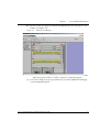
P460 Device Manager ................................................................ 51
RADIUS Authentication Procedure ........................................ 58
Avaya P460 Installation and Maintenance Guide
vii
List of Figures
viii
Avaya P460 Installation and Maintenance Guide
Preface
Before you Install the Avaya™ P460
Safety Information
Caution: The Avaya P460 switch and modules contain components sensitive to
electrostatic discharge. Do not touch the circuit boards unless instructed to do so.
Caution: Do not leave any slots open. Use the the blanking plates supplied to cover
empty slots.
Caution: Do not insert any objects into the P460 chassis other than specifically
designed Avaya products.
Warning: The fans are on whenever the power is on in the chassis, whether
supervisor modules are installed or not.
Warning: Keep your fingers and other objects clear of the fans when removing the
Fan module. The fans continue to turn briefly after you have removed the module.
Power Supplies
Caution: Risk of electric shock. Disconnection of one power supply cord disconnects
one power supply module only. To isolate unit completely from the mains
disconnect all power supply cords.
Avaya P460 Installation and Maintenance Guide
I
Preface
Caution: Gafahr des elektrischen Schocks. Entfernen des Netzsteckers eines
Netzteils legt nur dieses Netzteil spannungsfrei. Um alle Einheiten spannungsfrei
zu machen. Sind die Netzstecker aller Netxteile zu entfernen
Caution: Risque d'électrocution. Le débranchement d'un câble d'alimentation ne
déconnecte qu'un seul module d'alimentation. Pour isoler complètement l'unité du
secteur, débranchez tous les câbles d'alimentation.
FCC Notice
This equipment has been tested and found to comply with the limits for a Class A
digital device, pursuant to part 15 of the FCC Rules. These limits are designed to
provide reasonable protection against harmful interference when the equipment is
operated in a commercial environment. This equipment generates, uses, and can
radiate radio frequency energy and, if not installed and used in accordance with the
instruction manual, may cause harmful interference to radio communications.
Operation of this equipment in a residential area is likely to cause harmful
interference in which case the user will be required to correct the interference at his
own expense.
Changes or modifications to this equipment not expressly approved by Avaya Inc.
could void the user’s authority to operate the equipment.
Conventions Used in the Documentation
Documentation for this product uses the following conventions to convey
instructions and information:
Notes, Cautions and Warnings
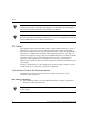
L Text with the L symbol contains helpful information or hints or reference to
material in other documentation.
Caution: Take care. You could do something that may damage equipment or result
in loss of data.
II
Avaya P460 Installation and Maintenance Guide
Preface
Warning: This means danger. Failure to follow the instructions or warnings might
result in bodily injury. Ensure that you are qualified for this task and have read and
understood all the instructions
CLI Conventions
•
•
•
•
•
•
•
Mandatory keywords are in the computer bold font.
Information displayed on screen is displayed in computer font.
Variables that you supply are in pointed brackets <>.
Optional keywords are in square brackets [].
Alternative but mandatory keywords are grouped in braces {} and separated by
a vertical bar |.
Lists of parameters from which you can choose are enclosed in square brackets
[ ] and separated by a vertical bar |.
If you enter an alphanumeric string of two words or more, enclose the string in
inverted commas””.
Warranty
Avaya Inc. provides a limited warranty on this product. Refer to your sales
agreement or other applicable documentation to establish the terms of the limited
warranty. In addition, Avaya’s standard warranty language as well as information
regarding support for this product, while under warranty, is available through the
following website: http://www.support.avaya.com.
Notice
Every effort was made to ensure that the information in this document was
complete and accurate at the time of printing. However, information is subject to
change.
Avaya Support
Avaya provides a telephone number for you to use to report problems or to ask
questions about your contact center. The support telephone number is 1-800-2422121 in the United States. For additional support telephone numbers, see the Avaya
Web site: http://www.avaya.com
Select Support, then select Escalation Lists. This Web site includes telephone
numbers for escalation within the United States. For escalation telephone numbers
outside the United States, select Global Escalation List.
Avaya P460 Installation and Maintenance Guide
III
Preface
IV
Avaya P460 Installation and Maintenance Guide
Chapter 2
Avaya P460 Overview
Introduction
The Avaya™ P460 is a flexible six-slot modular chassis, with two slots reserved for
supervisor modules and the four remaining slots for switched I/O modules. It is
ideal as a LAN edge and wiring closet switch for SMEs or as an “all-in-one” solution
for branch offices. You can also deploy the Avaya P460 in data centers or as a
distribution switch.
Avaya P460 Installation and Maintenance Guide
1
Chapter 2
Avaya P460 Overview
Avaya P460 Key Features:
High Availability
• Redundant Supervisor modules
• Redundant switching fabric
• Three power supply bays that support redundant (optional), load-sharing and
fault-tolerant AC power supplies.
• Hot-swappable fan module
• Hot-swappable supervisor modules
• Hot-swappable I/O modules
• Meets requirements for device redundancy, link resiliency and network
availability.
• Access to all components from the front of the chassis.
Flexibility
•
•
•
Broad range of I/O modules, including
— 48 10/100 ports
— 48 10/100 ports + 2 Gigabit Ethernet ports
— 12 Gigabit Ethernet ports.
Modular chassis flexibility with a variety of module/speed mixes.
Upgradeable to Layer 3 switching with an optional license
Management and Monitoring
• Built-in Web-based device manager
• Avaya™ Multiservice Network Manager suite (optional)
• Standards-based SMON Switch Monitoring (optional, requires license)
2
Avaya P460 Installation and Maintenance Guide
Chapter 3
Avaya P460 Chassis and Module Installation
Introduction
This chapter guides you through the basic hardware Installation process.
L If you purchased an Avaya P460ML-CFG (Material code 700255003, PEC Code
4548-009), then one Supervisor Module, PSU and the Fan Module are already
installed.
Operating Safety
Caution: The Avaya P460 switch and modules contain components sensitive to
electrostatic discharge. Do not touch the circuit boards unless instructed to do so.
Use appropriate anti-static equipment when handling the switch and modules.
Caution: Do not leave any slots open. Use the the blanking plates supplied to cover
empty slots.
Caution: Do not insert any objects into the P460 chassis other than specifically
designed Avaya products.
Warning: Keep your fingers and other objects clear of the fans when removing the
Fan module. The fans continue to turn briefly after you have removed the module.
Danger: Keep your fingers and other objects clear of the fans when removing the
tray as the fans continue to turn briefly after you have removed it.
Avaya P460 Installation and Maintenance Guide
3
Chapter 3
Avaya P460 Chassis and Module Installation
Required Tools
You require the following equipment in order to install the P460 chassis:
• Phillips (cross-blade) screwdriver
Environmental Prerequisites
Danger: To avoid injury, Avaya recommends that two people lift the switch onto a
table top. A fully loaded P460 switch weighs at least 100 lbs (45 kg).
You can position the Avaya P460 in free-standing mode on a suitable shelf or table,
or mount it in a standard 19-inch equipment rack in a wiring closet or equipment
room.
When deciding where to position the chassis, ensure that:
• It is accessible and cables can be connected easily and according to the
configuration rule.
• Cables are away from sources of electrical noise such as:
— radio transmitters
— broadcast amplifiers
— power lines
— fluorescent lighting fixtures.
• Water or moisture cannot enter the case of the chassis.
• There is a free flow of air around all sides the chassis.
• The vents on the sides of the case are not blocked.
• The table or shelf can hold the weight of the chassis with the PSUs and modules.
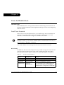
• The environmental conditions match the requirements listed in Table 3.1.
L See Chapter 15, “Specifications“ for additional information.
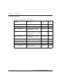
Table 3.1
4
Environmental Requirements
Ambient temperature
23o to 122oF (-5o to 50oC)
Relative humidity
5% to 95%, non condensing
Minimum clearance for
ventilation
2" (5 cm) on each side
Weight support
50 lb. (23 kg) to 100 lbs (45 kg)
Avaya P460 Installation and Maintenance Guide
Chapter 3
•
Avaya P460 Chassis and Module Installation
The power source matches the specifications shown in Table 3.2.
Table 3.2
AC Power Requirements
Voltage
100 to 240 VAC, 50/60 Hz
Current for one Avaya
MPS4603-AC
300 W PSU
3.9 A@100 VAC
1.5 A@200VAC
Table 3.3
Dimensions
Height
10U (17.5", 444.5 mm)
Width
17.4" (442 mm)
Depth
15" (375 mm)
Avaya P460 Installation and Maintenance Guide
5
Chapter 3
Avaya P460 Chassis and Module Installation
Chassis Component Location
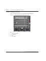
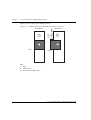
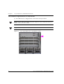
Figure 3.1 shows the positions of the components in the P460 chassis.
Figure 3.1
The Avaya P460 Switch – Component Location
1
2
4
3
Key
1
2
3
4
6
Supervisor modules
I/O Modules
PSUs
Fan module
Avaya P460 Installation and Maintenance Guide
Chapter 3
Avaya P460 Chassis and Module Installation
Installing the P460 on a Table Top
Place the system on a surface that supports at least 100 lbs (45 kg).
5 Install the supplied rubber feet to the bottom of the switch, placing the feet in
the square recesses provided. See Figure 3.2.
Clean the surface of any oils or residue before applying the feet.
Figure 3.2
Table-Top Installation
Rubber feet
6
Ensure that all the preinstalled components are firmly installed in the chassis.
These include:
— Supervisor modules
— Power supply
— Fan module
Caution: Do not place other equipment on top of the P460.
Rack Mounting
Danger: To avoid injury, Avaya recommends that two people to lift the switch onto
a table top. A fully loaded P460 switch weighs at least 100 lbs (45 kg).
You can mount the Avaya P460 in a standard 19" rack either in “front-mount” or
“mid-mount” positions with the brackets supplied with the chassis.
The brackets are symmetric: you can fix either bracket one either side.
Avaya P460 Installation and Maintenance Guide
7
Chapter 3
Avaya P460 Chassis and Module Installation
Figure 3.3 shows the two mounting positions:
P460 Front-Mount and Mid-Mount Positions (side view)
Front-Mount
a
5.5”
(140 mm)
Figure 3.3
a
b
b
Front
Mid-Mount
Front
Key
a Rack
b P460 switch
L The chassis height is 10U.
8
Avaya P460 Installation and Maintenance Guide
Chapter 3
Avaya P460 Chassis and Module Installation
P460 Rack mounting procedure:
1 Position the brackets as shown in Figure 3.4
Figure 3.4
Positioning the rack-mounting brackets
b
a
P4
60
3
3
b
a
Key
a
b
Front-mount position
Mid-mount position
2
Firmly fix the brackets to the chassis with the screws provided. Use five screws
for each bracket.
3 Position the switch in the rack.
4 Fasten the switch in the rack with the screws provided.
L The screw size is 8-32x¼
Caution: Do not place other equipment on top of the P460
Avaya P460 Installation and Maintenance Guide
9
Chapter 3
Avaya P460 Chassis and Module Installation
Cable Guide Installation
You can use the cable guide to tidy cables from the Supervisor and I/O modules.
The cable guide is symmetric: you can install the bracket on either side of the switch.
L Avaya recommends that you install the cable guide on the left side of the switch
to allow easier access to the fan module.
L You need to install the rack mounting brackets before you can install the cable
guides.
L Install the switch in the rack before installing the cable guide.
• Secure the cable guide to the rack mounting bracket using the captive screws on
the cable holder (see Figure 3.5).
Figure 3.5
Installing the Cable Guide
Left side of chassis
a
Right side of chassis
b
a
b
Key
a
b
10
Cable Guide
Rack-mounting bracket
Avaya P460 Installation and Maintenance Guide
Chapter 3
Avaya P460 Chassis and Module Installation
PSU (Power Supply Unit) Installation
L If you purchased an Avaya P460ML-CFG (Material code 700255003, PEC Code
4548-009), then one Supervisor Module, PSU and the Fan Module are already
installed.
For further information on Power Supply Installation, see Chapter 4, “Turning on
the Avaya P460“
Avaya P460 Installation and Maintenance Guide
11
Chapter 3
Avaya P460 Chassis and Module Installation
Fan Module Replacement or Installation
L The P460 Chassis is shipped with a fan module already installed.
Danger: Ensure that your fingers and other objects are clear of the fans when you
insert or remove the fan module.
Danger: The fans rotate whenever the chassis is turned on.
Figure 3.6
12
The Avaya P460 Switch – Fan Module Location
Avaya P460 Installation and Maintenance Guide
Chapter 3
Figure 3.7
Avaya P460 Chassis and Module Installation
Installing the Avaya P460 Fan Module
P4
60
aaaaaaa
aaaaaaa
aaaaaaa
aaaaaaa
aaaaaaa
aaaaaaa
aaaaaaa
aaaaaaa
aaaaaaa
aaaaaaa
aaaaaaa
aaaaaaa
aaaaaaa
aaaaaaaaaaa
aaaaaaaaaa
aaaaaaa
aaaaaaa
aaaaaaa
aaaaaaa
aaaaaaa
aaaaaaa
aaaaaaa
aaaaaaa
aaaaaaa
aaaaaaa
aaaaaaa
aaaaaaa
aaaaaaa
a a a a
aaaaaaaaaa
aaaaaaa
aaaaaaa
aaaaaaa
aaaaaaa
aaaaaaa
aaaaaaa
aaaaaaa
aaaaaaa
aaaaaaa
aaaaaaa
aaaaaaa
aaaaaaa
aaaaaaa
aaaaaaa
aaaaaaa
aaaaaaa
aaaaaaa
a aaaaa
aaaaaaaaa
aaaaaaaa
aaaaaaaa
aaaaaaaa
aaaaaaaa
aaaaaaaa
aaaaaaaa
aaaaaaaa
aaaaaaaa
aaaaaaaa
aaaaaaaa
aaaaaaaa
aaaaaaaa
aaaaaaaaaaaa
aaaaaaaaaaaa
aaaaaaaa
aaaaaaaa
aaaaaaaa
aaaaaaaa
aaaaaaaa
aaaaaaaa
aaaaaaaa
aaaaaaaa
aaaaaaaa
a aaaaaa
aaaaaaaa
aaaaaaaa
a a a a
aaaaaaaaaaaa
a a a a
aaaaaaaa
aaaaaaaa
aaaaaaaa
aaaaaaaa
aaaaaaaa
aaaaaaaa
aaaaaaaa
aaaaaaaa
aaaaaaaa
aaaaaaaa
aaaaaaaa
aaaaaaaa
aaaaaaaa
aaaaaaaa
aaaaaaaa
aaaaaaaa
aaaaaaaa
a a a a
aaaaaaaa
aaaaaaaa
aaaaaaaa
aaaaaaaa
aaaaaaaa
aaaaaaaa
aaaaaaaa
aaaaaaaa
aaaaaaaa
aaaaaaaa
aaaaaaaa
aaaaaaaa
aaaaaaaa
aaaaaaaaaaaa
aaaaaaaaaaaa
aaaaaaaa
aaaaaaaa
aaaaaaaa
aaaaaaaa
aaaaaaaa
aaaaaaaa
aaaaaaaa
aaaaaaaa
aaaaaaaa
aaaaaaaa
aaaaaaaa
aaaaaaaa
a a a a
aaaaaaaaaaaa
aaaaaaaa
aaaaaaaa
aaaaaaaa
aaaaaaaa
aaaaaaaa
aaaaaaaa
a a a a
aaaaaaaa
aaaaaaaa
aaaaaaaa
aaaaaaaa
aaaaaaaa
aaaaaaaa
aaaaaaaa
aaaaaaaa
aaaaaaaa
aaaaaaaa
aaaaaaaa
aaaaaaaa
aaaaa
aaaa
aaaa
aaaa
aaaa
aaaa
aaaa
aaaa
aaaa
aaaa
aaaa
a aa
aaaaa
aaaa
aaaa
aaaa
aaaa
aaaa
aaaa
aaaa
aaaa
aaaa
aaaa
aaaa
aaaa
aaaa
aaaa
a a
aaaaaa
aaaa
aaaa
aaaa
aaaa
aaaa
a aa
aaaa
aaaa
aaaa
aaaa
aaaa
aaaa
aaaa
aaaa
aaaa
aaaa
a a
M48
0-FA
N
Caution: You need to replace the fan module within five minutes. If you do not, the
I/O modules are shut down automatically to prevent overheating of the modules.
If this occurs, turn off the chassis and turn it on again.
To install a fan module:
1 Remove the existing fan module.
a Loosen the fastening screws.
b Gently pull the module towards you.
2 Position the module in the slot with the screws to the right side of the chassis
(see Figure 3.7).
3 Gently slide the module in.
4 Gently tighten the screws.
Avaya P460 Installation and Maintenance Guide
13
Chapter 3
Avaya P460 Chassis and Module Installation
Supervisor Module Installation
L If you purchased an Avaya P460ML-CFG (Material code 700255003, PEC Code
4548-009), then one Supervisor Module, PSU and the Fan Module are already
installed.
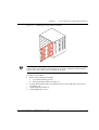
Figure 3.8 shows the positions of the SPV Supervisor installed in the P460 chassis.
Figure 3.8
Location of the Avaya P460 Supervisor Modules
L You can install Supervisor modules in the top two slots – 1 and 2 – only.
Caution: Do not leave any slots open. Use the the blanking plates supplied to cover
empty slots.
Caution: The Supervisor modules contain components that are sensitive to static
discharge. Handle the module by the edges only.
Use appropriate anti-static equipment when handling the modules.
14
Avaya P460 Installation and Maintenance Guide
Chapter 3
Figure 3.9
Avaya P460 Chassis and Module Installation
Installing the P460 Supervisor Module
P4
60
a
3
3
b
aaaaaaa
aaaaaaa
aaaaaaa
aaaaaaa
aaaaaaa
aaaaaaa
aaaaaaa
aaaaaaa
aaaaaaa
aaaaaaa
aaaaaaa
aaaaaaa
aaaaaaa
aaaaaaaaaaa
aaaaaaaaaa
aaaaaaa
aaaaaaa
aaaaaaa
aaaaaaa
aaaaaaa
aaaaaaa
aaaaaaa
aaaaaaa
aaaaaaa
aaaaaaa
aaaaaaa
aaaaaaa
aaaaaaa
a a a a
aaaaaaaaaa
aaaaaaa
aaaaaaa
aaaaaaa
aaaaaaa
aaaaaaa
aaaaaaa
aaaaaaa
aaaaaaa
aaaaaaa
aaaaaaa
aaa a a
aaaaaaa
aaaaaaa
aaaaaaa
aaaaaaa
aaaaaaa
aaaaaaa
a a a a
aaaaaaaaaaaa
aaaaaaaa
aaaaaaaa
aaaaaaaa
aaaaaaaa
aaaaaaaa
aaaaaaaa
aaaaaaaa
aaaaaaaa
aaaaaaaa
aaaaaaaa
aaaaaaaa
aaaaaaaa
aaaaaaaaaaaa
aaaaaaaaaaaa
aaaaaaaa
aaaaaaaa
aaaaaaaa
aaaaaaaa
aaaaaaaa
aaaaaaaa
aaaaaaaa
aaaaaaaa
aaaaaaaa
aaaaaaaa
aaaaaaaa
aaaaaaaa
a a a a
aaaaaaaaaaaa
aaaaaaaa
aaaaaaaa
aaaaaaaa
aaaaaaaa
aaaaaaaa
aaaaaaaa
aaaaaaaa
aaaaaaaa
aaaaaaaa
aaaaaaaa
aaaaaaaa
aaaaaaaa
aaaaaaaa
aaaaaaaa
aaaaaaaa
aaaaaaaa
aaaaaaaa
aaaaaaaa
a a a a
aaaaaaaaaaaa
aaaaaaaa
aaaaaaaa
aaaaaaaa
aaaaaaaa
aaaaaaaa
aaaaaaaa
aaaaaaaa
aaaaaaaa
aaaaaaaa
aaaaaaaa
aaaaaaaa
aaaaaaaa
aaaaaaaaaaaa
aaaaaaaaaaaa
aaaaaaaa
aaaaaaaa
aaaaaaaa
aaaaaaaa
aaaaaaaa
aaaaaaaa
aaaaaaaa
aaaaaaaa
aaaaaaaa
aaaaaaaa
aaaaaaaa
aaaaaaaa
a a a a
aaaaaaaaaaaa
aaaaaaaa
aaaaaaaa
aaaaaaaa
aaaaaaaa
aaaaaaaa
aaaaaaaa
aaaaaaaa
aaaaaaaa
aaaaaaaa
aaaaaaaa
aaaaaaaa
aaaaaaaa
aaaaaaaa
aaaaaaaa
aaaaaaaa
aaaaaaaa
aaaaaaaa
aaaaaaaa
a a a a
aaaaaa
aaaa
aaaa
aaaa
aaaa
aaaa
aaaa
aaaa
aaaa
aaaa
aaaa
a a
aaaaaa
aaaa
aaaa
aaaa
aaaa
aaaa
aaaa
aaaa
aaaa
aaaa
aaaa
aaaa
aaaa
aaaa
aaaa
a a
aaaaaa
aaaa
aaaa
aaaa
aaaa
aaaa
aaaa
aaaa
aaaa
aaaa
aaaa
aaaa
aaaa
aaaa
aaaa
aaaa
aaaa
a a
Key
a
b
Open locking handle
Closed locking handle
To install a Supervisor module:
1 Remove the blanking plate or installed module as appropriate.
2 Open the locking handles at the edge of the front panel.
3 Position the module in the slot as shown in Figure 3.9.
4 Gently slide the module in.
L Ensure the hooks on the locking handle are aligned with the matching holes on
the chassis.
5 Close the locking handles.
X The module slides back and connects to the backplane.
6 Gently tighten the screws.
L For information on configuring redundant supervisor modules, refer to
“M460ML-SPV Supervisor Module Redundancy“ on page 35.
Avaya P460 Installation and Maintenance Guide
15
Chapter 3
Avaya P460 Chassis and Module Installation
I/O Module Installation
L If you purchased an Avaya P460ML-CFG (Material code 700255003, PEC Code
4548-009), then one Supervisor Module, PSU and the Fan Module are already
installed.
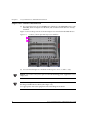
Figure 3.10 shows the positions of I/O modules installed in the P460 chassis.
Figure 3.10
Lcoation of Avaya P460 I/O Modules
L You can install I/O modules in the bottom four slots – 3 to 6 – only.
Caution: Do not leave any slots open. Use the the blanking plates supplied to cover
empty slots.
Caution: The I/O modules contain components that are sensitive to static discharge.
Handle the module by the edges only.
Use appropriate anti-static equipment when handling the switch and modules.
16
Avaya P460 Installation and Maintenance Guide
Chapter 3
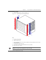
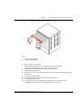
Figure 3.11
Avaya P460 Chassis and Module Installation
I/O Module Component Location
1
2
3
2
3
Key
1
2
3
Module label
Securing screws
Locking handles
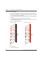
I/O Module Installation Procedure
To install an I/O module:
1 Remove the blanking plate by unscrewing the captive screws and gently pulling
the plate towards you.
2 Open the locking handles at the edge of the front panel. See Figure 3.12.
3 Position the module as shown in Figure 3.12.
4 Gently slide the module in.
L Ensure the hooks on the locking handle are aligned with the matching holes on
the chassis.
5 Close the locking handles.
X The module slides back and connects to the backplane.
6 Gently tighten the screws.
L For module-specific information, refer to the Installation Guide shipped with
the module.
Avaya P460 Installation and Maintenance Guide
17
Chapter 3
Avaya P460 Chassis and Module Installation
Figure 3.12
Installing P460 I/O Modules
P4
60
3
3
a
b
aaaaaaa
aaaaaaa
aaaaaaa
aaaaaaa
aaaaaaa
aaaaaaa
aaaaaaa
aaaaaaa
aaaaaaa
aaaaaaa
aaaaaaa
a aaaaa
aaaaaaa
aaaaaaaaaaa
aaaaaaa
aaaaaaa
aaaaaaa
aaaaaaa
a a a a
aaaaaaa
aaaaaaa
aaaaaaa
aaaaaaa
a a a a
aaaaaaa
aaaaaaa
aaaaaaa
a a a a
a a a a
aaaaaaaaaa
aaaaaaa
a a a a
aaaaaaa
aaaaaaa
aaaaaaa
a a a a
aaaaaaa
aaaaaaa
aaaaaaa
aaaaaaa
aaaaaaa
aaaaaaa
aaaaaaa
aaaaaaa
aaaaaaa
aaaaaaa
aaaaaaa
aaaaaaa
aaaaaaaa
aaaaaaaa
aaaaaaaa
aaaaaaaa
aaaaaaaa
aaaaaaaa
aaaaaaaa
aaaaaaaa
aaaaaaaa
aaaaaaaa
aaaaaaaa
aaaaaaaa
aaaaaaaa
aaaaaaaaaaaa
aaaaaaaaaaaa
aaaaaaaa
aaaaaaaa
aaaaaaaa
aaaaaaaa
a aaaaaa
aaaaaaaa
a aaaaaa
aaaaaaaa
aaaaaaaa
aaaaaaaa
aaaaaaaa
a a a a
a a a a
aaaaaaaaaaaa
aaaaaaaa
aaaaaaaa
a a a a
aaaaaaaa
aaaaaaaa
aaaaaaaa
a a a a
aaaaaaaa
aaaaaaaa
aaaaaaaa
aaaaaaaa
a a a a
aaaaaaaa
aaaaaaaa
aaaaaaaa
aaaaaaaa
aaaaaaaa
aaaaaaaa
aaaaaaaa
aaaaaaaa
aaaaaaaa
aaaaaaaa
aaaaaaaa
aaaaaaaa
aaaaaaaa
aaaaaaaa
aaaaaaaa
aaaaaaaa
aaaaaaaa
aaaaaaaa
aaaaaaaa
aaaaaaaa
aaaaaaaaaaaa
aaaaaaaaaaaa
aaaaaaaa
aaaaaaaa
aaaaaaaa
aaaaaaaa
aaaaaaaa
aaaaaaaa
a aaaaaa
aaaaaaaa
aaaaaaaa
aaaaaaaa
aaaaaaaa
aaaaaaaa
a a a a
aaaaaaaaaaaa
aaaaaaaa
aaaaaaaa
aaaaaaaa
a a a a
aaaaaaaa
aaaaaaaa
aaaaaaaa
aaaaaaaa
a a a a
aaaaaaaa
aaaaaaaa
aaaaaaaa
aaaaaaaa
a a a a
aaaaaaaa
aaaaaaaa
aaaaaaaa
a a a a
aaaaaaaa
aaaa
aaaa
aaaa
aaaa
aaaa
aaaa
aaaa
aaaa
aaaa
aaaa
aaaa
aaaa
aaaa
aaaa
aaaa
aaaa
aaaa
aaaa
aaaa
aaaa
aaaa
aaaa
aaaa
aaaa
aaaa
aaaa
aaaa
a a
aaaaaa
a aa
aaaa
aaaa
aaaa
aaaa
a a
aaaa
aaaa
aaaa
aaaa
a a
aaaa
aaaa
aaaa
aaaa
a a
aaaa
Key
a
b
18
Open locking handle
Closed locking handle
Avaya P460 Installation and Maintenance Guide
Chapter 4
Turning on the Avaya P460
Introduction
Once you have installed the Avaya P460 chassis and modules, you can turn the
chassis on. The Avaya P460 chassis can accommodate one, two or three PSUs
(Power Supply Units). The available power is divided among the modules by the
Supervisor Module. See “Power Management“ on page 23 further information.
This chapter describes three basic scenarios:
• Turning on the P460 chassis in various configurations.
• Adding a PSU to the P460 chassis.
• Removing a PSU from the chassis.
Danger: The fans are on whenever the power is on in the chassis.
Caution: Do not leave any PSU slots open. Use the the blanking plates supplied to
cover empty slots.
Installing a PSU
L Use the handle on the front panel of the PSU to lift it.
L You can install the PSU in any of the three slots.
1 Remove the blanking plate by unscrewing the four retaining screws and gently
tugging the plate towards you.
2 Position the PSU with the label facing up and to the right.
3 Gently slide the PSU back until the socket on the back of the PSU engages in the
plug on the chassis.
L Ensure the guiding pins on the front panel of the PSU align with the holes on
the front panel of the P460 chassis.
4 Gently tighten the screws on the PSU.
Avaya P460 Installation and Maintenance Guide
19
Chapter 4
Turning on the Avaya P460
Powering Up
In order to turn on the chassis you need to install at least one PSU and at least one
Supervisor Module.
L The fans are on whenever the power is on in the chassis, whether Supervisor
Modules are installed or not.
Turning on a Chassis with Supervisor and I/O Modules Already Inserted
If you have inserted Supervisor module(s) and I/O module(s) into the chassis before
turning on the PSUs, the power-up procedure is as follows:
1 The Supervisor module(s) and fans are turned on automatically when the PSUs
are turned on.
2 The Supervisor module will turn on the modules one by one, verifying that
there is enough power budget in the system first. If there are two Supervisor
modules, the Active Supervisor Module perfoms this procedure.
Turning on a Chassis with a Supervisor Module Only
L The fans are on whenever the power is on in the chassis, whether Supervisor
Modules are installed or not.
If you turn on the PSU(s) in a chassis with a Supervisor Module, the power-up
procedure is as follows:
1 The fans start.
2 The supervisor module is turned on.
X You can now insert I/O Modules
Turning on a Chassis with no Modules
If you turn on the PSU(s) in an empty chassis – no Supervisor modules – the fans
will start up.
Inserting an Additional PSU
1
2
3
20
The SPV adds the new PSU power budget and checks how many PSUs are
present in the chassis
Modules not powered up because of an insufficient power budget are turned
on. Otherwise the new PSU power is just added to the total available power.
The PSU you insert are in redundant mode if the existing PSUs can already
provide enough power for the chassis and installed components.
Avaya P460 Installation and Maintenance Guide
Chapter 4
Turning on the Avaya P460
Removing or Switching off a PSU
If there is one PSU
The entire chassis turns off
If there are two PSUs
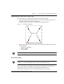
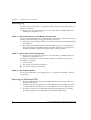
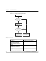
1 When you remove a PSU from the chassis, the Supervisor Module recalculates
the power budget. If the power requirement exceeds the capacity of one PSU,
the I/O modules are then turned on according to the power budgeting scheme
described below. See Figure 4.1.
a The chassis is automatically turned on with only the Supervisor Modules
and the fans getting power from the available PSU
b If all the available I/O modules were operational before the PSU removal/
failure, the Supervisor Module starts to apply power. The power is first
applied to as many I/O modules as possible within the power budget limit
of the single PSU. This can mean that an I/O module with a low power
requirement and low priority is powered up rather than a high power
requirement module with a higher priority.
c Slots whose power is disabled are skipped.
Figure 4.1
Power Allocation after PSU Removal
No
Power enabled
for slot 5?
Start power allocation
Yes
Power enabled
for slot 3?
No
Sufficient power
budget?
Yes
Yes
Sufficient power
budget?
Apply power to slot 5
No
Yes
No
Apply power to slot 3
Power enabled
for slot 6?
Yes
Power enabled
for slot 4?
Sufficient power
budget?
Yes
Yes
Sufficient power
budget?
Apply power to slot 6
Yes
Apply power to slot 4
Avaya P460 Installation and Maintenance Guide
21
Chapter 4
Turning on the Avaya P460
If there are three PSUs
The chassis continues to run: two PSUs are sufficient to supply power to a fully
populated chassis.
22
Avaya P460 Installation and Maintenance Guide
Chapter 4
Turning on the Avaya P460
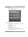
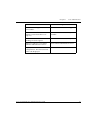
Power Management
The Supervisor module checks the PSU status every three seconds by comparing the
current state to the previously saved PSU state.
Figure 4.2
Power Management Priority
1
2
3
4
5
6
The Power Management Process
L The power management process is activated in the SPV only if there is a change
in power requirements or supply caused by one of the following events:
• Power-up sequence
• PSU removal if there are two PSUs
• PSU insertion if there is only one PSU
• I/O module insertion
• I/O module removal
• Administratively enabling/disabling a slot
L Removing both supervisors turns off the entire system.
L In case of power failure in a module, the Supervisor module receives an
indication from the failed module. The Supervisor module will turn off the I/O
module and issues a warning.
Avaya P460 Installation and Maintenance Guide
23
Chapter 4
Turning on the Avaya P460
•
You can also administratively enable/disable power supply to a specific I/O
module slot with the set slot power CLI command.
L The power allocation configuration is saved in NVRAM and treated as any
other switch configuration.
L If you want to view the power status of the P460 chassis and modules, you can
use the show environment power CLI command.
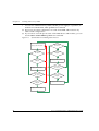
Figure 4.3
I/O Module Power Management Process
Power enabled
for slot 5?
Start power allocation
Yes
Power enabled
for slot 3?
Sufficient power
budget?
Yes
Yes
Sufficient power
budget?
Apply power to slot 5
No
Yes
Apply power to slot 3
Power enabled
for slot 6?
Yes
Power enabled
for slot 4?
Sufficient power
budget?
Yes
Yes
Sufficient power
budget?
Apply power to slot 6
Yes
Apply power to slot 4
24
Avaya P460 Installation and Maintenance Guide
Chapter 5
Avaya P460 Panels
Introduction
This chapter describes the front panels of the P460 switch modules, including the
LEDs, ports and buttons.
M460ML-SPV Panel
M460ML-SPV modules can operate in three modes: Active, Standby and Halted.
Each mode is reflected in the LEDs – further details are provided in Table 5.1.
M460ML-SPV LEDs
Figure 5.1
M460ML-SPV LEDs
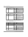
Table 5.1 summarizes the functions of the LEDs for an active M460ML-SPV
supervisor module.
Table 5.1
Active M460ML-SPV LEDs
LED
Description
State
ACT
Active SPV indication
ON
ROUT
Device switching mode
ON
Layer 3
OFF
Layer 2
ON
CPU boot and BIT (built-in
test) completed
Blinking
CPU booting or running BIT
Fan module not installed.
OFF
CPU cannot boot (see Chapter
12, "Troubleshooting the
Installation")
OPR
CPU operation
System status
Avaya P460 Installation and Maintenance Guide
Meaning
25
Chapter 5
Avaya P460 Panels
Table 5.1
Active M460ML-SPV LEDs
LED
Description
State
Meaning
PWR
Power information
ON
Power is up
Blinking
Power management error: the
switch cannot supply power to
at least one module
OFF
Power is off
Table 5.2
Active M460ML-SPV FastETH LED
LED
Description
State
Meaning
Fast
ETH
Management outband
Ethernet link status
ON
Port enabled and link OK
No data transmitted or
received on the port
Blinking
Port enabled and link OK
Data transmitted or received
on the port
OFF
Link is not operating
Table 5.3 summarizes the functions of the LEDs for a standby or halted
M460ML-SPV supervisor module.
Table 5.3
LED
Description
State
ACT
Active SPV indication
OFF
ROUT
Device switching mode
OFF
OPR
CPU operation
ON
CPU boot and BIT completed
Module in Standby mode
Blinking
Module in Halted mode or
CPU and BIT not completed
ON
Power is up
OFF
Power is off
PWR
26
Standby/Halted M460ML-SPV LEDs
Power information
Meaning
Avaya P460 Installation and Maintenance Guide
Chapter 5
Table 5.3
Standby/Halted M460ML-SPV LEDs
LED
Description
State
Fast
ETH
Management outband
Ethernet link status
OFF
Table 5.4
Avaya P460 Panels
Meaning
Standby M460ML-SPV FastETH LED
LED
Description
State
Meaning
Fast
ETH
Management outband
Ethernet link status
ON
Port enabled and link OK
No data transmitted or
received on the port
Blinking
Port enabled and link OK
Data transmitted or received
on the port
OFF
Link is not operating
ACT LED and OPR LED Summary
Table 5.5 summarizes the states of the ACT and OPR LEDs
Table 5.5
ACT and OPR LED Summary
ACT LED is...
OPR LED is...
M460ML-SPV Module is...
ON
ON
Active
ON
Blinking
Active
Fan Module not inserted
OFF
ON
Standby
OFF
Blinking
Halted or booting
Fan Module not inserted
Avaya P460 Installation and Maintenance Guide
27
Chapter 5
Avaya P460 Panels
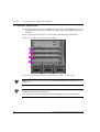
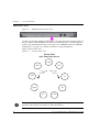
Function LEDs
Figure 5.2
M460ML-SPV Function LEDs
Use the L (Left) and R (Right) pushbuttons to select the information displayed for all
the port LEDs on the installed I/O modules. Press the button to cycle through the
options: the illuminated LED shows the option. See “M460ML-SPV Left and Right
Pushbuttons“ on page 31 for further information on the pushbuttons.
Figure 5.3 shows the cycle.
Figure 5.3
Function LEDs Cycle
Starting Point
(after Power-up or Reset)
LNK
COL
PoE
Left
Button
Right
Button
LAG
Tx
Hspd
Rx
FC
FDX
Note: The LEDs indicate which information is displayed on the port LEDs on I/O
modules: check each I/O module to see the information.
28
Avaya P460 Installation and Maintenance Guide
Chapter 5
Avaya P460 Panels
Note: Press both buttons simultaneously for 1.5 seconds to reset the SPV supervisor
module.
Press both switches simultaneously for five seconds to reset the entire switch. Refer
to "M460ML-SPV Left and Right Pushbuttons" on page 31 for full details of reset
options.
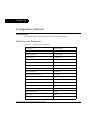
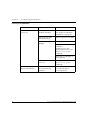
Table 5.6 summarizes the meanings of the function LEDs. Certain indications
depend on the specific I/O module port type:
Table 5.6
M460ML-SPV Function LEDs
LED
Description
State
Meaning
LNK
Port status
ON
Port enabled and link OK
OFF
Port disabled or link is not
operating
ON
Collision occurred on line
OFF
No collision or FDX port
ON
Data transmitted to the line
OFF
No transmit activity
ON
Data received from the line
OFF
No receive activity
ON
Full-duplex mode
For 10/100BASE-T ports when
the link test fails with autonegotiation enabled
OFF
Half-duplex mode
ON
Flow Control is active
OFF
Flow Control is disabled
ON
Port
10/100
1000
100 Mbps 1000 Mbps
OFF
Port
10/100
1000
10 Mbps N/A
COL
Tx
Rx
FDX
FC
HSpd
Collision detection
Transmit to line
Receive from line
Full-/Half-duplex
Indication
Flow Control
Port speed indication
Avaya P460 Installation and Maintenance Guide
29
Chapter 5
Avaya P460 Panels
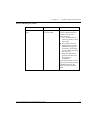
Table 5.6
M460ML-SPV Function LEDs
LED
Description
State
Meaning
LAG
Link Aggregation
Group
ON
Port is a member of a LAG
OFF
Port is not a member of a LAG
Power over Ethernet
ON
PoE is enabled and power is
being supplied to an endstation
Blinking
• PoE enabled, but no
powered device is detected,
or
• Power supply error, or
• Not enough power
OFF
PoE disabled for this port
PoE*
*Not currently implemented
30
Avaya P460 Installation and Maintenance Guide
Chapter 5
Avaya P460 Panels
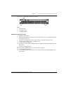
M460ML-SPV Supervisor Module Ports
Figure 5.4
M460ML-SPV Supervisor Module Console Ports
1
2
Key
1
2
Eth (Ethernet) Port
RS-232 (Serial) port
Eth Port (Outband Connection)
A 10/100BASE-T port with an RJ-45 connector for managing the P460 by a
dedicated LAN.
RS-232 Port (Sideband Connection)
An RJ-45 RS-232 serial port for connecting a modem or terminal for configuration
with the CLI.
M460ML-SPV Left and Right Pushbuttons
Figure 5.5
P460 Supervisor Module Left and Right Pushbutton
1
2
Key
1
2
L (Left) pushbutton
R (Right) pushbutton
Table 5.7
M460ML-SPV Left and Right Pushbutton Functions
To...
Press...
Cycle between the Function LEDs.
See “Function LEDs“ on page 28
for further information
The Left or Right button briefly.
Reset the Supervisor Module
Both buttons at the same time for 1.5
seconds.
Reset the chassis
Both buttons at the same time for five
seconds.
Avaya P460 Installation and Maintenance Guide
31
Chapter 5
Avaya P460 Panels
M460ML-SPV ASB (Alternate Software Bank) Pushbutton
Figure 5.6
P460 Supervisor Module ASB Pushbutton
L See “Supervisor Module does not Boot“ in “Troubleshooting the Installation“
for information.
32
Avaya P460 Installation and Maintenance Guide
Chapter 5
Avaya P460 Panels
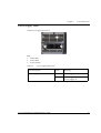
Power Supply Panel
P460 Power Supply Front Panel
1
3
2
Key
1
2
3
Status LED
Power inlet
Power switch
Table 5.8
Power Supply Status LED
LED Description
State
Meaning
Power Supply Status
Green
Power supply functioning
Orange
Power supply failure
Power supply off
Avaya P460 Installation and Maintenance Guide
33
Chapter 5
34
Avaya P460 Panels
Avaya P460 Installation and Maintenance Guide
Chapter 6
Maximizing Avaya P460 Availability
Introduction
In order to maximize availability of the Avaya P460 for applications such as VoIP,
you can deploy a variety of redundancy mechanisms.
This chapter describes the Supervisor module and I/O module redundancy and
power supply availability features.
M460ML-SPV Supervisor Module Redundancy
To enable supervisor redundancy, you need to install two M460ML-SPV Supervisor
Modules in a P460 Chassis. Ensure that one Supervisor module is “Active” and that
the second is “Standby”.
M460ML-SPV Supervisor Module Modes:
• Active – The Supervisor Module is operating
• Standby – This Supervisor Module is fully synchronized with the Active one and
can replace it in the case of failure.
• Halted – This Supervisor Module is not synchronized with the Active one and
cannot act as a standby module.
You can verify the Supervisor Module mode by:
• the ACT and OPR LED status (refer to Table 6.1)
• the show spv CLI command, or
• the P460 Manager.
Table 6.1
ACT and OPR LED Summary
ACT LED is...
OPR LED is...
M460ML-SPV Module mode
ON
ON
Active
ON
Blinking
Active
No fan module present
OFF
ON
Standby
OFF
Blinking
Halted or booting
Avaya P460 Installation and Maintenance Guide
35
Chapter 6
Maximizing Avaya P460 Availability
Configuring the Supervisor Modules for Active/Standby Operation
In order to operate in an Active-Standby configuration, the two SPVs must be
synchronized.
• If the Supervisor modules are not synchronized, one is Active and the other
Halted.
In this case you will need to synchronize them manually. See “Synchronizing
the Supervisor Modules Manually“ on page 36.
• Both Supervisor modules switching fabrics participate in switching/routing in
Active-Standby configuration only
• A Supervisor module which was Active stays Active after a chassis reset
One of the SPVs can operate as Standby automatically only if both of the following
conditions are fulfilled:
• The current chassis is the last one in which you inserted this SPV
• The current running SW images are the same version
Synchronizing the Supervisor Modules Manually
If the SPVs are not synchronized, you need to synchronize them manually using the
Avaya P460 CLI.
Note: Synchronization can be required for a complete synchronization also if the
SPVs are in an Active-Standby configuration. For example, when the SPVs boot
with the same SW but from different banks
1 Access the CLI. See Chapter 7, “Establishing Switch Access“
2 Enter the sync spv command from the Active Supervisor Module.
L This command transfers the following information from the Active Supervisor
module to the other Supervisor module:
— Firmware images
— Embedded Web image
— Preferred boot bank
— Chassis synchronization
L The transfer process can take up to 90 seconds.
36
Avaya P460 Installation and Maintenance Guide
Chapter 6
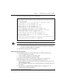
Maximizing Avaya P460 Availability
L The following screen capture shows the process:
P460-1(super)# sync spv
This command may overwrite the neighbor SPV software and
reset both SPVs
*** Confirmation *** - do you want to continue (Y/N)? y
Copying Bank A to the neighbor SPV ...
Copying Bank A to the neighbor SPV done
Copying Bank B to the neighbor SPV ...
Copying Bank B to the neighbor SPV done
Copying Embedded Web image to the neighbor SPV ...
Copying Embedded Web image to the neighbor SPV done
Setting boot bank of the neighbor SPV ...
Setting boot bank of the neighbor SPV done
Setting chassis sync on for the neighbor SPV...
Setting chassis sync on for the neighbor SPV done
SPVs are resetting.
Please wait till the process is finished. The SPVs will be
synchronized after the reset is completed
Note: After the transfer is finished, the Supervisor modules are reset automatically.
— After the reset the configuration files of the Active Supervisor Module are
copied to the Standby Supervisor Module.
L This process can take up to two minutes.
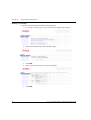
Configuration File Synchronization
Three configuration files are stored in the Supervisor module flash memory:
• Layer 2 configuration (L2-config)
• Layer 3 running configuration (running-config)
• Layer 3 startup configuration (startup-config)
If two Supervisor modules are present, the configuration is automatically
synchronized between the Active and Standby Supervisor modules.
• Initial configuration synchronization takes place after the boot: this process can
take up to thirty seconds.
• Layer 2 configuration changes are saved in both Supervisor modules when you
press Enter.
L The Supervisor module Ethernet outband interface configuration is not
synchronized between the modules.
Avaya P460 Installation and Maintenance Guide
37
Chapter 6
Maximizing Avaya P460 Availability
•
Layer 3 startup configuration is saved in the Standby SPV when you execute the
copy running-config startup-config CLI command. This
configuration is also saved in the Active SPV
L The Layer 3 running configuration is not saved in the Standby SPV
38
Avaya P460 Installation and Maintenance Guide
Chapter 6
Maximizing Avaya P460 Availability
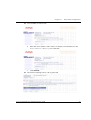
Redundant Power Supplies
The Avaya P460 supports automatic Power Supply redundancy and load-sharing.
Power supply redundancy is activated according to the number of PSUs and I/O
modules you have installed in the chassis.
Three PSUs are automatically configured in 2+1 redundancy mode.
If the installed power supplies can provide sufficient power for the switch, then an
additional power supply is automatically configured to operate in Redundancy
mode.
If the power budget requirement increases beyond the power available from the
non-redundant power supplies, then the additional power supply reverts to regular
mode.
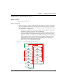
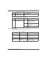
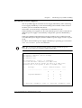
In order to check whether power supply redundancy is operating, you can use the
show environment power CLI command.
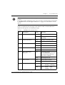
Note: The “Total Power drawn from the system” always includes the power
reserved for two supervisor modules and the fan module.
P460
PSU1
PSU2
PSU3
> show environment power
Capacity: 300 Watts (48V @ 6.25 Amps)
Capacity: none
Capacity: none
PSUs Configuration: 1
Total Power Available:
Total Power drawn from
Remaining Power in the
PSU/s , no redundancy.
300 Watts (6.25 Amps @ 48V)
the system: 229 Watts (4.77 Amps @ 48V)
system: 71 Watts (1.48 Amps @ 48V)
Slot
Card-Type
Active
----
--------------------
------- ------- ---------
3
Enabled Draws(W)
Fault
N
Y
0
Y
Y
48
5
N
Y
0
6
N
Y
0
4
avayaP460-M4648ML-T
-----
*- 2 SPVs power consumption: 68(W) x 2, Fans power consumption: 45(W)
Avaya P460 Installation and Maintenance Guide
39
Chapter 6
Maximizing Avaya P460 Availability
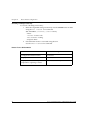
Calculating the Power Budget
You can also calculate how many PSUs you need in order to provide redundancy
for a specific configuration.
You need to add the power requirements for the I/O modules installed to the base
requirement of two Supervisor modules and one Fan module. If the total is less than
the power supplied by the number of PSUs installed, an additional PSU provides
redundancy.
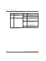
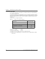
Table 6.2 shows a sample calculation:
Table 6.2
Sample Power Budget Calculation
Component
Requirement (W)
Fan module
45
2 x M460ML-SPV Supervisor Modules
2 x M4648ML-T I/O Modules
Total
136
96
277
Total power available:
300 W
Total power requirement:
277 W
An additional power supply will operate in redundant mode.
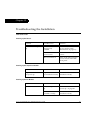
L Refer to “Power Requirements” on page 80 for power requirements for P460
components.
40
Avaya P460 Installation and Maintenance Guide
Chapter 7
Establishing Switch Access
Introduction
This chapter describes how to access the Avaya P460 CLI from the following
devices:
• A terminal to the serial port on the Supervisor Module
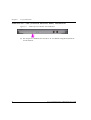
• A workstation running a Telnet session connected via an I/O module (Inband)
• A workstation running a Telnet session connected to the Console Fast Ethernet
port on a Supervisor module (outband)
• A remote terminal/workstation attached via a modem (PPP connection) to the
Supervisor Console Serial port. (Sideband)
Establishing a Console Connection with the P460
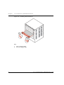
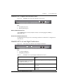
Figure 7.1
M460ML-SPV Supervisor Module Serial Console Port
Perform the following steps to connect a terminal to the P460 Serial Console port for
configuration of switch parameters:
1 Use the serial cable supplied to attach the RJ-45 console connector to the
Console port of the active M460ML-SPV module. Connect the DB-9 connector to
the serial (COM) port on your PC/terminal.
L The active Supervisor module is indicated by the ACT and OPR LEDs being lit.
2 Ensure that the serial port settings on the terminal are:
— 9600 baud
— 8 bits
— 1 stop bit
— no parity.
X If you reset or powered up the switch after connecting and configuring the
terminal, Welcome to P460 appears followed by the Login Name prompt.
L If the login prompt does not appear, press a key on the terminal.
3 Enter the default login: root.
X The Password prompt appears
4 Enter the user level password: root.
Avaya P460 Installation and Maintenance Guide
41
Chapter 7
Establishing Switch Access
Note: If you connect your terminal to the Standby SPV, you can get access to all the
CLI commands by opening a Session to the Active SPV. (See the Session command
on page 63).
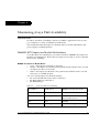
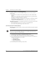
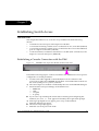
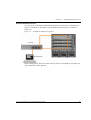
Establishing a Telnet Connection with the Switch (Inband)
Perform the following steps to establish a Telnet connection to the P460 for
configuration:
L You need to assign an inband interface IP address using a direct connection to
the console serial port before you can establish the Telnet session.
1 Connect your station to the I/O module (directly or via the network).
2 Verify that you can communicate with the P460 using Ping to the inband
interface IP of the P460. If there is no response using the Ping command, check
the IP address and default gateway of both the P460 and the station.
L The default subnet mask is 255.255.255.0.
3 Start a Telnet session:
— From the Microsoft Windows® taskbar of your PC click Start and then Run
or access the command prompt
— Start the Telnet session by typing: telnet <P460_IP_address>
For example: telnet 149.49.35.214
X The Login Name prompt is displayed
4 Enter the default name root
X The password prompt is displayed
5 Enter the password root in lower case letters.
L You can now configure the P460.
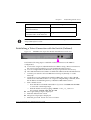
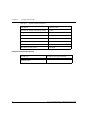
Inband Interface Connection CLI Commands
42
In order to...
Use the following command...
Configure the management
interface
set interface inband
Configure the management VLAN
ID
set inband vlan
Enable the inband interface
enable interface inband
Disable the inband interface
disable interface inband
Avaya P460 Installation and Maintenance Guide
Chapter 7
Establishing Switch Access
In order to...
Use the following command...
Display information on the device
network interfaces
show interface
Send an ICMP echo request packets
to another node on the network.
ping
Note: For more detailed information on the CLI commands, please refer to the
Avaya P460 Reference Guide
Establishing a Telnet Connection with the Switch (Outband)
Figure 7.2
M460ML-SPV Supervisor Module Fast Ethernet Console Port
Perform the following steps to establish a Telnet connection to the P460 for
configuration:
L You need to assign an outband interface IP address using a direct connection to
the console serial port before you can establish the Telnet session.
L You can configure the Fast Ethernet console port parameters if necessary.
L The outband interface should be on a different subnet from the inband interface.
1 Connect your station to the Fast Ethernet console port (directly or via the
network).
2 Verify that you can communicate with the P460 using “ping” to the outband
interface IP of the P460. If there is no response using the Ping command, check
the IP address and default gateway of both the P460 and the station.
3 Start a Telnet session:
— From the Microsoft Windows® taskbar of your PC click Start and then Run
or access the command prompt
— Start the Telnet session by typing: telnet <P460_IP_address>
For example: telnet 149.49.35.214
X The Login Name prompt is displayed
4 Enter the default name root
X The password prompt is displayed
5 Enter the password root in lower case letters.
Avaya P460 Installation and Maintenance Guide
43
Chapter 7
Establishing Switch Access
L You can now configure the P460.
L You can connect the Out-band interface to either of the Supervisor modules.
Outband Interface Connection CLI Commands
44
In order to...
Use the following command...
Configure the management
interface
set interface outband
Enable the outband interface
enable interface outband
Disable the outband interface
disable interface outband
Enable or disable the link
negotiation protocol on the Fast
Ethernet console port
set outband negotiation
Set the speed of Fast Ethernet
Console port
set outband speed
Set the duplex mode of the Ethernet
Console port
set outband duplex
Display information on the device
network interfaces
show interface
Display outband interface
parameters
show outband
Send an ICMP echo request packets
to another node on the network.
ping
Avaya P460 Installation and Maintenance Guide
Chapter 7
Establishing Switch Access
Redundant Outband Connections
You can create a redundant outband management connection by connecting both
Supervisor modules to the NMS via the Fast Ethernet interface by a switch (see
Figure 7.3).
Figure 7.3
Redundant Outband Connections
Switch
Workstation
In this configuration, the Active SPV will respond to its Out-band port and the port
of the other SPV will be ignored.
Avaya P460 Installation and Maintenance Guide
45
Chapter 7
Establishing Switch Access
Establishing a PPP via Modem Connection with the P460 (Sideband)
Overview
The Point-to-Point Protocol (PPP) provides a Layer 2 method for transporting multiprotocol datagrams over point-to-point links. Here only IP datagrams will be
exchanged, over a RS232 serial connection, between the P460 supervisor module
and a remote peer (such as Ethernet) via a modem and the telephone lines. This
provides remote access the sideband management interface of a P460 via a modem.
Sideband (PPP) Interface CLI Commands
46
In order to...
Use the following command...
Configure the device ppp interface
and control a PPP session
set interface ppp
Configure the shared secret used in
PPP sessions with CHAP
authentication
set ppp chap-secret
Set the time after which the system
automatically disconnects an idle
PPP incoming session
set ppp incoming timeout
Define the PPP authentication
method
set ppp authentication incoming
Set the baud rate used in PPP
sessions
set ppp baud-rate
Display the PPP parameters of the
active PPP session.
show ppp session
Display the authentication method
used for PPP sessions
show ppp authentication
Display the time after which the
system automatically disconnects
an idle PPP incoming session
show ppp incoming timeout
Display the baud rate used in PPP
sessions
show ppp baud-rate
Display the ppp configuration
show ppp configuration
Avaya P460 Installation and Maintenance Guide
Chapter 7
Establishing Switch Access
Setting Up Sideband (PPP) Connection Configuration
L You need to configure an IP address and netmask for the sideband interface
before you can establish a ppp link.
1 Connect a terminal to the Serial console port.
2 When you are prompted for a Login Name, enter the default name root.
3 When you are prompted for a password, enter the password root. You are
now in Supervisor Level.
4 At the prompt, type:
set interface ppp <ip_addr><net-mask>
with an IP address and netmask to be used by the Avaya P460 Supervisor
module to connect via its PPP interface.
L The PPP interface you configure with the set interface ppp command must be
on a different subnet from the inband and outband interfaces.
5 Set the baud rate, ppp authentication, and ppp time out required to match your
modem.
6 At the prompt, type:
set interface ppp enable
X The following is displayed:
Entering the Modem mode within 60 seconds...
Please check that the proprietary modem cable is plugged
into the console port
7 Use the DB-25 to RJ-45 connector to plug the console cable to the modem’s DB25 connector. Plug the other end of the cable RJ-45 connector to an
Avaya P460 Supervisor module RJ-45 port.
8 The Avaya P460 Supervisor module enters modem mode.
9 You can now dial into the switch from a remote station, and open a Telnet, ping
or SNMP management session to the PPP interface IP address.
L If you have two Supervisor modules installed, you can make a serial connection
to one SPV and configure the PPP parameters through one session and deploy
the PPP connection on the second Supervisor module.
Avaya P460 Installation and Maintenance Guide
47
Chapter 7
48
Establishing Switch Access
Avaya P460 Installation and Maintenance Guide
Chapter 8
Avaya MSNM P460 Manager
The P460 Manager provides the following features:
• Device Configuration - Viewing and modifying the different device
configurations.
• Virtual LANs - Viewing and editing Virtual LAN information.
• Link Aggregation Groups (LAGs) - Viewing and editing LAG information.
• Port Redundancy - Setting redundancy for ports in a P460 Switch.
• Port Mirroring - Setting up port mirroring for ports in a P460 Switch.
• Trap Managers Configuration - Viewing and modifying the Trap Managers
Table.
• Switch Connected Addresses - View devices connected to selected ports.
• Routing Manager - Viewing configurations of IP Routing protocols and general
information.
PC System Requirements for Running the Avaya MSNM P460
Manager
Minimum hardware and Operating System requirements are:
• Pentium II 400 Mhz-based computer with 128 Mb of RAM
• Screen resolution of 1024 x 768 pixels
• Microsoft Internet Explorer 5 or higher
• Microsoft Windows 2000 Workstation or Windows XP
• Sun Microsystems Java plug-in (supplied on the “Documentation and Utilities”
CD)
• Refer to the Release Notes for the exact version of the Java plug-in
Avaya P460 Installation and Maintenance Guide
49
Chapter 8
Avaya MSNM P460 Manager
Running the Avaya MSNM P460 Manager
Note: You should assign an inband or out-of-band interface IP address to the switch
before beginning this procedure.
1
2
Open your browser.
Enter the URL of the switch in the format http://aaa.bbb.ccc.ddd where
aaa.bbb.ccc.ddd is the inband or outband interface IP address of the
switch.
Note: The user name is “root”
The default password for read-only access is “root”
The default passwords for read-write access is “root”.
Note: The P460 Manager passwords are the same as those of the CLI. If you change
the passwords of the CLI then those passwords become active for Web management
as well. For further information on the passwords, please refer to Chapter 9.
X The welcome page is displayed.
Figure 8.1
50
The Welcome Page
Avaya P460 Installation and Maintenance Guide
Chapter 8
Avaya MSNM P460 Manager
X If you have the Java plug-in installed, the P460 Manager should open in a new
window (see Figure 8.2)
Figure 8.2
P460 Device Manager
— If you do not have the Java plug-in installed, follow the instructions on the
Welcome page that offers a variety of options to install the plug-in.
L You cannot configure Layer 3 parameters if you run the P460 Device Manager
over the Outband interface.
Avaya P460 Installation and Maintenance Guide
51
Chapter 8
Avaya MSNM P460 Manager
Installing the Java Plug-in
If the network manager has configured the system, the plug-in should be installed
automatically.
If the plug-in is not installed automatically, then you have three options for
installing it manually:
1 Installing from the P460 Documentation and Utilities CD
1 Close all unnecessary applications on your PC.
2 Insert the “Avaya P460 Documentation and Utilities” CD in the CD drive.
3 Open Windows® Explorer.
4 Open the embweb-aux-files\ folder on the CD
5 Double click on the plugin_a_b_c.exe file (a, b and c are the version
numbers of the plug-in).
6 Follow the on-screen instructions.
2 Install from the Avaya Web Site
Click on the link in the Welcome page.
3 Install from your Local Web Site
Click on the link in the Welcome page.
Note: This option is only available if the network manager has placed the files on
the local Web server.
52
Avaya P460 Installation and Maintenance Guide
Chapter 8
Avaya MSNM P460 Manager
Installing the On-Line Help and Java Plug-In on your Web Site
Note: This procedure is optional
Copying the help files and Java plug-in to a local Web server allows users to access
the on-line help for the Embedded Manager and enables automatic Installation and
Maintenance of the Java plug-in the first time the users tries to manage the device.
1 Copy the emweb-aux-files directory from the “Avaya P460 Documentation
and Utilities” CD to your local Web server. Please refer to your Web server
documentation for full instructions.
2 Define the URL in the P460 using the following CLI command:
set web aux-files-url //IP address/directory name
where //IP address/directory name is the location of the directory from
the previous step.
Documentation
The Device Manager comes with a detailed User’s Guide including a Glossary of
Terms and an overview of Data Communications concepts.
Avaya P460 Installation and Maintenance Guide
53
Chapter 8
54
Avaya MSNM P460 Manager
Avaya P460 Installation and Maintenance Guide
Chapter 9
User Authentication
Introduction
User Authentication is an important element of maintaining secure networks. It
prevents unauthorized network management and stops users from reconfiguring
network devices.
Local User Accounts
The Local User Account feature allows you to define up to ten accounts that can
manage a local (single) P460 switch. This simplifies administration on small
networks or where users do not log in to more than one switch.
Note: If you wish to define more than ten users per switch, or accounts for a user on
multiple switches, you should use RADIUS (Remote Authentication Dial-In User
Service). Refer to “RADIUS“ on page 57.
You need to define a user name, password and access level for each user.
Access Levels
In addition to the user name and password, you need to assign an access level for
each user. There are three access levels, each of which allows the user only to
perform certain actions. Refer to Table 9.1 for a brief description of each level.
Table 9.1
Access Level Descriptions
Level
Suitable for...
Allows...
Read-only
General users
Viewing of system parameter values.
Read-write
Site personnel
Access to configuration options.
Administrator
Network
administrator
As “read-write” plus configuring Local
User accounts and access to RADIUS
authentication configuration commands
Avaya P460 Installation and Maintenance Guide
55
Chapter 9
User Authentication
Note: If you wish to increase security, you can change the default user accounts and
SNMP communities.
Local User Account CLI Commands
In order to...
Use the following command...
Add a local user account and
configure a user (name, password
and access level)
username
To remove a local user account
no username
Display the username, password
and access type for all users on the
switch
show username
Note: The Web management passwords are the same as those of the CLI. If you
change the passwords of the CLI then those passwords become active for Web
management as well.
56
Avaya P460 Installation and Maintenance Guide
Chapter 9
User Authentication
RADIUS
Introduction to RADIUS
Local user accounts (see “Local User Accounts“ on page 55) are kept locally on the
switch. Therefore, if a site contains multiple Avaya Switches, it is necessary to
configure each switch with its own user accounts. Additionally, if for example a
'read-write' user has to be changed into a 'read-only' user, it will be necessary to
change all the 'read-write' passwords configured locally in every switch, in order to
prevent him to access this level anymore. This can be tedious at best, and at worst,
unmanageable. A better solution is to have all of the user login information kept in a
central location where all the switches can access it. Enter Remote Authentication
Dial-In User Service (RADIUS).
RADIUS (Remote Authentication Dial-In User Service) provides a mechanism for
such consolidation. A RADIUS authentication server is installed on a central
computer at the customer's site. On this server user authentication (account)
information is configured that provides various degrees of access to the switch. The
P460 will run as a RADIUS client. When a user attempts to log into the switch, if
there is no local user account for the entered user name and password, then the
switch will send an Authentication Request to the RADIUS server in an attempt to
authenticate the user remotely. If the user name and password are authenticated,
then the RADIUS server responds to the switch with an Authentication
Acknowledgement that includes information on the user's privileges
('administrator', 'read-write', or 'read-only'), and the user is allowed to gain access to
the switch. If the user is not authenticated, then an Authentication Reject is sent to
the switch and the user is not allowed access to the switch's embedded
management.
Avaya P460 Installation and Maintenance Guide
57
Chapter 9
User Authentication
Figure 9.1 illustrates the RADIUS authentication procedure:
Figure 9.1
RADIUS Authentication Procedure
User attempts login
Local User
account
authenticated in
switch?
No
Authentication
request sent to
RADIUS Server
User name and
password
authenticated?
Yes
Yes
No
Authentication Reject
sent to switch
User cannot access switch
embedded managegment
Perform log-in according
to user's priviliege level
to switch
RADIUS CLI Commands
58
In order to...
Use the following command...
Enable or disable authentication for
the P460 switch. RADIUS
authentication is disabled by
default
set radius authentication
Set a primary or secondary
RADIUS server IP address
set radius authentication server
Configure a character string to be
used as a “shared secret” between
the switch and the RADIUS server.
set radius authentication secret
Avaya P460 Installation and Maintenance Guide
Chapter 9
User Authentication
In order to...
Use the following command...
Set the RFC 2138 approved UDP
port number.
set radius authentication udp-port
Set the number of times an access
request is sent when there is no
response
set radius authentication retrynumber
Set the time to wait before resending an access request.
set radius authentication retry-time
Remove a primary or secondary
RADIUS authentication server
clear radius authentication server
Display all RADIUS authentication
configurations. The shared secrets
will not be displayed
show radius authentication
Avaya P460 Installation and Maintenance Guide
59
Chapter 9
User Authentication
Allowed Managers
With the Allowed Managers feature, the network manager can determine who may
or may not gain management access to the switch. The feature can be enabled or
disabled (default is disabled). When enabled, only those users that are configured in
the Allowed Managers table are able to gain Telnet, HTTP, and SNMP management
access to the switch.
You can configure up to 20 Allowed Mangers by adding or removing their IP
address from the Allowed Managers List.
Note: The identification of an “Allowed Manager” is done by checking the Source IP
address of the packets, thus if the Source IP address is modified on the way (NAT,
Proxy, etc.), even an “Allowed Manager” will not be able to access the P460.
Allowed Manager CLI Commands
60
In order to...
Use the following command...
When set to enabled - only
managers with ip address specified
in the allowed table will be able to
access the device
set allowed managers
Add/delete ip address of manager
to/from the allowed table
set allowed managers ip
Show the IP addresses of the
managers that are allowed to access
the device
show allowed managers table
Show whether the status of allowed
managers is enabled or disabled
show allowed managers status
Show the IP addresses of the
managers that are currently
connected
show secure current
Avaya P460 Installation and Maintenance Guide
Chapter 10
Configuration Defaults
Introduction
This chapter defines the default parameters for the P460 switch.
Default System Parameters
Table 10.1
Default System Parameters
Parameter
Default Value
All IP addresses
N/A (0.0.0.0)
Default gateway
N/A (0.0.0.0)
CLI timeout
15 minutes
User name
root
Password
root
PPP interface
Disabled
Out-of-band interface
Disabled
In-band interface
Disabled
In-band ARP Tx interval
5 seconds
Out-of-band ARP Tx interval
5 seconds
VLANs
1 on all ports
Spanning Tree
Enabled
Bridge priority for Spanning Tree
32,768
NTP server IP address
N/A
Time zone offset
0 hours
Timezone
GMT
Read-only SNMP community string
public
Avaya P460 Installation and Maintenance Guide
61
Chapter 10
Configuration Defaults
Table 10.1
Default System Parameters
Parameter
Default Value
Read-write SNMP community string
public
Trap SNMP community string
public
Number of SNMP retries
3
SNMP timeout
2,000
Intelligent multicast
Disabled
Boot bank
B
Broadcast storm control
Disabled
Configuration Default CLI Commands
62
In order to...
Use the following command...
Restore all parameters to the
default values
nvram init
Avaya P460 Installation and Maintenance Guide
Chapter 11
Basic Switch Configuration
Introduction
This chapter describes the parameters you can define for the chassis, such as its
name and location, time parameters, and so on.
Use the CLI commands briefly described below for configuring the display on your
terminal or workstation.
In order to...
Use the following command...
Open a CLI session to the
alternative SPV in the P460 chassis
session
Display or set the terminal width
(in characters)
terminal width
Display or set the terminal length
(in lines)
terminal length
Display or set the prompt
hostname
Return the prompt to its default
value
no hostname
Clear the current terminal display
clear screen
Set the number of minutes before
an inactive CLI session
automatically logs out
set logout
Display the number of minutes
before an inactive CLI session
automatically times out
show logout
Access Layer 3 configuration if not
logged in as supervisor (see
“Access Levels“ on page 55)
configure
Enter tech mode
L This command is reserved for
service personnel only
tech
Avaya P460 Installation and Maintenance Guide
63
Chapter 11
Basic Switch Configuration
In order to...
Use the following command...
Display the commands available at
your current location in the CLI
hierarchy
tree
System Parameter Configuration
Identifying the system
In order to make a P460 switch easier to identify, you can define a name for the
switch, contact information for the switch technician and the location of the switch
in the organization.
In order to...
Use the following command...
Configure the system name.
set system name
Configure the system contact
person
set system contact
Configure the system location
set system location
Operating parameters
You can use the following commands to configure and display the mode of
operation for the switch and display key parameters.
64
In order to...
Use the following command...
Configure the basic mode of
operation to either Layer 2 or
Routing
set device-mode
Display the mode of operation
show device-mode
Display system parameters
show system
Display module parameters
show module
Avaya P460 Installation and Maintenance Guide
Chapter 11
Basic Switch Configuration
Time Parameter Configuration
In order to...
Use the following command...
Restore the time zone to its default,
UTC.
clear timezone
Configure the time zone for the
system
set timezone
Configure the time protocol for use
in the system
set time protocol
Enable or disable the time client
set time client
Configure the NTP server address
set time server
Display the current time
show time
Display the time status and
parameters
show time parameters
Display the current time zone offset
show timezone
Get the time from the time server
get time
Feature License Configuration
Certain features in the Avaya P460 are activated by “Feature Licenses.” A sample
activation procedure for these features is described below:
Feature Activation
In order to benefit from the P460 routing capabilities, you need to purchase an
Avaya L480L3-License Routing License Key Certificate (catalog number 700255060)
for each P460 chassis .
Each Certificate is specific for:
• The module type.
• The required feature.
• The number of devices.
After you purchase a Feature Licence Key Certificate, you must obtain and activate
a Feature License Key.
Avaya P460 Installation and Maintenance Guide
65
Chapter 11
Basic Switch Configuration
Obtaining a License Key
To obtain a License Key that enables routing features:
1 Go to http://license-lsg.avaya.com and click “request new license”.
66
2
Enter the Certificate Key and Certificate Type.
3
4
Click Next.
Enter contact information (once per certificate)
5
Click Next.
Avaya P460 Installation and Maintenance Guide
Chapter 11
Basic Switch Configuration
X View number of licenses left.
6
Enter the serial number of the switch. To identify serial numbers use the
show chassis-identity CLI command: .
7 Click Generate.
X The feature-enabling license code is generated
Avaya P460 Installation and Maintenance Guide
67
Chapter 11
Basic Switch Configuration
Activating a Routing License Key
To activate a Routing License Key:
1 Enter the acquired Routing License Key into the M460ML-SPV module
using the set license CLI command.
set license [license] [featureName]
where:
license - license code
featureName - routing
2
and press Enter.
Check that the license is activated using the CLI.
Use the show license CLI command.
Feature License CLI Commands
68
In order to...
Use the following command...
Configure the feature license
set license
Display the feature license
show license
Display the switch identity
required for acquiring a license
show chassis-identity
Avaya P460 Installation and Maintenance Guide
Chapter 12
Troubleshooting the Installation
Introduction
Powering up the Chassis
Problem
Possible Cause
Solution
Chassis does not power
up
No PSU (Power
Supply Unit)
installed
Install PSU (see “PSU
(Power Supply Unit)
Installation“ on page 11)
PSU not connected to
power source
Connect PSU to the power
source
PSU not turned on
Turn on the PSU using the
power switch on the PSU
front panel
Problem
Possible Cause
Solution
Supervisor modules do
not power up
Supervisor module
not installed correctly
Ensure that the module is
installed correctly.
Problem
Possible Cause
Solution
Fans do not start
Chassis not powered
up
See “Chassis does not
power up“ on page 69
Fan module not
installed correctly
Check that Fan module is
installed correctly
Powering up the Supervisor Modules
Powering up the Fan Module
Avaya P460 Installation and Maintenance Guide
69
Chapter 12
Troubleshooting the Installation
Powering up the I/O Modules
Problem
Possible Cause
Solution
I/O modules do not
power up
No Supervisor
module installed
Install supervisor module
(see “Supervisor Module
Installation“ on page 14)
Supervisor module
not functioning
Replace supervisor module
Insufficient Power
Budget
Add PSUs
Remove un-needed I/O
modules or
Disable power to the
appropriate I/O slots. See
the set slot power
command
Rearrange I/O Modules to
reflect priority
I/O modules powered
down automatically
70
Power disabled to
I/O slot
Enable power to slot. See
the set slot power
command.
Fan module removed
for more than five
minutes
Re-insert fan module
Power down chassis
Power up chassis
Avaya P460 Installation and Maintenance Guide
Chapter 12
Troubleshooting the Installation
Supervisor Module does not Boot
Problem
Possible Cause
Solution
OPR LED does not
light.
Supervisor Module
has not booted.
Use the “ASB” (Alternate
Software Bank) button to
switch to the second
firmware bank.
• Press and hold the “L”
and “R” buttons to reset
the switch.
X The switch will reset.
• Immediately press the
ASB button by gently
inserting a small object
such as a bent paper clip
into the hole.
• Keep the ASB button
pressed until the reset
procedure has
completed.
If a second software version
is present, the SPV modules
will then boot from the
alternate software image
bank.
Avaya P460 Installation and Maintenance Guide
71
Chapter 12
72
Troubleshooting the Installation
Avaya P460 Installation and Maintenance Guide
Chapter 13
Maintenance
Introduction
This chapter provides some basic information for downloading firmware to the
Avaya P460. For issues that are not covered in “Troubleshooting the Installation“ or
this chapter, please contact your Avaya representative.
Caution: Please refer to “Before you Install the Avaya™ P460“ for safety information
before proceeding.
Replacing I/O Modules
See “I/O Module Installation” on page 16.
Replacing Supervisor Modules
One Supervisor Module in the Switch
When you remove the Supervisor module, the switch is turned off. The switch is
turned on after you insert a replacement Supervisor module.
Two Supervisor Modules in the Switch
If you remove the Active Supervisor module, the
Configuring the Supervisor Modules for Active/Standby Operation
In order to operate in an Active-Standby configuration, the two SPVs must be
synchronized.
• If the Supervisor modules are not synchronized, one is Active and the other
Halted.
In this case you will need to synchronize them manually. See “Synchronizing
the Supervisor Modules Manually“ on page 36.
• Both Supervisor modules switching fabrics participate in switching/routing in
Active-Standby configuration only
• A Supervisor module which was Active stays Active after a chassis reset
Avaya P460 Installation and Maintenance Guide
73
Chapter 13
Maintenance
One of the SPVs can operate as Standby automatically only if both of the following
conditions are fulfilled:
• The current chassis is the last one in which you inserted this SPV
• The current running SW images are the same version
Firmware Download
You can perform software download using the copy tftp command (see page 26
of the Avaya P460 Reference Guide) or the Avaya Software Update Manager (part of
the Avaya™ Multiservice Network Manager Suite).
L You can obtain the latest firmware from the Avaya support site at
http://www.support.avaya.com
Introduction
Each P460 Supervisor module has two firmware image banks (“A” and “B”) and
one Device Manager (Embedded Web) bank.
The download is on a per-chassis basis and the firmware is automatically loaded
into the standby Supervisor module (if configured) in addition to the active
Supervisor module.
L Firmware is not downloaded to a halted Supervisor module.
You download the firmware to each bank separately via the CLI. The download
progress is shown on the screen.
Preferred Bank
You can choose which firmware bank to boot from (preferred bank) using the set
boot bank command.
L Changing the preferred bank affects both SPVs.
Booting from the Alternate Firmware Bank
Push the ASB button together with both function switches on the SPV front panel to
boot from the alternate SW bank.
L If the SPVs were running in a Active-Standby configuration and ASB caused
SW incompatibility between the SPVs, the Standby SPV will switch to Halted
mode.
74
Avaya P460 Installation and Maintenance Guide
Chapter 13
Maintenance
Firmware Download CLI Commands
In order to...
Use the following command...
Set the default boot bank
set boot bank
Download firmware to Bank A
copy tftp SW_imageA
Download firmware to Bank B
copy tftp SW_imageB
Copy Device Manager (Embedded
Web) firmware
copy tftp EW_archive
Show the default boot bank
show boot bank
Configuration File Management
You can transfer the Layer 2 parameters to or from the current NVRAM running
configuration file to a TFTP server.
This feature permits you to make a backup of the parameters. You can then use that
file to configure other Avaya P460 switches without re-entering all the parameters
manually.
L To use this feature, you need to have an active tftp server, and to create a file
into which to download the data.
If Avaya MultiService Network Manager is running, you do not require an
additional TFTP server.
Configuration Management CLI Commands
In order to...
Use the following command...
Upload the Layer 2 parameters
from the current NVRAM running
configuration to a file via TFTP
copy l2-config tftp
Update the Layer 2 parameters in
the current NVRAM running
configuration from a file via TFTP
copy tftp l2-config
Show the Layer 2 configuration file
show l2-config
Avaya P460 Installation and Maintenance Guide
75
Chapter 13
76
Maintenance
Avaya P460 Installation and Maintenance Guide
Chapter 14
Standards
Introduction
The Avaya P460 complies with the following standards:
IEEE
•
•
•
IEEE 802.3x
IEEE 802.1q/p
IEEE 802.1D
Flow Control
VLAN Tagging and 802.1p compatible
Spanning Tree protocol
IETF
Layer 2
• RFC-0868 Time Protocol
• RFC-1155 Structure and identification of management information for TCP/IPbased internets
• RFC-1157 Simple Network Management Protocol (SNMP)
• RFC-1213 MIB-II
• RFC-1314 Bridge MIBs for STP, and for CAM contents
• RFC-1332 PPP Internet Protocol Control Protocol (IPCP)
• RFC-1334 PPP Authentication Protocols (PAP & CHAP)
• RFC-1493 Bridge MIB for Spanning Tree
• RFC-1661 Point-to-Point Protocol (PPP)
• RFC-1757 RMON (support for groups 1,2,3 and 9)
• RFC-1769 Simple Network Time Protocol (SNTP)
• RFC-2613 SMON
• RFC-2674 Bridge MIB Groups - dot1dbase and dot1dStp fully implemented.
• Support for relevant MIB ogjects: dot1q (dot1qBase, dot1qVlanCurrent)
• RFC-2863Interfaces Group MIB
• RFC-2865Remote Authentication Dial In User Service (RADIUS)
• MIB-II - RFC 1213
• Bridge MIB for Spanning Tree - RFC 1493
• RMON - RFC 1757
• SMON - RFC 2613
Avaya P460 Installation and Maintenance Guide
77
Chapter 14
Standards
Layer 3
• RFC-791 Internet Protocol
• RFC-792 Internet Control Message Protocol
• RFC-826 Ethernet Address Resolution Protocol
• RFC-894 Standard for the transmission of IP datagrams over Ethernet
• RFC-922 Broadcasting Internet datagrams in the presence of subnets
• RFC-950 Internet Standard Subnetting Procedure
• RFC-951 Bootstrap Protocol
• RFC-1027 Using ARP to implement transparent subnet gateways
• RFC-1058 Routing Information Protocol
• RFC-1112 Host Extensions for IP Multicasting
• RCF-1122 Requirements for Internet Hosts - Communication Layers
• RFC-1533 DHCP Options and BOOTP Vendor Extensions
• RFC-1534 Interoperation Between DHCP and BOOTP
• RFC-1541 Dynamic Host Configuration Protocol
• RFC-1542 Clarifications and Extensions for the Bootstrap Protocol Information
• RFC 1583 OSPF Version 2
• RFC-1624 Computation of the Internet Checksum via Incremental Update
• RFC 1723 RIP Version 2 Carrying Additional Information
• RFC 1724 RIP Version 2 MIB Extension
• RFC-1812 Requirements for IP Version 4 Routers
• RFC-1850 OSPF Version 2 Management Information Base
• RFC-2021 RMON II (not supported by P333R-LB)
• RFC-2096 IP Forwarding Table MIB
• RFC-2338 Virtual Router Redundancy Protocol
• RFC-2474 Definition of the Differentiated Services Field (DS Field)
• Internet Draft - draft -ietf-vrrp-mib-08 Definitions of Managed Objects for the
Virtual Router Redundancy Protocol
Routing
•
•
•
•
•
•
78
RIP1
RIP2
OSPF
ARP
ICMP
DHCP/BOOTP Relay
Avaya P460 Installation Guide
Chapter 15
Specifications
Physical
Height
10U (17.5", 444.5 mm)
Width
17.4" (442 mm)
Depth
15" (375 mm)
Weight
Chassis + backplane
13 kg (28.6 lb.)
Fan module
2.3 kg (5.1 lb.)
Supervisor module
2.0 kg (4.4 lb.)
300W AC PSU
3.85 kg (8.5 lb.)
PSU blanking panel
0.3 kg (0.7 lb.)
“Minimum Configuration”
• Chassis + backplane
• Two PSU blanking plates
• One PSU
• One Supervisor Module
• fan module
22 kg (48 lb.)
Fully populated chassis
• Chassis + backplane
• Three PSUs
• Two Supervisor Modules
• fan module
• Four I/O Modules
at least 45 kg. (100 lb.)
Avaya P460 Installation and Maintenance Guide
79
Chapter 15
Specifications
Power Requirements
MPS4603-AC Power Supply
Input voltage
100 to 240 VAC, 50 or 60 Hz
Power dissipation
300 W max
Input current
3.9 A at 100 VAC
1.5 A at 240 VAC
Inrush current
15 A at 100 VAC (max.)
30 A at 240 VAC (max.)
Components
Fan Module
45 W
M460ML-SPV
68 W
Avaya M4648ML-T
48 W
Avaya M4648ML-T-2G
70 W
Avaya M4612ML-G
59 W
Environmental
Operating Temp.
23 to 122°F (-5 to 50°C)
Rel. Humidity
5% to 95% non-condensing
Safety
•
•
•
•
•
•
80
UL for US approved according to UL60950 Std.
C-UL (UL for Canada) approved according to C22.2 No.950 Std.
CE for Europe approved according to EN 60950 Std.
EN60825-1
Laser components are Laser Class I approved:
— EN-60825-2/IEC-825 for Europe
— FDA CFR 1040 for USA
Overcurrent Protection: A readily accessible Listed safety-approved protective
Avaya P460 Installation and Maintenance Guide
Chapter 15
Specifications
device with a 16A rating must be incorporated in series with building
Installation and Maintenance AC power wiring for the equipment under
protection.
EMC Emissions
Approved according to:
• US - FCC Part 15 sub part B, class A
• Europe - EN55022 class A and EN61000-3-2 and EN61000-3-3
• Japan - VCCI Class A
• NEBS GR-1089-CORE
Immunity
Approved according to:
• EN 55024
Transportation
•
•
NEBS GR-63-CORE
NTSB
Avaya P460 Installation and Maintenance Guide
81
Chapter 15
Specifications
Catalog Numbers
Table 15.1
82
Avaya P460 Catalog Numbers
Product
Description
Material
Code
PEC
Code
Avaya P460-CH
P460 chassis
7000254998
4548-001
Avaya M460ML-SPV
P460 supervisor module
700255011
4548-002
Avaya M4648ML-T
P460 Multilayer 48 x 10/
100BASE-T (RJ-45) module
700255029
4548-003
Avaya M4648ML-T-2G
P460 Multilayer 48 x 10/
100BASE-T (RJ-45) + 2 x GBIC
(SFP) module
700255037
4548-004
Avaya M4612ML-G
P460 Multilayer 12 x GBIC
(SFP) module
700255045
4548-005
Avaya M460-FAN
P460 fan module
700255052
4548-006
Avaya L480L3-License
P460 Layer 3 license
700255060
4548-007
Avaya MPS4603-AC
P460 330W AC PSU
700255078
4548-008
Avaya P460ML-CFG
P460 switch basic
configuration (SPV, PSU, fan)
700255003
4548-009
Avaya P460 Installation and Maintenance Guide