1
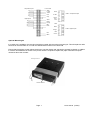
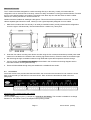
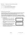
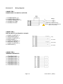
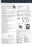
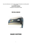
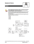
INSTALLATION AND USER’S MANUAL External and internal temperature recorders DataCOLD 500 T/R Carrier Transicold Europe – 10, Bd de l’Oise – 95031 Cergy Pontoise Cédex – France Carrier Transicold North America, 700 Olympic Drive, Athens, Ga. 30601 - U.S.A. Carrier Refrigeration Operation 2003 Printed in France 02-03 / 62-61138-20 INTRODUCTION This manual is a guideline for the installation and use of the DataCOLD 500 T/R temperature recorders. To avoid loss of warranty coverage due to incompetent installation it is most essential to follow the instructions and recommendations of this manual. DataCOLD 500 T/R recorders are developed and produced to conform to the applicable European and National norms for the delivery of chilled and frozen foods in transport vehicles. DataCOLD 500 T/R recorders are tested and approved to the European EN12830 specification meeting the objectives of directives 92/1/EU and 93/43/EU and "e" mark approved following directive 95/54/CE. DataCOLD 500 T/R can provide evidence of correct temperatures for every trip in the form of a delivery ticket, numerical or graphical print out. All data is stored with a date/time stamp in a large flash memory. Data will not be lost if power supply is disconnected. The real time clock is powered by an internal back-up battery. The two recorder versions DataCOLD 500 T/R differ in looks. The R-Version is suitable for in-cab installation and the T-Version for outside mounting on a trailer. Both versions are available with or without integrated printer. A printer can be retrofitted at any time, the recorder has been designed already with hardware- and software. DataCOLD 500 R The R-Version has been developed for mounting in the truck cab. The chassis of the recorder meets the dimensions of a DIN car radio and can be easily mounted in a free available radio slot. On the back side the connectors are designed for up to 4 Temperature sensors and 4 digital inputs, a power supply and digital outputs and a serial communication connector ( RS-232 ). If no free radio slot is available, the use of the optional universal mounting kit is strongly recommended. DataCOLD 500 T The T-Version has been developed especially for mounting outside on a body or trailer. The unit is fixed into a water proof enclosure. As on the R-version the connectors are on the back of the unit. Cabling is installed through watertight cable glands. Both products are produced by Carrier Transicold in Germany. Carrier Transicold has a policy of continued development and improvements. Therefore products, manuals and technical information are subject to change without prior notice. Page 2 62-61138-20 (02/03) TABLE OF CONTENTS 1 GENERAL DESCRIPTION................................................................................................................................ 4 1.1 LCD Display.................................................................................................................................................. 4 1.2 Keyboard ...................................................................................................................................................... 4 1.3 Printer ........................................................................................................................................................... 5 2 INSTALLATION................................................................................................................................................. 5 2.1 Positioning Connections ............................................................................................................................ 5 2.2 Mounting....................................................................................................................................................... 6 2.3 Connectors................................................................................................................................................... 8 2.4 Wiring..........................................................................................................................................................10 2.5 Configuration .............................................................................................................................................10 2.6 Final testing Standard Installation...........................................................................................................11 2.7 Supplementary installation.......................................................................................................................11 3 USER MENU'S ................................................................................................................................................12 3.1 Print menu ..................................................................................................................................................12 3.2 Alarm menu ................................................................................................................................................14 3.3 User settings ..............................................................................................................................................15 3.4 Status menu ...............................................................................................................................................16 4 PARAMETER MENU.......................................................................................................................................17 Menu 5 : Temperature inputs settings ..........................................................................................................17 Menu 6 : Digital inputs settings .....................................................................................................................19 Menu 7 : Compartment settings ....................................................................................................................19 Menu 8 : Alarm settings..................................................................................................................................20 Menu 9 : Printer settings ................................................................................................................................20 Menu 10 : General settings ..............................................................................................................................21 Menu 11 : Communication settings.................................................................................................................21 5 ACCESSORIES AND SPARE PARTS ...........................................................................................................23 Enclosure A Technical data ...............................................................................................................................25 Enclosure B Replace paper roll.........................................................................................................................26 Enclosure C Factory settings ............................................................................................................................27 Enclosure D Failure codes .................................................................................................................................28 Enclosure E Wiring diagrams............................................................................................................................29 Page 3 62-61138-20 (02/03) 1 General description The control panel of the DataCOLD 500 T/R consists of three main components: 1- LCD Display 2- Key board 3- Printer 1.1 LCD Display The display has four lines of information, showing the following content in the operating mode: Line 1: Alarm active; temperatures, status of the digital inputs Line 2: Rotating display of each temperature to an accuracy of 1 decimal point with sensor name. Line 3: Day, date and time and indication summer/wintertime NOTE: Date will be displayed as dd/mm/yyyy (as shown) Line 4: Description of the actual button functions In every other mode the content of the display is dependent on the actual menu in use. 1.2 -23 –12 –08 –15 ✴ 1:Return air –22.8 Wednesday 21/06/2000 13:47:05 W Print Alarm Menu Status Keyboard DataCOLD 500 T/R are completely menu controlled. All functions can be carried out via the four colored buttons (like printing, activate alarms or change parameters). The actual function of the buttons are always displayed on the bottom line. To navigate through the menu’s and change settings, two different kinds of button functions are applicable. To navigate through the menu’s and to select parameters in the edit mode, use the buttons as described below: Blue Yellow Green Red ↑ < ↓ > edit accept <-menu <- cncl Next menu point In edit mode: Next choice from table Previous menu point In edit mode: Previous choice from table Menu select, change to edit mode or one menu level down In edit mode: accept input and go to next menu point One menu level up In edit mode: Cancel changes and displays the non changed value. Press and hold for 2 seconds to cancel changes and go back to previous menu. When entering free programmable text, like names, the button functions are as follows: Blue Yellow Green Red Blue + Yellow ↑ ↓ < > <- cncl Green + Red accept Next character from the list Previous character from the list One character to the left One character to the right Cancel changes and displays the non changed value. Press and hold for 2 seconds to cancel changes and go back to previous menu. Accept input and go to next menu point. Page 4 62-61138-20 (02/03) 1.3 Printer The thermal printer is installed in the right side of the recorder. Due to the so called “Plug and Play concept” the printer can be retrofitted, at any time, without disconnecting the recorder from power. For retrofit, the existing mechanism will be exchanged for a mechanism with printer. To remove the printer or the housing, press lightly the release bar on the right hand side under the housing. The whole mechanism can be slid out carefully. Warning: In the T-version the printer module must be disconnected via a cable connector. When inserting the printer module, slide it in carefully until the lock catches. Note: a print out must be torn downwards over the edge of the bottom plastic part. A colored line on the last few feet (meter) of a roll indicates that the paper roll needs to be replaced. (Enclosure B ) 2 Installation In general DataCOLD 500 T/R Temperature recorders are supplied with all required components for a standard installation. A standard installation includes the mounting of the unit itself and mounting and connecting two Temperature sensors. Optionally 2 extra sensors and up to 4 digital (status) inputs can be connected. The main steps of the installation are described in the following chronological order. 2.1 Positioning Connections Temperature sensors DataCOLD 500 T/R temperature recorders can only be used with temperature sensors supplied with the DataCOLD 500 T/R package. Before the installation it is necessary to determine how many measurement points are required to retrieve the desired information. Only by an optimal choice of the number and the position of the sensors, can a sensible conclusion be drawn of the air temperature in an entire compartment. The following items must be observed when planning: - The Temperature sensor should not be mounted in a location without air circulation. - The sensor position should be protected against bumping of load, doors, etc.. - The beam of light from the interior light must have a minimum distance of 18 inches (0,5m) to the sensors. - At least one sensor per compartment and also one sensor in the air return is recommended. The best position of a compartment sensor is in the middle under the ceiling at about 1/3 of the compartment length from the back. - The compartment sensor should be mounted with the Carrier protection guard. This will allow sufficient air circulation around the sensor. Supply air sensor Remote sensor Return air sensor Door switch DataCOLD T-version Page 5 62-61138-20 (02/03) Digital Inputs The digital inputs allow control and registration of doors (open/close) or defrost or refrigeration (on/off) or any other digital input information following the configuration of the recorder. By configuring the parameters the interpretation of the corresponding status can be distinguished. Power supply The power supply can be connected directly to the vehicle or Carrier Unit battery. The included 3A (T) floating fuse must be fitted in the +power line direct as close as possible to the power connection. The DataCOLD 500 T/R recorders are suitable for a voltage between 10 - 36 Volt DC. 2.2 Mounting The installation set of the DataCOLD 500 T/R recorder contains almost all components, required for a standard installation with two temperature sensors. In addition to that some small materials like Silicon kit, PVC-conduit and fixing materials for cable mounting are required. - Preferably use, for both outside and inside walls the existing cable conduit. Alternatively use self adhesive cable conduit. All drilled holes needs to be sealed with a suitable sealant. - For future calibration requirements, it is advisable to allow enough spare cable to enable the sensor to be lowered to the floor. DataCOLD R-Version The R-version is designed to be mounted within the cab of a vehicle in a DIN radio slot. The R-version is retained in the mounting cage by spring locking plates fitted to each side. Fix the mounting cage by inserting it into the slot and bending the fixing blades to secure it in the facia. Slide the recorder into the cage until it locks into position. Once fitted into the cage, the removal procedure is to insert the keys provided into the keyways at each side of the front face of the recorder to release the locks. 1. Select a suitable position for the DataCOLD, for example a free car radio slot in the dashboard or above the driver. If there is no free slot we recommend to use the optional mounting kit. The mounting kit can be fitted as shown below on top or underneath the dashboard. 2. Next, push the mounting frame into the slot and bend the metal flaps to secure its position. 3. Then install the sensors from the body to the driver’s cab. Please make sure to fit the cables along the chassis with the harness so that they won’t be broken when tilting the cab. 4. Take the connector blocks off the back of the instrument and fix the cables and connect the power supply directly to the battery according to the wiring diagram section. 5. Finally, before pushing the instrument into the slot, we recommend to test the function and to do a printout. Optional junction box When installing more than two sensors in case of a R-Version it is recommended to use a junction box making the installation simpler. This way of installation is using one multi-core cable to connect the recorder with the junction box. Inside the junction box the individual sensors and digital inputs are connected. Because pin 1, 3, 5 and 7 of the sensor inputs are linked via ground, only one of these pins needs to be connected. For the digital inputs the same is applicable for pin 2, 4, 6 and 8. Page 6 62-61138-20 (02/03) 12 Core cable Temperature inputs White Lt. blue White Yellow Pink Grey Digital inputs Violet Lt. Blue CON4 – Temperature inputs Yellow Grey Pink Brown Orange Blue Green Violet Brown Orange Red Black CON3 – Digitals inputs Blue Green Optional Mounting kit If no radio slot is available, the recorder should be mounted with the optional mounting kit. This will replace a radio slot and can be fixed either on or under the dashboard as well as on the back wall. Ensure that the position chosen allows the driver to see the display and operate the operator keyboard. In addition it must be remembered that access to the printer drawer is required to replace the paper roll and this requires clearance above the recorder. Mounting enclosure Key DataCold R-Version Page 7 62-61138-20 (02/03) DataCOLD T-Version The T-Version has been designed for outside mounting directly on the body. Usually it is fixed under the refrigeration unit on the front side of the body, where it is easily accessible. For fixing proceed as follows: First hold the box in the desired position and mark the mounting holes. Next step is to drill the holes so that the rubber sleeves fit in exactly and the box can be screwed on. Cables should be installed via watertight cable glands. This avoids moisture penetration into the box. For each cable a separate gland should be used, unless you use a gland especially designed for more cables. 1. Mark the four holes at the front of body in an easily accessible location (usually underneath the refrigeration unit to the right or left hand side). Then drill holes with a ∅ 25/64 inch (10mm) drill. 2. Insert the four rubber mounting nuts. Mount recorder using the four screws and washers provided (note metal washer to be located on the outside of the mounting lug fixed to the box). Ensure screws are screwed in tight. 3. Drill hole large enough at suitable location through bulkhead to pass the temperature sensors through. 4. Connect power cable directly to the battery as described in the connection and wiring diagram section. Recorder will start recording automatically. 5. Ensure all holes drilled through body are sealed with a suitable silicone sealer. 2.3 Connectors Since both versions are provided with identical PCB’S, the connections are the same for both versions. On the back of the recorder you will find four connector blocks . Each of them are described in detail in the next paragraphs. Connector CON 1 (Power supply and outputs) - Power supply Connect power supply on pin 1 (+) and pin 2 (-) directly to the battery. The recorder is suitable for a voltage between 10 - 36 Volt DC. Power consumption when printing is 25W. Page 8 62-61138-20 (02/03) WARNING : DISCONNECT THE RECORDER FROM THE BATTERY IF THE REFRIGERATION UNIT IS NOT USED FOR MORE THAN TEN (10) DAYS. Page 9 62-61138-20 (02/03) - Display background lighting (preferable for the R-Version) Usually the display background light switches on after pressing any key and switching off automatically after 30 seconds. When a permanent background light is required while driving connect pin 3 to a vehicle ignition +signal. WARNING : NEVER CONNECT DIRECT TO THE BATTERY. - Alarm outputs Pin 4 and 5 are digital alarm outputs, pin 4 for a temperature alarm and pin 5 for a status alarm. Both outputs switch to ground in case of an alarm situation and are limited to 1A output current. Connector CON 2 (serial port) Connector CON 2 is a serial communication port. This port can be used for a permanent connection with the microprocessor of the Carrier Unit. Connector CON 3 (digital inputs) DataCold 500 T/R recorders offer the possibility to connect up to 4 digital inputs. Pin 1-8 are accordingly marked with D1–D4 (D1 = Pin 1+2, …). At every opening or closing of the input circuit a status change will be recorded into memory, but only if the input has been activated and configured correctly in the parameter settings. All four inputs as standard are de-activated. The following functional names are pre-programmed: D1 = Refrigeration, D2 = Back door, D3 = Defrost, D4 = Side door. There is also a free text choice to enter a custom name on each digital input. For these digital inputs the polarity must be wired correctly. Pin 2, 4, 6 and 8 are internally connected to ground. Pin 1, 3, 5 and 7 are signal inputs. Connector CON 4 (temperature inputs) DataCold 500 T/R recorders offer the possibility to connect up to 4 temperature sensors. Pin 1-8 are accordingly marked with T1–T4 (T1 = Pin 1+2, …). Pin 2, 4, 6 and 8 are signal inputs and pin 1, 3, 5 and 7 are internally connected to ground. The polarity of the sensor cable is not relevant. In the factory setting input 1 and 2 are activated and pre-programmed as follows: T1=Return air, T2=Rear. 2.4 Wiring Refer to the Enclosure E “Wiring diagrams“ to connect: • Power supply • Alarm outputs ( if installed ) • Ignition key ( if permanent backlight needed ) • Analog sensors • Digital sensors • RS-232 of the refrigeration unit micro ( if installed ) 2.5 Configuration After finishing the physical installation of the temperature recorder it should to be configured. All parameters are stored in a parameter file. After every standard installation a number of parameters need to be either checked or changed. Time and date are directly accessible in the user menu, all other settings are accessible via the PIN code protected parameter menu. ( Factory settings, see ENCLOSURE C) • • • • • Time and date, Menus 3.1 and 3.3 Temperature inputs, Menu 5, On input T1 ‘Return air’ and on input T2 ‘Rear’ is pre-programmed. Both inputs are also activated for both recording and printing. Sample rate, Menu 10.2 standard on 10 minutes Vehicle ID, Menu 10.3 Header text, Menu 10.4 normally used for company name Page 10 62-61138-20 (02/03) Changing the language 1. Press the green key and select menu 3.4 with ↑ ,↓ . 2. Press again the green key to edit (enter) the menu 3.4. 3. Select the desired language with < …> and validate with the green key. 4. Press the red key to return to the normal display. Programming the vehicle ID No. and the customer’s name 1. Press and hold for two seconds the green key to get into the configuration menu. 2. Enter the PIN code 1111 by pressing the blue key four times. 3. Select Menu 10.3. (Vehicle ID) and press the green key to enter the edit mode. 4. Now enter the vehicle ID No. by using the 4 Keys (↑ ,↓ next character from list / < , > one character to the left or to the right). 5. To confirm the input press the green < and red > keys together. 6. Select Menu 10.4 to enter the customer name (Header text). Operation is similar to vehicle ID. 7. Press the Red Key to return to the normal display 2.6 Final testing Standard Installation The next points are subject to a final check after every installation: - Power supply The supplied power voltage is between 10V and 36V DC and protected with the 3A floating fuse. The power supply must be sufficient to offer 25W (can be checked by attempting printing). - Display/keyboard The display background light must switch on after pressing any key (except if using the permanent background light function) and an acoustic signal audible. The display shows the actual temperatures of the activated temperature inputs. - Temperature sensors After approx. 5 minutes the temperature must be correctly displayed. A value of –40°F (-40°C) indicates the possibility of a non connected sensor or a cable failure. A value of +122°F (+50°C) indicates a possible short between the connector pins. 2.7 Supplementary installation The next points are subject to a check if applicable: - Printer Test the printer by printing any ticket. - Digital inputs For each activated status input, a small box appears in the top right hand of the display (pre-defined symbol, indicating that the corresponding input has been activated). When the status of the input changes to ‘active’ the box will change into a symbol suiting to the function of this input. (for example Refrigeration ON shows ‘✽’). - Alarm signal The internal alarm signal (persistent buzzer) sounds as soon a pre-programmed temperature limit has been exceeded. At the same time an external signal is activated on the 5-pin connector block and the corresponding temperature input on the display will flash. The internal signal buzzer can be switched of by pressing the yellow (Alarm) key. The external signal and the flashing display will only stop after the temperature is back within the programmed limits. Page 11 62-61138-20 (02/03) 3 User menu's DataCold 500 T/R have four different user menu’s, which are directly accessible via the keyboard: 1. 2. 3. 4. Print menu Alarm menu User settings menu Status menu 3.1 Print menu Press Blue button. The last selected print choice will be displayed. Printing Print delivery ticket starts after 2 seconds. Repeatedly pressing the Blue button will scroll between the available printouts, delivery ticket, graphical- and numerical ticket. By pressing the Blue button for more than 2 seconds the following menu’s will be entered: 3.1.1 Select compartment to print. After pressing [edit] you can toggle with [↑], [↓] between the available compartments and select with the green button [accept] the required one. 3.1.2 Print event report By pressing the Green button [accept] printing of the event report will start. 1.1 Select compartment to print COMP.1 ↑ Print parameter report By pressing the Green button [accept] the parameter report will be printed after entering the correct PIN code. 3.1.4 Set print date With [edit] you can select a historical date for printing. After confirmation of the date with[accept] you can select the required report with the Blue button. Printing starts with a delay of 2 seconds. edit <-menu 1.2 Print event report ↑ 3.1.3 ↓ ↓ accept <-menu 1.3 Print parameter report ↑ ↓ accept <-menu 1.4 Set print date (01-01-2000) ↑ ↓ edit <-menu The next options from menu 1.5 until 1.8 can be switched on or off for the user by the supervisor. 3.1.5 Delivery ticket setting 1.5 Delivery ticket setting actual value With [edit] you can set the desired information printed on the delivery ticket. You can select ‚actual value‘, ‚actual + average‘ or ‚actual, average and ↑ ↓ edit <-menu min-max values. 3.1.6 Print time period This option is used in combination with ‘Day start- and end time’ in order to determine the time period of the various print reports. A print out starts from the actual time and prints back for the number of hours set in this parameter, but not further as the ‘Day start time’ set in the next menu. If the Page 12 1.6 Print time period (10 hour) ↑ ↓ edit <-menu 62-61138-20 (02/03) ‘Print time period’ is set to “0 hour“ only the ‘Day start time’ is applicable. Page 13 62-61138-20 (02/03) 3.1.7 Day start time A print out starts from the actual time and goes backwards until the time set in this parameter, unless the ‘Print time period’ is shorter. If the ‘Day start time’ is set to “00:00” only the ‘Print period time’ is applicable. This allows you to print back to a maximum of 24 hours. 3.1.8 Day end time This option is only used when printing a historical date. The print will start with the time set in this option and goes backwards until the required ‘Day start time’. The ‘Print time period’ is not applicable. 3.2 1.7 Day start time (06:00) ↑ ↓ edit <-menu 1.8 Day end time (18:00) ↑ ↓ edit <-menu Alarm menu Up to four different alarm types can be allocated to up to four different compartments. The various alarms (and compartments) are only available if the supervisor has pre-set and configured them in the parameter menu. By pressing the yellow button the alarm menu will open. With [↑], [↓] you can toggle between the pre-set compartments. Between ‘(..)’ the actual setting is displayed. By pressing [edit] you can determine an alarm for the relevant compartment. With [<], [>] you select the desired alarm type (including alarm off). By pressing [accept] the chosen alarm will be activated. 2.1 Comp. 1 (off) ↑ ↓ edit <-menu 2.1 Comp.1 Frozen < > accept <- cncl Note : In case of an alarm condition, an acoustic signal will be audible and on the display the corresponding temperature input will flash. After an alarm is accepted with the yellow button the acoustic signal will stop but the alarm remains active until the temperature is again within the limits (for each compartment the desired alarm can be activated). As soon as a protocol is selected in the recorder to communicate with the micro of an Advance Microprocessor, TM or R/TR unit, we have in Menu 2.1, the name COMP1 for compartment 1 set automatically to “on”. The “off” choice can be selected by the user to disable the alarm. The Pre-set alarm groups are not available anymore at this level. The same principle is applicable for compartment 2 and 3. Page 14 62-61138-20 (02/03) 3.3 User settings With the user settings several adjustments can be done to offer the user a maximum of user convenience. By pressing the green button the user setting menu will be activated. Toggle with [ ↑ ], [ ↓ ] between the available menu’s (3.1; 3.2; 3.3; …). Between ‘(..)’ the actual setting is displayed. With [edit] you enter the edit mode in order to change the setting to your convenience. The following pictures show the display in the edit mode. 3.3.1 Time setting To set time, press Edit (green button) and the display will show: "ENTER PIN code". The factory setting of the PIN code is 1212. Select hours, minutes and seconds with [<], [>] and adjust with [↑], [↓]. Confirm the setting with [accept] (Green-Red). 3.1 Time setting (14:09:03) ↑ ↓ edit 3.1 Time setting ENTER PINCODE **** 1 2 Summer / wint time setting To set either automatic European daylight savings time adjustment or No adjustment, press Edit (green button) and the display will show: "ENTER PIN code". The factory setting of the PIN code is 1212. Select Automatic Adjustment or No Adjustment (select No Adjustment for North American use) with [<], [>]. Confirm the setting with [accept] (Green). 3.3.3 Date setting To set date, press Edit (green button) and the display will show: "ENTER PIN code". The factory setting of the PIN code is 1212. Select date, month and year with [<], [>] and adjust with [↑], [↓]. Confirm the setting with [accept] (Green-Red). ↓ Select language Select the desired language with [↑], [↓] and confirm with [accept]. 1 Display contrast setting Set the desired display contrast [<], [>] and confirm with [accept]. Be aware that at extreme temperatures you might have to adjust the contrast. Page 15 < > 2 3 4 3.1 Time setting 14:09:03 <-cncl accept ↑ ↓ < > 3.2 Date setting ENTER PINCODE **** 1 2 3 4 3.2 Date setting 21/06/2002 <-cncl accept ↓ < > 3.3 Select language English ↑ 3.3.5 4 3.2 Date setting ENTER PINCODE **** ↑ 3.3.4 3 3.1 Time setting 14:09:03 <-cncl accept ↑ 3.3.2 <-menu ↓ accept <- cncl 3.4 Display contrast setting 62-61138-20 (02/03) < 3.3.6 Display back light setting Keyboard back light setting Set the intensity of the back light to your convenience. The light switches on when you press any button and switches off after 30 seconds. 3.3.8 Buzzer volume setting Change the buzzer volume with [<], [>] and confirm it with [accept]. Buzzer frequency setting Change the buzzer frequency with [<], [>] and confirm it with [accept]. < 3.3.10 Buzzer on-time setting Change the buzzer on-time with [<], [>] and confirm it with [accept]. < Displays the actual software version of the recorder. accept <-cncl > accept <-cncl 3.7 Buzzer volume setting > accept <-cncl 3.8 Buzzer frequency setting > accept <-cncl 3.9 Buzzer on-time setting < 3.3.11 Display software version > 3.6 Keyboard back light setting < > accept <-cncl DATACOLD 500 1.00(8) © 11/12/2002 15:49 < 3.4 <-cncl setting < 3.3.9 accept 3.5 Display back light Set the intensity of the back light to your convenience. The light switches on when you press any button and switches off after 30 seconds. 3.3.7 > > <-menu Status menu Press RED button (4). The display mode will change between full menu information or only showing actual temperatures enlarged : T1 T3 -18 3 T2 T4 -21 4 If a communication with the micro of the refrigeration unit has been validated in Menu 11 (Communication setting), the status display lay-out is modified as follow : - Compartment number. - Set point of the compartment. - “A” if there is an alarm situation on the refrigeration unit. - Temperature selected for the compartment or “ Defrost on” if the compartment is defrosting. Page 16 Comp.1 (SP –20.0) A T1-18T2-4 62-61138-20 (02/03) The display scrolls the compartments which are activated in menu 7 (Compartment settings). Remarks: If there is a communication problem with the serial port of the refrigeration unit or if the refrigeration unit is switched off, the message “Unit connection lost” is displayed. If the refrigeration unit is switched on but all compartments are switched off, the message “All compartments off” is displayed. 4 Parameter menu The DataCold 500 T/R recorder has been designed to enable a multiple number of desired applications for individual customers. By using the corresponding parameter settings you can adjust the recorder functionality to the required needs. This chapter gives an overview and structure of the various parameters available. Parameter Settings ENTER PINCODE **** 1 2 3 4 To enter the parameter menu press the green button for 2 seconds. The display will show: "ENTER PIN code". The factory setting of the PIN code is 1111 but can be adjusted by the supervisor any time. (see menu 10.5) After entering the correct PIN code you have access to the parameter menu’s and the first menu level is displayed. Select the desired menu with [<], [>] and press [edit] to enter one of the following parameter menu’s: 5. 6. 7. 8. 9. 10. 11. Temperature input settings Digital inputs settings Compartment settings Alarm settings Printer settings General settings Communications settings Menu 5 : 5. Temperature inp. settings ↑ ↓ edit <-menu Temperature inputs settings 4 inputs for temperature measurement, you can switch on/off each input and assign a name depending on the sensor position. Standard input 1 is pre-set as „Return air“ and input 2 as „Rear“. T1 Input >on/off If ‘on’, input 1 will be measured, displayed and stored into memory. Printing of input 1 is assigned in the compartment setting (menu 7). If ‘off’, go to menu 5.2. 5.1.1. Name >Return air You can select a sensor name from the table or enter a free text. (Free text is not translated when changing the language) 5.1.1 Name Free text <-cncl ↑ ↓ accept < 5.1.2. Name >Free text Enter a text as desired via the four buttons. T2 Input >on/off. Menu structure as 5.1 Page 17 62-61138-20 (02/03) > T3 Input T4 Input >on/off. Menu structure as 5.1 >on/off. Menu structure as 5.1 Page 18 62-61138-20 (02/03) Menu 6 : Digital inputs settings 4 inputs for status recording, any input can be switched on/off, assigned with a name and a polarity. A number of names are available as a factory setting, to be selected from a list. In the operating mode you can see on the display which inputs are activated. An empty small box indicates the input is active and the status ‘low’. When the status is ‘high’, depending on the assigned function a corresponding symbol is displayed : Refrigeration = ✽, Defrost = , Door contact = , Other = 6.1 Digital inputs setting >on/off If ‘on’ every input status change on D1 will be displayed and recorded with a date/time stamp. 6.1.1 Name >refrigeration Select a sensor name form the list or enter a free text. (Free text is not translated when changing the language.) 6.1.2 Active on >high/low Input polarity switch. Switch function if ‘high’: contact closed = input active. If ‘low’: Contact open = input active (applicable for door contacts, active=open). 6.1.3 Alarm >on/off Activates the alarm for this input. 6.1.4 Delay Time >10 Minute(s) Alarm delay time in minutes 6.2 Digital inp. 2 >on/off, Menu structure as menu 6.1 6.3 Digital inp. 3 >on/off, Menu structure as menu 6.1 6.4 Digital inp. 4 >on/off, Menu structure as menu 6.1 Menu 7 : Compartment settings In this menu you have to configure the print- and alarm functions for up to maximum 4 compartments. The user is able to print a ticket or activate an alarm per compartment. 7.1 Compartment 1 De- or activates compartment 1 >on/off 7.1.1 Compart. Name >Comp. 1 The name for a compartment needs to be set as a free text and will not be translated when changing the language. 7.1.2 Assign T1 >on/off 7.1.3 Alarm on T1 >on/off 7.1.4 Assign T2 >on/off 7.1.5 Alarm on T2 >on/off 7.1.6 Assign T3 >on/off 7.1.7 Alarm on T3 >on/off 7.1.8 Assign T4 >on/off 7.1.9 Alarm on T4 >on/off 7.1.10 Print D1 >on/off 7.1.11 Print D2 >on/off 7.1.12 Print D3 >on/off 7.1.13 Print D4 >on/off 7.2 Compartment 2 >on/off, Menu structure as menu 7.1 7.3 Compartment 3 >on/off, Menu structure as menu 7.1 7.4 Compartment 4 >on/off, Menu structure as menu 7.1 Page 19 62-61138-20 (02/03) Menu 8 : Alarm settings 4 Alarm groups– each with a name to assign, upper- and lower temperature limit and a delay time. Each enabled alarm type can be activated by the user for any compartment, although per compartment only one alarm group can be set at the same time. 8.1 Alarm group 1 >on/off >Frozen>Chilled>Dry>Free text 8.1.1 Name You can select a pre-set alarm group from a list or enter a free text. (Free text is not translated when changing the language). >+15°C 8.1.2 Upper limit >-30°C 8.1.3 Lower limit >45 minute(s), delay time for alarm activating 8.1.4 Delay time 8.2 Alarm group 2 >on/off, Menu structure as menu 8.1 8.3 Alarm group 3 >on/off, Menu structure as menu 8.1 8.4 Alarm group 4 >on/off, Menu structure as menu 8.1 Menu 9 : Printer settings 4 Alarm groups– each with a name to assign, upper- and lower temperature limit and a delay time. Each enabled alarm type can be activated by the user for any compartment, although per compartment only one alarm group can be set at the same time. 9.1 9.2 Graph upper limit Graph lower limit 9.3 Graph scale (mm. per hr.) 9.4 User menu 9.5 Delivery ticket settings 9.6 9.7 9.8 Print period setting Day start time (from) Day end time (to) >+15°C Upper limit for graphical print out >-30°C Lower limit for graphical print out Attention : If the total temperature range between upper- and lower limit is dividable by 9 you achieve a optimal result for a print out. >10 mm A graphical print out consumes a lot of paper. This parameter enables you to set the scaling of the print out (mm of paper per hour). Set a value to avoid wasting paper. >Yes/No If set to ‘Yes’ the following 4 parameters will be available for the user in the print menu (see chapter 3.1 for detailed description). Settings for the delivery ticket (see chapter 3.1.5) >10 Hour(s) Set print period (see chapter 3.1.6) >06:00 Set day start time for printing (see chapter 3.1.7) >18:00 Set day end time (see chapter 3.1.8) Page 20 62-61138-20 (02/03) Menu 10 : General settings General settings for identifying the unit. 10.1 10.2 10.3 10.4 10.5 10.6 10.7 Temperature units >C The units that temperatures will be displayed. Either degrees C, or degrees F. Sample rate >10 minutes The interval time in Minutes (1, 2, 3,..,15, 20, 25, 30,.., 60 minutes) for storing a temperature measurement into memory. Vehicle ID >AB-1234 16 characters are available for assigning a vehicle identification. It is necessary to enter an identification like registration number or chassis number in the case of a trailer. The vehicle ID will be shown on every printout in the header together with the serial number and Header text. Header text >Abcdef 16 characters are available for assigning a header tittle (usually the company name). The header text will be shown on every print out together with the Vehicle ID and serial number. PIN code >1111 The PIN code is intended to avoid having unauthorised people access to changing parameters which can influence a correct recorder operation. Select a code between 1111 and 9999. The factory setting is 1111. (digit “0“ is not available.) Attention : Do not forget to note the new PIN code and store it in a safe place. There is no master code available to get later access to the parameter menu. Correction factor >+0 Correction factors from –9 to +9 for calibrating the temperature sensing circuitry. To be used with diagnostic procedure “set correction factor”. See enclosure D and field diagnostic instructions. Serial number >11200231 Displays only the serial number of the recorder. The number will be set at factory and cannot be changed. The serial number will be on every print out. Menu 11 : Communication settings Following settings enable you to configure communication with internal options or external devices. 11.1 COM1 RS-232 port setting The COM1 RS-232 port can be configured with : • No protocol • Third party: light protocol to extract part of the data from the recorder. • TMS protocol (9,600 Baud): current protocol to extract all data from the recorder. • DECT protocol: to communicate with optional in-built DECT module. • GSM protocol: to communicate with optional in-built GSM module. • TMS protocol (38,400 Baud): Page 21 62-61138-20 (02/03) 11.2 COM2 RS-232 port setting Refer to Enclosure E: wiring diagrams to connect the COM2 RS-232 port of the recorder to the micro of the refrigeration unit. • • • • • • • • • • • No protocol. Third party: light protocol to extract part of the data from the recorder. TMS protocol (9,600 Baud): current protocol to extract all data from the recorder. GPS protocol: to communicate with optional in-built GPS module (currently coupled with GSM module). Vector: to communicate with the RS-232 of the Advance Micro without any control panel connected on the same port (refer to Enclosure E: wiring diagrams “Serial communication with micro of the refrigeration unit without control panel“). Vector + control panel: to communicate with the RS-232 of the Advance Micro with one control panel connected or the same port (refer to Enclosure E: wiring diagrams “Serial communication with micro of the refrigeration unit with one control panel“ and “Y“ communication cable) or without two control panels connected on the same port (refer to Enclosure E: wiring diagrams “Serial communication with micro of the refrigeration unit with two control panels and RS-232 interface“). TM: to communicate with the RS-232 of the Standard Micro unit without any control panel connected on the same port (refer to Enclosure E: wiring diagrams as above). TM + control panel: to communicate with the RS-232 of the Standard Micro unit with one control panel or two control panels connected on the same port (refer to Enclosure E: wiring diagrams as above). R/TR: to communicate with the RS-232 of the R/TR unit micro without any control panel connected on the same port (refer to Enclosure E: wiring diagrams as above). R/TR + control panel: to communicate with the RS-232 of the R/TR unit micro with one control panel or two control panels connected on the same port (refer to Enclosure E: wiring diagrams as above). TMS protocol (38,400 Baud): Notes: As soon as a protocol is selected in the recorder to communicate with the micro of a Vector (Advance micro) unit, TM (standard micro) unit or R/TR unit; • • • • • The recorder is able to generate automatic alarm if parameter automatic alarm in menu 11.2.1 is set to yes. The upper limit and lower limit around the setpoint are automatically calculated based on delta between controlling sensor and setpoint. The alarm delta could be adjusted from 5.4°F to 16.2°F (3°C to 9°C) in menu 8 ( Alarm settings ) and the delay time is adjusted from 1mn to 60mn in the same menu 8. The recorder extracts the defrost status from the refrigeration unit micro for each compartment. Also the digital input D4 is assigned automatically to the defrost status. The recorder extracts the ON/OFF status for each physical compartment from the refrigeration unit micro. Also compartments 1, 2 and 3 are assigned automatically and respectively to the physical compartment 1, 2 and 3 of the truck or trailer body. The recorder extracts the alarm status from the refrigeration unit micro which is different from the temperature alarm managed by the recorder itself. Alarm group 1, 2 and 3 are set to “on“ automatically and are assigned respectively to the physical compartment 1, 2 and 3. Page 22 62-61138-20 (02/03) 5 Accessories and spare parts ITEM PART NUMBER DESIGNATION NS 1. NS NS NS 2. 3. 4. 5. 6. 7. NS 8. 9. 10. 11. 12. 13. 14. 15. 16 17 NS NS NS 18. 18. 18. NS NS NS NS NS NS NS NS NS 12-00585-50 12-00585-51 12-00585-52 12-00585-53 12-00585-54 12-00585-56 12-00585-57 12-00585-58 12-00585-59 12-00585-60 12-00585-61 12-00585-62 12-00585-63 12-00585-64 12-00585-65 12-00585-66 12-00585-67 12-00585-68 12-00585-69 12-00585-70 12-00585-71 12-00585-72 12-00585-73 12-00585-74 12-00586-00 12-00587-01 12-00587-02 12-00587-04 62-61146-00 12-60040-00 22-02336-03 22-60296-00 22-60297-00 22-60633-00 22-60731-00 Connection Infra-Red cable for PC Aluminium guard for sensor Handheld probe 16’ ( 5 M ) cable & junction box Magnetic Door Switch (rear door) Magnetic Door Switch (side door) Paper rolls for printer DataCOLD R / T ( 5 rolls ) Main PCB module DataCOLD 500 R with metal house Main PCB module DataCOLD 500 T with metal frame Printer module DataCOLD 500 R Printer module DataCOLD 500 T Display module for DataCOLD R / T Display ribbon cable for DataCOLD R / T DataCOLD 500 T installation set Paper spindle printer for DataCOLD R / T Trailer box T Lock for Trailer box T Front lid Trailer box T Set of plastic bezel printer upper and lower Cable Grommets ( 3 grommets ) DataCOLD 500 R installation set ( with 4 connectors ) Universal mounting kit for cab version for DataCOLD R Mounting frame kit for DataCOLD R Main PCB 500R + house + display Main PCB 500T + frame + display Humidity sensor for DataCOLD R / T Temperature Sensor, 19’ ( 6M ) Temperature Sensor, 39’ ( 12M ) Temperature Sensor, 65’ ( 20M ) DataCOLD software packages RS-232 interface Fuse 3 amps (for installation set) Control panel / DataCOLD cable (Y) DataCOLD communication cable 2 way 8’ ( 2.5M ) DataCOLD communication cable 3 ways 32’ ( 10M ) Electric Power Cable 16’ ( 5M ) Quick Start Guide Installation and User‘s Manual ( English ) NS → Not shown in the illustration Page 23 62-61138-20 (02/03) Page 24 62-61138-20 (02/03) Enclosure A Technical data a) Technical specification: • • • Operating voltage : Power consumption: Temperature : • • • Humidity : Memory size : Inputs : • • Outputs : Data ports : 10-36 Volts DC, protected against alternator load shedding. Nominal 0.6W, max. 25W (while printing) -22°F to +158°F (-30°C / +70°C) be in operation, -40°F to +185°F (-40°C / +85°C) while in storage 97% relative humidity at 77°F (25°C) 512kB, minimum 1 year with 4 sensors and logging interval of 15 minutes. - 4 x temperature for Carrier sensors. Measurement range –40°F to +122°F (-40°C to +50°C) - 1 x Digital for display background light, active >5V - 4 x Digital, closed circuit 2 x open input, switched to ground and current limited to 1A. - Infra-red for data transmission and service/parameter programming - RS-232 5 Pins connector for external devices b) Ventilation No special requirements. DataCold 500 T/R recorders are designed for use in an automotive environment. c) IP rating DataCOLD T, Trailer version for outside mounting, IP65 DataCOLD R, Cab version for mounting in the cab, IP22 d) Dimensions ( W x H x D) DataCOLD T, 9.65 x 7.95 x 4.3 inches (245 x 202 x 110mm) DataCOLD R, 7.4 x 2.3 x 5.7 inches (188 x 58 x 145mm) e) Maintenance: Use for cleaning a moistened duster, without alcohol or other volatile cleaning products. f) Circuit protection For protection a 3A (T) floating fuse must be fitted in the positive (+ 12/24V ) power line as close as possible to the power connection. (contained in installation kit). g) Battery Units contains a Lithium-Battery, please remove before discarding. h) Certification DataCOLD 500 T/R recorders are tested and approved to the European EN12830 specification meeting the objectives of directives 92/1/EU and 93/43/EU and "e" mark approved following directive 95/54/CE. Page 25 62-61138-20 (02/03) Enclosure B Replace paper roll If a coloured line appears on the last meter of paper, the paper roll needs to be replaced as follow : 1- Push lock lightly upwards and pull the printer module carefully forward. 2- Open the upper part of the front panel. 3- Insert a new paper roll on the spindle. 4- Place the printer module carefully back into the recorder until it is locked again. Attention: For the T-version first check if the connector is fitted properly in the original position. Page 26 62-61138-20 (02/03) Enclosure C Factory settings 5. Temperature inputs 5.1. T1 input 5.1.1. Type 5.1.2. Name 5.2. T2 input 5.2.1. Type 5.2.2. Name 5.3. T3 input 5.4. T4 input 6. Digital Inputs 6.1. D1 Input 6.2. D2 Input 6.3. D3 Input 6.4. D4 Input 7. Compartment settings 7.1. Compartment 1 7.1.1. Compartment name 7.1.2. Print T1 7.1.3. Alarm on T1 7.1.4. Print T2 7.1.5. Alarm on T2 7.1.6. Print T3 7.1.7. Alarm on T3 7.1.8. Print T4 7.1.9. Alarm on T4 7.1.10. Print D1 7.1.11. Print D2 7.1.12. Print D3 7.1.13. Print D4 7.2. Compartment 2 7.3. Compartment 3 7.4. Compartment 4 8. Alarm settings 8.1. Alarm group 1 8.2. Alarm group 2 8.3. Alarm group 3 8.4. Alarm group 4 9. Printer settings 9.1. Graph upper limit 9.2. Graph lower limit 9.3. Graph mm. per h. 9.4. User menu 9.5. Delivery ticket setting 9.6. Print time period 9.7. Day start time 9.8. Day end time 10. General settings 10.1. Temperature units 10.2. Sample rate 10.3. Vehicle ID 10.4. Header text 10.5. PIN code 10.6. Correction factor 10.7. Serial number Factory setting On Temperature Return Air On Temperature Rear Off Off Off, Refrigeration Off, Back door Off, Defrost Off, Side door On Comp.1 Yes Yes Yes Yes No No No No No No No No (Yes with Carrier Unit) Off Off Off Off, Frozen Off, Chilled Off, Dry Off, Free text +59°F (+15°C) -22°F (-30°C) 0.4 inches (10 mm) Yes Actual+average 10 hour 00:00 18:00 Degrees C 10 min. AB-1234 Abcdef 1111 +0 Page 27 62-61138-20 (02/03) Enclosure D Failure codes & Set correction factor procedure If the display shows one of the following values: OC (I) (ii) the input is activated but no sensor is connected. the sensor has an open circuit (sensor or wire failure.) SC (I) the sensor has a short (sensor or cable failure.) Procedure to set a Correction factor The DataCOLD 500 R/T recorders have an option to adjust the offset of the A/D converter with a correction factor. Because this offset is subject to aging it is recommended to repeat this procedure on a regular basis (i.e. at the annual reference check). The correction factor is a fixed parameter used in the formula which converts the measured resistance into the corresponding temperature. This procedure is not applicable for calibrating individual sensors. Note that the effect on the measured and displayed Temperature is not linear. Set the correction factor • Connect to Temperature input 1 a precision resistor Parameter Settings of 1500 Ω (0,1%). ENTER PINCODE • Enter the parameter menu by pressing the green **** button for 2 seconds. The display will show: "ENTER 1 2 3 4 PINCODE". The factory setting of the pin code is 1111. • After entering the correct pin code you have access to the parameter menu’s. Select menu 10.6 and 10.5 Corr.factor press [edit]. Recommended: +2 • The recorder will now compare the measured value Setting: +1 of the resistor with the ‘expected’ value of 1500 Ω. < > ACCEPT <-CNCL • The second line the recorder will display a recommended correction factor based on the measured value. This factor can be set on line three. • After pressing ‘accept’ this correction factor will be applicable for all Temperature inputs. The correction factor is limited from -9 to +9. Page 28 62-61138-20 (02/03) Enclosure E Wiring diagrams CONNECTOR 1 POWER SUPPLY & DIGITAL OUTPUTS 1 = POWER SUPPLY (+) 2 = POWER NEGATIVE (-) 3 = DISPLAY BACKLIGHT (+) 4 = ALARM O/P TEMP 5 = ALARM O/P DIGIT battery Ignition key (+) (display backlight) WARNING : NEVER CONNECT DISPLAY BACKLIGHT DIRECTLY TO THE BATTERY CONNECTOR 3 DIGITAL INPUTS (configuration example) 1 = SUPPLY POSITIVE (+) 2 = REFRIGERATION (-) 3 = SUPPLY POSITIVE (+) 4 = BACK DOOR (-) 5 = SUPPLY POSITIVE (+) 6 = DEFROST RELAY (-) 7 = SUPPLY POSITIVE (+) 8 = SIDE DOOR (-) relay door switch defrost relay door switch CONNECTOR 4 TEMPERATURE INPUTS 1 = TEMPERATURE 1 (-) 2 = TEMPERATURE 1 (+) 3 = TEMPERATURE 2 (-) 4 = TEMPERATURE 2 (+) 5 = TEMPERATURE 3 (-) 6 = TEMPERATURE 3 (+) 7 = TEMPERATURE 4 (-) 8 = TEMPERATURE 4 (+) Page 29 62-61138-20 (02/03) CONNECTOR 2 RS232 a) Serial communication with micro of the refrigeration unit without control panel Communication cable 3 way P/N : 22-60633-00 1 = GND 2 = RXD 3 = TXD 4 = CTS Unit microprocessor connector 5 = RTS DataCOLD 500 b) Serial communication with micro of the refrigeration unit with one control panel and “Y” communication cable Unit microprocessor connector Communication cable 2 way P/N : 22-60297-00 "Y" communication cable P/N : 22-60296-00 1 = GND 2 = RXD 3 = TXD 4 = CTS 5 = RTS Control panel connector DataCOLD 500 c) Serial communication with micro of the refrigeration unit with two control panels and RS232 interface Power supply +12V Communication cable 3 way Control panel 1 connector P/N : 22-60633-00 1 = GND 2 = RXD 3 = TXD 4 = CTS 5 = RTS RS-232 Interface Control panel 2 connector DataCOLD 500 P/N : 12-60040-00 Page 30 Unit microprocessor connector 62-61138-20 (02/03)