1
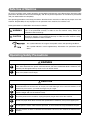
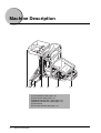
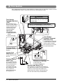
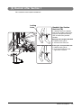
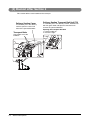
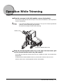
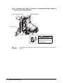
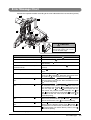
USRM1-9895-00
2011
Structure of the Users Guide
Chapter 1
Before You Begin
Chapter 2
Operating Procedures
Chapter 3
Troubleshooting
Chapter 4
Appendix
Read here first.
Important Information
• This manual is designed to help you to install, operate and maintain the trimmer. Please read and understand this manual, and keep it in a safe and convenient place.
• Do not operate the trimmer until you read and understand the instructions in this manual.
• Canon shall not be liable for incidental, consequential damages resulting from: improper or inadequate
maintenance by the customer, unauthorized modification or misuse, or operation outside of the environmental specifications for the product.
• Canon pursues a policy of continuing improvement in design and performance of the product. Therefore, the
product design and specifications are subject to change without prior notice and without legal obligation.
• All rights are reserved. No part of this manual may be photocopied, reproduced or translated to another language without the prior written consent of your local authorized dealer.
• This product applies to the CE Marking.
• This manual describes the operating procedures for the booklet trimmer-D1. For trimmer operations set from
the host machine (printer), see the operating manual of the host machine (printer.)
i
Safe Use of Machine
To use this machine safely, proper operation and periodical maintenance are indispensable. Read the safety
precautions described in this manual thoroughly, and do not perform operations or maintenance procedures
until you understand them completely.
The operating procedures and safety precautions described in this manual are valid only for proper use of this
machine. Responsibility for any improper use or operation of this machine, lies with the user.
Safety precautions are indicated in this manual as follows:
WARNING
Indicates a warning concerning operations that may lead to death or injury to persons if not performed correctly. In order to use the machine safely, always pay
attention to these warnings.
CAUTION
Indicates a caution concerning operations that may lead to injury to persons, or
damage to property if not performed correctly. In order to use the machine safely,
always pay attention to these cautions.
This symbol indicates the range of acceptable values and operating conditions.
This symbol indicates useful supplementary information for operational procedures.
Operating Safety Precautions
WARNING
When moving the machine, be sure to turn off all of the power switches for the connected equipment, then disconnect the power cord and contact your local authorized dealer. Otherwise, the
cord may be damaged and may result in a fire or electric shock.
Do not remove the safety covers or deactivate the sensor switches for the safety covers. Otherwise, it may lead to severe injury.
CAUTION
When removing jammed booklets from the trim section, take care not to touch the blade. Or when removing
jammed booklets from Infeed section, do not put your hands and fingers close to the belt. Otherwise, if the
belt drives by some chance, your hands and fingers may be caught.
This machine weighs about 152 kg (335 lb). When you operate the machine, consider the
machine weight and use the machine safely.
To cut the power on this machine, unplug the power plug on the back of the machine.
Do not use paper which does not meet the specifications. Otherwise, it may cause paper jams.
Do not open the covers while machine operation, or the machine will stop and booklets will jam.
Use this machine at office or commercial environment. Do not use this machine at industrial environment.
ii
Caution Label Locations
When removing jammed booklets
from the trim section, take care not
to touch the blade.
When removing jammed booklets
from Infeed section, do not put your
hands and fingers close to the belt.
Otherwise, if the belt drives by some
chance, your hands and fingers may
be caught.
FCC NOTICES
NOTICE
This equipment has been tested and found to comply with the limits for a Class A digital device, pursuant to
Part 15 of the FCC Rules. These limits are designed to provide reasonable protection against harmful interference when the equipment is operated in a commercial environment. This equipment generates, uses
and can radiate radio frequency energy and, if not installed and used in accordance with the instruction
manual, may cause harmful interference to radio communications. Operation of this equipment in a residential area is likely to cause harmful interference, in which case the user will be required to correct the
interference at this own expense.
FCC WARNING
Changes or modifications not expressly approved by the party responsible for compliance could
void the user's authority to operate the equipment.
iii
CONTENTS
Important Information ...............................................................................................................i
Safe Use of Machine ...............................................................................................................ii
Operating Safety Precautions ..................................................................................................ii
Caution Label Locations ......................................................................................................... iii
FCC NOTICES ....................................................................................................................... iii
Section 1
Before You Begin
Machine Description ............................................................................................................ 1-2
Section Descriptions ............................................................................................................ 1-3
[1] Infeed Section ........................................................................................................... 1-3
[2] Trim Section .............................................................................................................. 1-4
[3] Booklet Lifter Section 1 .............................................................................................. 1-5
[4] Booklet Lifter Section 2 .............................................................................................. 1-6
[5] Conveyor Section ...................................................................................................... 1-7
Section 2
Operating Procedures
Trimmer Setup ..................................................................................................................... 2-2
Operation While Trimming ................................................................................................... 2-3
Section 3
Troubleshooting
Error Messages ................................................................................................................... 3-2
Service Call Error ........................................................................................................... 3-2
Error Message Chart ...................................................................................................... 3-3
Clearing Paper Jams ........................................................................................................... 3-4
Section 4
Appendix
Specifications ...................................................................................................................... 4-2
Specifications ................................................................................................................. 4-2
Index .................................................................................................................................... 4-3
iv
Before You Begin
1
CHAPTER
Machine Description ............................................................................................................................ 1-2
Section Descriptions ............................................................................................................................ 1-3
[1] Infeed Section ............................................................................................................................ 1-3
[2] Trim Section............................................................................................................................... 1-4
[3] Booklet Lifter Section 1 .............................................................................................................. 1-5
[4] Booklet Lifter Section 2 .............................................................................................................. 1-6
[5] Conveyor Section....................................................................................................................... 1-7
1-1
Machine Description
[6]
[5]
[4]
[3]
[2]
[1] Infeed Section (See page 1-3.)
[2] Trim Section (See page 1-4.)
[3] Booklet Lifter Section 1 (See page 1-5.)
[4] Booklet Lifter Section 2 (See page 1-6.)
[5] Front Cover
[6] Conveyor Section (See page 1-7.)
1-2
Machine Description
[1]
Section Descriptions
[1] Infeed Section
Booklets delivered from the host machine are received here. The booklets are jogged, and then
transported to the trim section.
Once the trimmer is installed, you cannot touch this section. When booklet jams in this section,
pull out the trim unit and remove the jammed booklet from the space on the trim unit (See page
1-4.).
Top-bottom Guides
These guides jog the booklet.
Transport Hooks
These hooks push each booklet
into the trim section.
Transport Belts
These belts move the booklets.
Section Descriptions
1-3
[2] Trim Section
Each booklet delivered from the Infeed Section is trimmed along its fore-edge, and then moved
to the booklet lifter section. To pull out the trim unit, hold the green handle.
CAUTION
Trim Section
Transport Belt Unit
[TC4]
When booklets jam in
the trim section, hold the
handle with green label
and open this mechanism to remove the
jammed booklets.
Opening the
Transport Belt Unit
1. Hold and press the
handle.
2. Open to the right.
1
When removing jammed booklets from
the trim section, take care not to touch
the blade edge.
Removing Jammed Booklet in Infeed Section
1. Remove the jammed booklet from the space here.
Trim Section
Entrance Transport
Belt Unit [TC3]
2
If a booklets jam in the trim
section entrance, hold the
green handle and open
this mechanism to remove
the jammed booklets.
Transport Belts
These belts move the
booklets.
2
Handle [TC2]
Hold this green
handle and pull out the
trim unit.
Trimmer Booklet
Waste Tray
Trim is collected in this
tray. When it is full, the
host machine displays
an error message.
If trim drops off inside
the machine when this
tray is pulled out,
make sure to remove
the dropped trim.
1-4
Section Descriptions
1
Opening the Transport Belt Unit
1. Hold and press the handle.
2. Pull to the right.
3. Lift the mechanism up.
Manual Hand Wheel [TC1]
When booklets jam between the Infeed section and the trim section, turn this hand wheel
clockwise and transport the booklet completely to the trim section. Then pull out the
trim unit and remove the jammed booklet.
[3] Booklet Lifter Section 1
This section lifts each booklet and delivers.
Locking
Lever
Booklet Lifter Section
Belt Unit [TB]
If a booklets jam in the booklet
lifter section, hold the green locking lever and open this mechanism to remove the jammed
booklets.
Opening the Transport Belt Unit
1. Hold the locking lever.
2. Turn the lever to the left.
Closing the Transport Belt Unit
1. Hold the locking lever.
2. Push the mechanism to the
right until it is locked.
Section Descriptions
1-5
[4] Booklet Lifter Section 2
This section delivers each booklet to the conveyor.
Delivery Section Cover
If a booklets jam in the delivery
section, open this cover and
remove the jammed booklets.
Transport Belts
These belts move the
booklets.
1-6
Section Descriptions
Delivery Section Transport Belt Unit [TA]
If a booklets jam in the delivery section, hold the handle with green label and open this mechanism to
remove the jammed booklets.
Opening the Transport Belt Unit
1. Lift the handle up.
2. Pull to the right.
[5] Conveyor Section
The booklets delivered from the booklet lifter section are laid out on the conveyor.
Handle [TE]
Hold this handle and lift the roller unit when
removing the booklets on the conveyor.
Delivery
Transport
Rollers
Output booklets are
held by this roller.
The position of the
roller is set automatically to match the
booklet size.
Booklet Detect
Sensor
This sensor detects
the conveyor full with
stacked booklets.
Transport Belts
Delivery Tray *1
This belt moves while booklets are being
output, after booklets are ejected, and
transports them.
This tray holds the stacked
booklets. It is removable.
(When the tray is removed, the
conveyor full is not detected,
and the continuous operation is
possible.)
*1
Removing the delivery tray.
1. Loosen two locking knobs.
2. Lift the delivery tray up to remove.
3. Tighten two locking knobs.
Delivery Tray
Locking Knobs
Section Descriptions
1-7
1-8
Section Descriptions
Operating Procedures
2
CHAPTER
Trimmer Setup ..................................................................................................................................... 2-2
Operation While Trimming ................................................................................................................... 2-3
2-1
Trimmer Setup
1
Turn on the power switch on the saddle stitcher first, then turn on
the power switch on the host machine (printer).
Trimmer will also be powered on because it is connected to the saddle stitcher.
See the operation manual for the printer and set up the printer.
2-2
Trimmer Setup
Operation While Trimming
When the conveyor is full with booklets, remove the booklets.
If the machine stops because the conveyor is full, remove the booklets, and the operation
restarts automatically.
· If you remove booklets before the conveyor is full, you can increase production
efficiency, without interrupting the operation.
· Be careful not to drop the book while removing.
Delivery Tray
Trimmer Booklet Waste Tray
When the trimmer booklet waste tray is full, open the front cover, pull
out the trimmer booklet waste tray, and empty it.
If trim drops off inside the machine when this tray is pulled out, make sure to remove the
dropped trim.
To reposition the trimmer booklet waste tray, insert until it reaches to the rear end.
Close the front cover, and the operation restarts automatically.
Operation While Trimming
2-3
If a booklets jam, open the cover or mechanism shown below to
remove the jammed booklets.
Delivery Section Cover
Transport Belt Unit
Front Cover
Trim Unit
CAUTION
When removing jammed
booklets from the trim section, take care not to touch
the blade edge.
· If the booklets jam frequently, refer to page 3-4 for instructions on correcting the
problem.
2-4
Operation While Trimming
Troubleshooting
This section describes the cause and solution of the errors.
3
CHAPTER
Error Messages.................................................................................................................................... 3-2
Service Call Error............................................................................................................................ 3-2
Error Message Chart....................................................................................................................... 3-3
Clearing Paper Jams ........................................................................................................................... 3-4
3-1
Error Messages
When an error occurs and the machine does not work properly, “SERVICE CALL ERROR”
appears on the LCD of the host machine (printer). If “SERVICE CALL ERROR” appears, perform
as follows:
WARNING
Do not plug in or pull out the power plug with wet
hands. It may cause an electrical shock.
CAUTION
When you pull the power plug out, be sure to hold
the plug as you do so. If you pull it out by the power
cable, it may expose or cut the core wires and
cause a leak of electricity, which may result in fire or
electrical shock.
Service Call Error
When the SERVICE CALL ERROR appears on the LCD of the host machine, turn off the power
switch of the saddle stitcher and the printer. Wait about 10 seconds, and then turn on the power
switch again. If the SERVICE CALL ERROR is still shown on the LCD of the host machine, check
the following items, turn off the main power, and disconnect the power plug of the booklet trimmer-D1. Then contact your local authorized dealer.
- Product Name
- State of trouble
- Code number indicated on the touch panel display of the host machine (printer)
3-2
Error Messages
Error Message Chart
Perform the required remedies according to the error indicated on the host machine (printer).
E
2
B
A
C4
C3
D
1
C2
3
CAUTION
C1
When removing jammed booklets
from the trim section, take care not
to touch the blade edge.
Cause of Error
Remedy
The delivery section cover is open.
Close the delivery section cover 2 .
The front cover is open.
Close the front cover 1 .
The trim unit is not inserted correctly.
Hold the handle
end correctly.
The trimmer booklet waste tray is not
inserted correctly.
Insert the trimmer booklet waste tray 3 to the rear end
correctly.
The conveyor is full.*1
Lift the
veyor.
The trimmer booklet waste tray is full.
Open the front cover 1 , pull out the trimmer booklet
waste tray 3 , and empty it. Reposition the trimmer booklet waste tray 3 and close the front cover 1 .
C2 and insert the trim unit to the rear
E handle and remove the booklets from the con-
A booklet jam has occurred in
tion.
D sec-
Open the front cover 1 and remove the jammed booklet
from the space on the trim unit. Then close the front cover
1 to restart the printing.
A booklet jam has occurred in
tion.
C sec-
C1 manual hanOpen the front cover 1 and turn the
dle clockwise to transport the jammed booklet to the trim
unit completely, then hold the C2 handle to pull out the
C3 and
C4 transport belt unit,
trim unit. Open the
C3
and remove the jammed booklet. Reposition the
and C4 transport belt unit and hold the C2 handle to
reposition the trim unit. Then close the front cover 1 to
restart the printing.
A booklet jam has occurred in
tion.
B sec-
B transport belt unit.
Open the front cover 1 and the
Remove the jammed booklet, reposition the B transport
belt unit and the front cover 1 to restart the printing.
A booklet jam has occurred in
tion.
A sec-
Lift the E handle and remove the jammed booklet comA
pletely. Open the delivery section cover 2 and the
transport belt unit. Remove the jammed booklet, close the
A transport belt unit and the delivery section cover 2
to restart the printing.
Booklet waste exists at delivery section.
*1
If this error message appears when the conveyor is not full, trim may exists at the sensor.
Error Messages
3-3
Clearing Paper Jams
Jam in Conveyor Section
• Paper chip jams. (See procedure 1.)
• Transport belts are dirty. (See
procedure 2.)
Jam in Booklet Lifter Section 2
• Paper chip jams. (See procedure 1.)
• Transport belts are dirty. (See procedure 2.)
Jam in Booklet Lifter Section 1
• Paper chip jams. (See procedure 1.)
• Transport belts are dirty. (See procedure 2.)
Jam in Infeed Section
• Paper chip jams. (See procedure 1.)
• Transport belts are dirty. (See
procedure 2.)
Jam in Trim Section
• Paper chip jams. (See procedure 1.)
• Transport belts are dirty.
(See procedure 2.)
CAUTION
When removing jammed booklets
from the trim section, take care
not to touch the blade edge.
Procedure 1
Open the guide and check to see if there are any paper chips left on the booklet feed path. (See
page 3-3.)
Procedure 2
Transport belt cleaning is required. To clean the transport belt, contact your local authorized
dealer.
3-4
Clearing Paper Jams
Appendix
4
CHAPTER
Specifications ....................................................................................................................................... 4-2
Index .................................................................................................................................................... 4-3
4-1
Specifications
Specifications
Product Name
Booklet Trimmer-D1
Description of Product
Upper knife reciprocating fore-edge trimmer with delivery tray
Maximum Number of Sheets Trimmable
*1, *2
50 sheets (80 gsm),
48 sheets (80 gsm) + 2 sheets (300 gsm)
Possible Trimming Size*3
A3, B4, A4R, 13" x 19.2" (330.2mm x 487.7 mm), 12" x 18", 11" x
17", LGL, LTRR, 12.60" x 17.72" (320 mm x 450 mm [SRA3])
(Above sizes are native sheet sizes before half folded.)
Possible Trimming Width
Fore edge : 2 to 20 mm (0.08” to 0.78”)
Trimmer Booklet Waste Tray Capacity
Approximately 1,500 sheets of trimmed strip (width 20 mm
[0.78"], A4, 80 gsm)
Conveyor Capacity *4
30 booklets (40 sheets of A4 booklet, 80 gsm, 20mm [0.78”] of trimming width)
Machine Dimensions
1,575 (W) x 770 (D) x 1,040 (H) mm (62" x 30 3/8" x 41")
(With conveyor section and delivery tray)
Weight
Approximately 152 kg (335 lb)
Installation Space with Host Machine
Installation space differs depending on the connected host
machine. Refer to the "Machine Dimension" described on the
manual of the host machine, and this machine.
Voltage
From the Finisher
Power Consumption
300 W or less
Maximum Load Current
4A
Noise Level
70 dBA or less
Environmental
Temperature
in Use
Compliant with the specification of the host machine (printer)
Temperature
in Storage
-10 to 40°C (14 to 104°F)
Temperature
in Transportation
-10 to 50°C (14 to 122°F)
Humidity
Compliant with the specification of the host machine (printer)
Pressure
608 to 1,013 hPa
Contamination
Level
Pollution Degree 2 (Office environment)
*1 If the cover sheet is thinner than the other sheets in the booklet, the cover sheet may be scratched. It is
recommended to use a thicker sheet for the cover sheet.
*2 The maximum number of sheets trimmable can change depending on the connected host machine.
*3 The possible trimming size can change depending on the connected host machine.
*4 When the delivery tray is removed, the conveyor full condition is not detected, and the continuous operation is possible.
4-2
Specifications
Index
B
P
Booklet Lifter Section 1 ............................ 1-2, 1-5
Booklet Lifter Section 2 ............................ 1-2, 1-6
Booklet Lifter Section Belt Unit .......................1-5
Paper Jams ...................................................... 3-4
C
S
Service Call Error............................................. 3-2
Specifications ................................................... 4-2
Conveyor Section ..................................... 1-2, 1-7
T
D
Delivery Section Cover ....................................1-6
Delivery Section Transport Belt Unit...............1-6
Delivery Transport Rollers ...............................1-7
Delivery Tray ............................................ 1-7, 2-3
E
Error Message Chart........................................3-3
Error Messages ................................................3-2
Top-bottom Guide ............................................ 1-3
Transport Belt Unit ........................................... 2-4
Transport Belts........................... 1-3, 1-4, 1-6, 1-7
Transport Hooks .............................................. 1-3
Trim Section .............................................. 1-2, 1-4
Trim Section Entrance Transport Belt Unit .... 1-4
Trim Section Transport Belt Unit .................... 1-4
Trim Unit ........................................................... 2-4
Trimmer Booklet Waste Tray ................... 1-4, 2-3
Trimmer Setup ................................................. 2-2
F
Front Cover .......................................................1-2
H
Handle ....................................................... 1-4, 1-7
I
Infeed Section........................................... 1-2, 1-3
J
Jam in Booklet Lifter Section ...........................3-4
Jam in Infeed Section ......................................3-4
Jam in Trim Section .........................................3-4
L
Locking Lever ...................................................1-5
M
Manual Hand Wheel ........................................1-4
Index
4-3
4-4
Index
CANON INC.
30-2, Shimomaruko 3-chome, Ohta-ku, Tokyo 146-8501, Japan
CANON U.S.A., INC.
One Canon Plaza, Lake Success, NY 11042, U.S.A.
CANON CANADA INC.
6390 Dixie Road Mississauga, Ontario L5T 1P7, Canada
CANON EUROPA N.V.
Bovenkerkerweg 59-61 1185 XB Amstelveen, The Netherlands
(See http://www.canon-europe.com/ for details on your regional dealer)
CANON LATIN AMERICA, INC.
703 Waterford Way Suite 400 Miami, Florida 33126 U.S.A.
CANON AUSTRALIA PTY. LTD
1 Thomas Holt Drive, North Ryde, Sydney, N.S.W. 2113, Australia
CANON CHINA CO., LTD
15F Jinbao Building No.89 Jinbao Street, Dongcheng District, Beijing 100005, China
CANON SINGAPORE PTE. LTD.
1 HarbourFront Avenue #04-01 Keppel Bay Tower, Singapore 098632
CANON HONGKONG CO., LTD
19/F., The Metropolis Tower, 10 Metropolis Drive, Hunghom, Kowloon, Hong Kong
USRM2-0169-00
© CANON INC. 2011