1
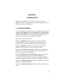
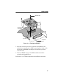
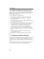
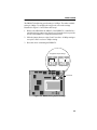
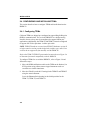
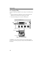
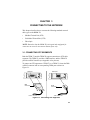
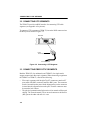
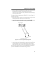
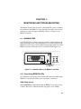
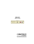
BRIM-T6
USER’S GUIDE
NOTICE
Cabletron Systems reserves the right to make changes in specifications and other
information contained in this document without prior notice. The reader should in all cases
consult Cabletron Systems to determine whether any such changes have been made.
The hardware, firmware, or software described in this manual is subject to change without
notice.
IN NO EVENT SHALL CABLETRON SYSTEMS BE LIABLE FOR ANY
INCIDENTAL, INDIRECT, SPECIAL, OR CONSEQUENTIAL DAMAGES
WHATSOEVER (INCLUDING BUT NOT LIMITED TO LOST PROFITS) ARISING
OUT OF OR RELATED TO THIS MANUAL OR THE INFORMATION CONTAINED
IN IT, EVEN IF CABLETRON SYSTEMS HAS BEEN ADVISED OF, KNOWN, OR
SHOULD HAVE KNOWN, THE POSSIBILITY OF SUCH DAMAGES.
© Copyright 1995 by: Cabletron Systems, Inc.
P.O. Box 5005, Rochester, NH 03866-5005
All Rights Reserved
Printed in the United States of America
Order Number: 9031288 September 1995
LANVIEW, Remote LANVIEW, SPECTRUM, BRIM, TPIM-T1, TPIM-T2,
TPIM-T4, TPIM-F2, TPIM-F3, and MicroMMAC are trademarks of Cabletron
Systems, Inc.
CompuServe is a registered trademark of CompuServe, Inc.
Intel is a registered trademark of the Intel Corporation.
Printed on
recycled paper.
i
NOTICE
FCC NOTICE
This device complies with Part 15 of the FCC rules. Operation is subject to the following
two conditions: (1) this device may not cause harmful interference, and (2) this device must
accept any interference received, including interference that may cause undesired
operation.
NOTE: This equipment has been tested and found to comply with the limits for a Class A
digital device, pursuant to Part 15 of the FCC rules. These limits are designed to provide
reasonable protection against harmful interference when the equipment is operated in a
commercial environment. This equipment uses, generates, and can radiate radio frequency
energy and if not installed in accordance with the operator’s manual, may cause harmful
interference to radio communications. Operation of this equipment in a residential area is
likely to cause interference in which case the user will be required to correct the
interference at his own expense.
WARNING: Changes or modifications made to this device which are not expressly
approved by the party responsible for compliance could void the user’s authority to operate
the equipment.
DOC NOTICE
This digital apparatus does not exceed the Class A limits for radio noise emissions from
digital apparatus set out in the Radio Interference Regulations of the Canadian Department
of Communications.
Le présent appareil numérique n’émet pas de bruits radioélectriques dépassant les limites
applicables aux appareils numériques de la class A prescrites dans le Règlement sur le
brouillage radioélectrique édicté par le ministère des Communications du Canada.
VCCI NOTICE
This equipment is in the 1st Class Category (information equipment to be used in
commercial and/or industrial areas) and conforms to the standards set by the Voluntary
Control Council for Interference by Information Technology Equipment (VCCI) aimed at
preventing radio interference in commercial and/or industrial areas.
Consequently, when used in a residential area or in an adjacent area thereto, radio
interference may be caused to radios and TV receivers, etc.
Read the instructions for correct handling.
ii
NOTICE
PROGRAM LICENSE AGREEMENT
IMPORTANT: Before utilizing this product, carefully read this License Agreement.
This document is an agreement between you, the end user, and Cabletron Systems, Inc.
(“Cabletron”) that sets forth your rights and obligations with respect to the Cabletron
software program (the “Program”) contained in this package. The Program may be
contained in firmware, chips or other media. BY UTILIZING THE ENCLOSED
PRODUCT, YOU ARE AGREEING TO BECOME BOUND BY THE TERMS OF THIS
AGREEMENT, WHICH INCLUDES THE LICENSE AND THE LIMITATION OF
WARRANTY AND DISCLAIMER OF LIABILITY. IF YOU DO NOT AGREE TO THE
TERMS OF THIS AGREEMENT, PROMPTLY RETURN THE UNUSED PRODUCT TO
THE PLACE OF PURCHASE FOR A FULL REFUND.
CABLETRON SOFTWARE PROGRAM LICENSE
1.
LICENSE. You have the right to use only the one (1) copy of the Program provided in
this package subject to the terms and conditions of this License Agreement.
You may not copy, reproduce or transmit any part of the Program except as permitted
by the Copyright Act of the United States or as authorized in writing by Cabletron.
2.
OTHER RESTRICTIONS. You may not reverse engineer, decompile, or disassemble
the Program.
3.
APPLICABLE LAW. This License Agreement shall be interpreted and governed
under the laws and in the state and federal courts of New Hampshire. You accept the
personal jurisdiction and venue of the New Hampshire courts.
iii
NOTICE
EXCLUSION OF WARRANTY & DISCLAIMER OF
LIABILITY
1.
EXCLUSION OF WARRANTY. Except as may be specifically provided by Cabletron
in writing, Cabletron makes no warranty, expressed or implied, concerning the
Program (including Its documentation and media).
CABLETRON DISCLAIMS ALL WARRANTIES, OTHER THAN THOSE
SUPPLIED TO YOU BY CABLETRON IN WRITING, EITHER EXPRESS OR
IMPLIED, INCLUDING BUT NOT LIMITED TO IMPLIED WARRANTIES OF
MERCHANTABLITY AND FITNESS FOR A PARTICULAR PURPOSE, WITH
RESPECT TO THE PROGRAM, THE ACCOMPANYING WRITTEN
MATERIALS, AND ANY ACCOMPANYING HARDWARE.
2.
NO LIABILITY FOR CONSEQUENTIAL DAMAGES. IN NO EVENT SHALL
CABLETRON OR ITS SUPPLIERS BE LIABLE FOR ANY DAMAGES
WHATSOEVER (INCLUDING, WITHOUT LIMITATION, DAMAGES FOR LOSS
OF BUSINESS, PROFITS, BUSINESS INTERRUPTION, LOSS OF BUSINESS
INFORMATION, SPECIAL, INCIDENTAL, CONSEQUENTIAL, OR RELIANCE
DAMAGES, OR OTHER LOSS) ARISING OUT OF THE USE OR INABILITY TO
USE THIS CABLETRON PRODUCT, EVEN IF CABLETRON HAS BEEN
ADVISED OF THE POSSIBILITY OF SUCH DAMAGES. BECAUSE SOME
STATES DO NOT ALLOW THE EXCLUSION OR LIMITATION OF LIABILITY
FOR CONSEQUENTIAL OR INCIDENTAL DAMAGES, OR ON THE
DURATION OR LIMITATION OF IMPLIED WARRANTEES IN SOME
INSTANCES THE ABOVE LIMITATIONS AND EXCLUSIONS MAY NOT APPLY
TO YOU.
UNITED STATES GOVERNMENT RESTRICTED
RIGHTS
The enclosed product (a) was developed solely at private expense; (b) contains “restricted
computer software” submitted with restricted rights in accordance with Section 52227-19
(a) through (d) of the Commercial Computer Software - Restricted Rights Clause and its
successors, and (c) in all respects is proprietary data belonging to Cabletron and/or its
suppliers.
For Department of Defense units, the product is licensed with “Restricted Rights” as
defined in the DoD Supplement to the Federal Acquisition Regulations, Section
52.227-7013 (c) (1) (ii) and its successors, and use, duplication, disclosure by the
Government is subject to restrictions as set forth in subparagraph (c) (1) (ii) of the Rights
in Technical Data and Computer Software clause at 252.227-7013. Cabletron Systems,
Inc., 35 Industrial Way, Rochester, New Hampshire 03867
iv
CONTENTS
CHAPTER 1
1.1
1.2
1.3
1.4
1.5
USING THIS MANUAL. . . . . . . . . . . . . . . . . . . . . . . . . . . . 1-1
INTRODUCING THE BRIM-T6 . . . . . . . . . . . . . . . . . . . . . 1-2
BRIM SPECIFICATIONS . . . . . . . . . . . . . . . . . . . . . . . . . . 1-4
RELATED DOCUMENTATION. . . . . . . . . . . . . . . . . . . . . . 1-4
GETTING HELP. . . . . . . . . . . . . . . . . . . . . . . . . . . . . . . . . 1-5
CHAPTER 2
2.1
2.2
2.3
2.4
4.2
CONNECTING TO THE NETWORK
CONNECTING STP SEGMENTS . . . . . . . . . . . . . . . . . . . 3-1
CONNECTING UTP SEGMENTS . . . . . . . . . . . . . . . . . . . 3-2
CONNECTING FIBER OPTIC SEGMENTS . . . . . . . . . . . 3-2
CHAPTER 4
4.1
INSTALLATION
UNPACKING THE BRIM-T6. . . . . . . . . . . . . . . . . . . . . . . . 2-1
INSTALLING THE BRIM-T6 . . . . . . . . . . . . . . . . . . . . . . . . 2-1
2.2.1 Installing the BRIM-T6 into a MIM . . . . . . . . . . . . . 2-2
2.2.2 Installing the BRIM-T6 into a Standalone Device. . 2-4
CONFIGURING THE BRIM-T6 RING SPEED. . . . . . . . . . 2-4
CONFIGURING AND INSTALLING TPIMs . . . . . . . . . . . . 2-6
2.4.1 Configuring TPIMs . . . . . . . . . . . . . . . . . . . . . . . . . 2-6
2.4.2 Installing TPIMs . . . . . . . . . . . . . . . . . . . . . . . . . . . 2-8
CHAPTER 3
3.1
3.2
3.3
INTRODUCTION
MONITORING AND TROUBLESHOOTING
LANVIEW LEDS . . . . . . . . . . . . . . . . . . . . . . . . . . . . . . . . 4-1
4.1.1 Describing BRIM-T6 LEDs . . . . . . . . . . . . . . . . . . . 4-1
CHECKING THE CONNECTION. . . . . . . . . . . . . . . . . . . . 4-3
APPENDIX A
TPIM SPECIFICATIONS
A.1 TWISTED PAIR TPIM PINOUTS: STATION MODE . . . . . .A-1
A.2 FIBER OPTIC TPIM SPECIFICATIONS . . . . . . . . . . . . . .A-1
v
CONTENTS
APPENDIX B
MEDIA SPECIFICATIONS AND
REQUIREMENTS
B.1 FIBER OPTIC . . . . . . . . . . . . . . . . . . . . . . . . . . . . . . . . . .B-1
B.2 SHIELDED TWISTED PAIR (STP) . . . . . . . . . . . . . . . . . .B-2
B.3 UNSHIELDED TWISTED PAIR (UTP) . . . . . . . . . . . . . . . .B-3
vi
CHAPTER 1
INTRODUCTION
Welcome to the BRIM-T6 USER’S GUIDE. This manual describes
BRIM-T6 features, installation instructions, and operating procedures. It is
intended for all users of the BRIM-T6.
1.1 USING THIS MANUAL
If you are unfamiliar with Cabletron Systems’ networking products, please
read this manual completely to gain an understanding of the features and
capabilities of the BRIM-T6. Also, you should have a general knowledge
of Token Ring (IEEE 802.5) data communications networks and their
physical layer components before operating the BRIM-T6.
This manual is organized as follows:
Chapter 1, Introduction, outlines the contents of this manual and
discusses BRIM-T6 features, capabilities, and specifications. It also
describes how to get technical help and lists related documentation.
Chapter 2, Installation, describes how to configure and install the
BRIM-T6 and Token Ring Port Interface Modules (TPIMs).
Chapter 3, Connecting to the Network, describes how to establish the
physical link to a Local Area Network (LAN) by connecting standard
network cable segments to the BRIM-T6.
Chapter 4, Monitoring and Troubleshooting, describes how to use the
LANVIEW LEDs diagnostic system to monitor the BRIM-T6’s
operational status. It also describes procedures for resolving problems
encountered establishing a link to a network via the BRIM-T6 interface.
Appendix A, TPIM Specifications, describes specifications for Cabletron
Systems’ series of attachable TPIMs.
Appendix B, Media Specifications, describes specifications for network
media.
1-1
INTRODUCTION
1.2 INTRODUCING THE BRIM-T6
The BRIM-T6 (see Figure 1-1) is a SNMP-manageable daughterboard that
provides a bridging and routing interface for a variety of Cabletron
Systems’ Intel i960-based intelligent Token Ring and Ethernet host
devices (for example, the MicroMMAC-T concentrator and the EMM-E6
management module).
BRIM T6
16Mb XMT
STB RCV
Figure 1-1. BRIM-T6
NOTE: Contact your Cabletron Representative for up-to-date information
about products that support the BRIM-T6.
Media Flexibility
Used in conjunction with Cabletron Systems’ series of hot swappable
TPIMs, the BRIM-T6 can be configured for connection to all standard
network media. See Section 2.4 for instructions on how to configure and
install TPIMs. Table 1-1 lists TPIMs and their corresponding media and
connector types.
Table 1-1. TPIMs and Corresponding Media
1-2
TPIM
Corresponding Media
Connector
TPIM-T1
Shielded Twisted Pair
DB9
TPIM-T2
Unshielded Twisted Pair
RJ45
TPIM-T4
Shielded Twisted Pair
RJ45
TPIM-F2
Multimode Fiber Optic
ST
TPIM-F3
Single-mode Fiber Optic
ST
INTRODUCTION
Jumper Selectable Ring Speed
The BRIM-T6 has a ring speed selection jumper on its component board
that you can use to select operating ring speeds of either 4 or 16 megabits
per second (4 or 16 Mbps). See Section 2.3 for instructions on setting the
ring speed for the BRIM-T6.
Bridge/Routing Protocols
The BRIM-T6 provides Source Routing Transparent (SRT) bridging
between any of the channels or ports in its host MIM or hub and the Token
Ring. BRIM-T6 routing is determined by the routing protocols supported
by the firmware of the host device.
Spanning Tree Algorithm (STA) Compliance
The BRIM-T6 operates in compliance with the functional specifications of
the 802.1d STA, which is included in the firmware of the host device in
which the BRIM-T6 is installed. The STA is used to manage primary and
backup bridges and to maintain the reliability of the multi-bridged
internetwork by detecting and preventing potential data loops.
BRIM-T6 Management
The host device in which the BRIM-T6 is installed provides Local
Management (LM) applications for administering BRIM-T6
bridge/routing functions. The operation of the BRIM-T6 can also be
managed by remote SNMP applications such as Remote LANVIEW and
SPECTRUM. See the documentation included with the host device or
remote management application for information on how to administer
bridge/routing functions.
LANVIEW LEDs
The LANVIEW LEDs on the front panel of the BRIM-T6, together with
the LED on an installed TPIM, provide an at-a-glance means of monitoring
the operational status of the BRIM-T6. LEDs indicate, for example,
network connection status, data transmission activity, and ring speed
operation. See Chapter 4 for more information about LEDs.
1-3
INTRODUCTION
1.3 BRIM SPECIFICATIONS
Environment
Storage temperature:
- 30° to 90° C
Operating temperature:
5° to 40°C
Operating humidity:
5% to 95% non-condensing
Safety
This unit meets the safety requirements of UL 1950 (without D3
deviations), CSA C22.2 No. 950, and EN60950.
EMI
This unit meets the EMI requirements of FCC Part 15 Class A, EN55022
Class A and VCCI Class I.
EMC
This unit meets the EMC requirements of EN 50082-1 including: IEC
801-2 (ESD) levels 1 through 4, IEC 801-3 (Radiated Susceptibility)
levels 1 through 4, and IEC 801-4 (EFT/B) levels 1 through 4.
NOTE: It is the network system vendor’s responsibility to ensure that the
total network system, including the BRIM-T6, meets allowed limits of
conducted and radiated emissions.
1.4 RELATED DOCUMENTATION
The following documents provide supplementary information related to
the procedures and technical data in this manual.
Cabletron Documentation
Cabletron Systems’ EMM-E6 User’s Guide
Cabletron Systems’ MicroMMAC-E/MicroMMAC-T User’s Guides
Cabletron Systems’ ESXMIM User’s Guide
Cabletron Systems’ Router Services Manuals
Cabletron Systems’ Guide to Local Area Networking
1-4
INTRODUCTION
Networking Publications
The Simple Book, An Introduction to Management of TCP/IP-based
Internets, Marshall T. Rose, Prentice-Hall, Inc., 1991
Local Area Networks, Token Ring Access Method, IEEE Standard 802.5
(1989)
1.5 GETTING HELP
If you need help using the BRIM-T6 or have any questions, comments, or
suggestions concerning this manual, please contact Cabletron Systems
Technical Support Department:
By telephone:
(603) 332-9400
Monday-Friday; 8am - 8pm EST
By CompuServe®:
GO CTRON from any ! prompt
By Internet mail:
[email protected]
By Fax:
(603) 337-7055
By BBS:
(603) 337-3750
By mail:
Cabletron Systems, Inc.
P.O. Box 5005
Rochester, NH 03866-5005
1-5
INTRODUCTION
1-6
CHAPTER 2
INSTALLATION
This chapter describes how to unpack, configure, and install the BRIM-T6.
Because the operation of a BRIM-T6 requires a properly attached and
configured Token Ring Port Interface Module (TPIM), this chapter also
includes TPIM configuration and installation instructions.
CAUTION: Observe all precautions against electrostatic discharge when
handling the BRIM-T6, TPIMs, and other network devices. Electrostatic
discharge can damage a device’s processing components. Always wear a
properly grounded anti-static wrist strap when handling network devices.
Cabletron Systems includes an anti-static wrist strap and instructions with
all hardware devices.
2.1 UNPACKING THE BRIM-T6
1. Carefully remove the BRIM-T6 from the shipping box and leave it in
its non-conductive bag until ready for inspection and installation.
2. Attach the wrist strap provided with the BRIM-T6 to your wrist and to
a proper ground.
3. Inspect the BRIM-T6 after removing it from the bag. If there is any
damage, notify Cabletron Systems Technical Support Department (see
Section 1.5).
2.2 INSTALLING THE BRIM-T6
This section describes how to install the BRIM-T6 into MIMs and
standalone devices. You should have the following items:
•
Anti-static wrist strap
•
Two coverplate screws and two standoff, or support post, screws
included with the host device
•
#2 Phillips screwdriver
2-1
INSTALLATION
2.2.1 Installing the BRIM-T6 into a MIM
To install the BRIM-T6 into a Media Interface Module (MIM), refer to
Figure 2-1 and Figure 2-2 and follow these steps:
1. Disconnect all cables from the MIM as necessary. Note all prior
cable-to-port connections to ensure proper reconnection.
2. Remove the MIM from the MMAC and place it on its side with its
board components facing up.
3. Remove the BRIM receptacle coverplate from the MIM and the screws
from the standoffs as shown in Figure 2-1.
Standoff
Coverplate
Figure 2-1. Removing the Coverplate and the Standoff Screws
4. Place the BRIM behind the BRIM receptacle panel on the MIM,
aligning the screw holes on the BRIM with their corresponding screw
holes on the BRIM receptacle panel and on the standoffs as shown in
Figure 2-2.
2-2
INSTALLATION
Standoff screw
BRIM
T6
MT
bX
16M
STB
RCV
Connector pins
under BRIM
Connector
Coverplate
screw
Figure 2-2. Installing the BRIM-T6
5. Insert the connector pins on the underside of the BRIM into the
motherboard connector on the MIM by pressing down firmly on the
rear section of the BRIM until the pins slide all the way into the
connector holes.
6. Fasten the BRIM securely to the MIM motherboard with the
coverplate and standoff screws.
See Section 2.4 for TPIM configuration and installation instructions.
2-3
INSTALLATION
2.2.2 Installing the BRIM-T6 into a Standalone Device
Standalone devices have the same physical setup for BRIM installation as
MIMs. So you can refer to Figure 2-1 and Figure 2-2 when installing a
BRIM-T6 into a standalone device.
To install a BRIM into a standalone device:
1. Power off the device and remove its chassis cover. Refer to the
documentation included with the host device for instructions on
removing the chassis cover.
2. Remove the BRIM receptacle coverplate and the standoff screws from
the standoffs as shown in Figure 2-1.
3. Place the BRIM behind the receptacle panel, aligning the screw holes
on the BRIM with their corresponding screw holes on the BRIM
receptacle panel and on the standoffs as shown in Figure 2-2.
4. Insert the connector pins on the underside of the BRIM into the
motherboard connector in the device. Press down firmly on the rear
section of the BRIM until the pins slide all the way into the connector
holes.
5. Fasten the BRIM securely to the device motherboard with the
coverplate and standoff screws.
6. Reinstall the device chassis cover and then power on the device.
2.3 CONFIGURING THE BRIM-T6 RING SPEED
You must configure the BRIM-T6 ring speed to match the ring speed of the
Token Ring to which it is physically linked. The BRIM-T6 ring speed
setting does not, however, have to match the ring speed setting of its host
device.
Also, you must reset the host device containing the BRIM-T6 after you
change the BRIM-T6’s ring speed for the change to take effect.
2-4
INSTALLATION
The BRIM-T6 default ring speed setting is 16 Mbps. The other available
setting is 4 Mbps. To configure the ring speed, refer to the settings
illustrated in Figure 2-3 and follow these steps:
1. Remove the MIM from the MMAC; if the BRIM-T6 is installed in a
standalone device, remove the chassis cover from the device to provide
access to the BRIM-T6’s component board surface.
2. Slide the jumper down over pins 2 and 3 to select a 16 Mbps setting or
over pins 1 and 2 to select a 4 Mbps setting.
3. Reset the device containing the BRIM-T6.
Ring Speed Jumper Settings
J3
1
2
J3
3
1
2
3
16M
SPD
4M
16M
SPD
4M
4 Mbps Setting
16 Mbps Setting
J3
Front Panel
16M
SPD
4M
Figure 2-3. BRIM-T6 Ring Speed Settings
2-5
INSTALLATION
2.4 CONFIGURING AND INSTALLING TPIMs
This section describes how to configure TPIMs and install them into the
BRIM-T6.
2.4.1 Configuring TPIMs
Cabletron TPIMs are shipped pre-configured to support Ring In/Ring Out
(RI/RO) communications. For use in the BRIM-T6 as a bridge/routing
interface, however, they must be reconfigured to support Station port
applications. Additionally, the TPIM-F2 and TPIM-F3 must be configured
to support 802.5J lobe operations via fiber optic cable.
NOTE: TPIM-F2 hardware version 04 and TPIM-F3 hardware version 02
or higher must be used to provide bridge links via fiber optic cable. Prior
versions do not support this functionality with the BRIM-T6.
Refer to the TPIM-F2/TPIM-F3 part number location shown in Figure 2-4
to determine functional compatibility with the BRIM-T6.
To configure TPIMs for use with the BRIM-T6, refer to Figure 2-4 and
follow these steps:
1. Move the RI/RO and Station switch on the TPIMs to the Station (S or
STN) position using a blunt, narrow-tipped instrument such as a
screwdriver or similar instrument.
2. Move the Fiber Key to the 802.5 setting for the TPIM-F2 and TPIM-F3
using the same instrument.
Leave the Phantom Switch setting in the default position for the
TPIM-T1, TPIM-T2, and TPIM-T4.
2-6
INSTALLATION
Top View
(See Below For Settings)
P
H
A
N
T
O
M
1
8
0
2
.
5
S
RI/RO
TPIM-T1/TPIM-T2/TPIM-T4
Ctron
S
T
N
RI/RO
PN . . . . .-0X REV
0
Part
Number
TPIM-F2/TPIM-F3
Phantom Switch Settings
1 = Cabletron Device (Default)
0 = Non-Cabletron Device
Fiber Key Settings
Ctron = Cabletron Device
802.5 = BRIM-T6 Functional
RI/RO-STN Switch Settings
RI/RO = Ring In/Ring Out (Default)
S = Station (BRIM-T6 Functional)
RI/RO-STN Switch Settings
RI/RO = Ring In Ring Out (Default)
STN = Station (BRIM-T6 Functional)
Figure 2-4. TPIM Configuration for Station Applications
NOTE: If the switch locations on a TPIM do not match the example
locations illustrated in Figure 2-4, refer to the TPIM Reference Card
included with the TPIM. The TPIM Reference Card outlines switch
locations and settings. For additional help, call Cabletron Systems
Technical Support Department (see Section 1.5).
2-7
INSTALLATION
2.4.2 Installing TPIMs
To install a TPIM into the BRIM-T6, refer to Figure 2-5 and follow these
steps:
1. Slide the TPIM into the TPIM slots until the connector pins in the
BRIM are fully inserted into the connector on the TPIM.
2. Fasten the mounting screw to secure the TPIM in place.
BRIM T6
TPIM
Slot
16Mb XMT
STB RCV
STACK2
STACK3
STACK4
STACK5
Connector
Mounting Screw
Figure 2-5. Installing a TPIM
The BRIM-T6 is now ready for operation. The next chapter describes
procedures for connecting a properly configured and installed BRIM-T6 to
the network.
2-8
CHAPTER 3
CONNECTING TO THE NETWORK
This chapter describes how to connect the following standard network
cable types to the BRIM-T6:
•
Shielded Twisted Pair (STP)
•
Unshielded Twisted Pair (UTP)
•
Fiber Optic
NOTE: Remember that the BRIM-T6 is designed and configured for
connection to network concentrator Station ports only.
3.1 CONNECTING STP SEGMENTS
Both the TPIM-T1 and the TPIM-T4 support connection to STP cable
segments. The TPIM-T1 provides a DB9 interface, and the TPIM-T4
provides an RJ45 interface (see Appendix A for pinouts).
To connect an STP segment to a TPIM-T1 or a TPIM-T4, insert the DB9
or RJ45 connector into its corresponding TPIM port as shown in
Figure 3-1.
DB9 Port
RJ45 Port
DB9
Connector
RJ45
Connector
TPIM-T1 Connection
TPIM-T4 Connection
Figure 3-1. Connecting STP Segments
3-1
CONNECTING TO THE NETWORK
3.2 CONNECTING UTP SEGMENTS
The TPIM-T2 provides an RJ45 interface for connecting UTP cable
segments (see Appendix A for pinouts).
To connect a UTP segment to a TPIM-T2, insert the RJ45 connector into
the RJ45 port as shown in Figure 3-2.
RJ45 Port
RJ45
Connector
TPIM-T2 Connection
Figure 3-2. Connecting a UTP Segment
3.3 CONNECTING FIBER OPTIC SEGMENTS
Both the TPIM -F2 (for multimode) and TPIM-F3 (for single-mode)
support connection to fiber optic segments. When connecting a segment to
the TPIM-F2 or TPIM-F3, consider the following:
•
Fiber optic segments with Straight Tip (ST) connectors attach to ST
ports much like BNC connectors attach to BNC ports. The connector
must be inserted into the port with the alignment key on the connector
inserted into the alignment slot on the port. Then the connector must
be turned to lock it down.
•
The physical communication link consists of two strands of fiber optic
cabling. The Transmit strand (TX) at one end connects to the Receive
(RX) port at the other end and vice versa.
3-2
CONNECTING TO THE NETWORK
•
Dust, dirt, and other contaminants on the ends of the connectors create
data transmission problems. Avoid touching the ends of the
connectors. If the ends become dirty, clean them with alcohol using a
soft, clean, lint-free cloth.
To connect a fiber optic segment to the TPIM-F2 /-F3, refer to Figure 3-3
and follow these steps:
1. Remove the protective plastic covers from the fiber optic ports on the
module and from the connectors on each fiber strand.
2. Attach a fiber strand to the module’s receive port (labeled RX) and the
other fiber strand to the module’s transmit port (labeled TX).
RX Port TX Port
Fiber strands
To RX Port
To TX Port
TPIM-F2/TPIM-F3 Connection
Figure 3-3. Connecting Fiber Optic Segments
3. Attach the other end of the strand that is connected to the host RX port
to the destination device’s TX port and attach the other end of the
strand connected to host TX port to the destination device’s RX port.
The next chapter describes how to use LANVIEW LEDs to monitor the
operation of the BRIM-T6 and troubleshooting procedures.
3-3
CONNECTING TO THE NETWORK
3-4
CHAPTER 4
MONITORING AND TROUBLESHOOTING
This chapter describes how to use the LANVIEW LED system to monitor
the operation of the BRIM-T6. It also describes procedures for resolving
problems you may encounter establishing a link to a network via the
BRIM-T6 interface.
4.1 LANVIEW LEDS
LANVIEW LEDs are Cabletron Systems’ built-in, visual diagnostic and
status monitoring system. The comprehensive LANVIEW system for the
BRIM-T6 consists of four LEDs (Light Emitting Diodes) on the face of the
BRIM-T6 and one LED on the face of its attached TPIM (Figure 4-1).
16Mb XMT
STB RCV
LANVIEW LEDs
Figure 4-1. LANVIEW LEDs on the BRIM-T6 and TPIM
4.1.1 Describing BRIM-T6 LEDs
The information conveyed by each LED about the operational status of the
BRIM-T6 is described as follows (also see Table 4-1 summary):
16Mb (Ring Speed)
When solid Yellow, 16Mb indicates that the BRIM-T6 ring speed is set to
16 Mbps. When off, it indicates that the ring speed is set to 4 Mbps.
4-1
MONITORING AND TROUBLESHOOTING
XMT (Transmit)
When flashing Green, XMT indicates that the BRIM-T6 is transmitting
traffic to the Token Ring network. When solid Red, XMT indicates that the
BRIM-T6 is disabled.
When blinking Red, XMT indicates a speed fault condition, typically
caused by a mismatch in ring speeds between the BRIM-T6 and the ring
occupied by the device to which it is linked. See Section 2.3 for
information about setting the correct ring speed.
RCV (Receive)
When solid Green, RCV indicates that the BRIM-T6 is currently enabled
to receive Token Ring traffic, and when flashing Yellow, it indicates that it
is currently receiving Token Ring traffic. When solid Red, RCV indicates
that the BRIM-T6 is disabled by the host device.
STB (Standby)
When solid Yellow, STB indicates a standby condition: the BRIM-T6 is
not ready or able to transmit data to the ring. Standby conditions are
caused, typically, when the host device is initializing or when a TPIM is
not attached to the BRIM-T6.
LNK (Media Link OK) on attached TPIM
When solid Green, LNK indicates that a connection exists between the
BRIM-T6 and a node at the other end of the media segment. When off, (or
also when Red on the TPIM-T1/-T2/-T4) this LED indicates either that the
BRIM-T6 is not connected to another device or that the port is not
receiving a signal.
4-2
MONITORING AND TROUBLESHOOTING
Table 4-1. LED Specifications Summary
LED
Status
Description
16Mb (Ring Speed)
Solid Yellow
Off
16 Mbps
4 Mbps
XMT (Transmit)
Flashing Green
Solid Red
Blinking Red
Transmitting Traffic
Disabled
Speed Fault Error
RCV (Receive)
Solid Green
Flashing Yellow
Solid Red
Enabled
Receiving Traffic
Disabled
STB (Standby)
Solid Yellow
Standby
LNK (Link)
Solid Green
Media Link OK
4.2 CHECKING THE CONNECTION
This section provides a checklist for troubleshooting network connection
problems.
The LNK LED on the TPIM lights green when there is an established link
between the BRIM-T6 and the device at the other end of the media
connection. If, however, the LNK LED lights red or is not lighted, a link
has not been established. To resolve the problem, try the following
procedures:
•
Check that the host device and the device at the other end of the
segment have power.
•
Check that the TPIM is securely installed in the BRIM-T6 and that the
BRIM-T6 is securely installed in the host device.
•
Check for correct connector-to-port attachments at the BRIM-T6 and
the destination device.
•
Inspect the cabling system (cable and connectors) for damage and
replace damaged components.
4-3
MONITORING AND TROUBLESHOOTING
•
Verify that STP and UTP connectors (DB9 and RJ45) are pinned
properly. For fiber, verify that the receive-to-transmit connection of
strands between devices is correct.
•
Check that the connection meets the dB loss limit and media
specifications outlined in Appendix B.
•
Check that the BRIM-T6 port is enabled through Local Management.
Contact Cabletron Systems Technical Support if you still cannot establish
a network link.
4-4
APPENDIX A
TPIM SPECIFICATIONS
A.1 TWISTED PAIR TPIM PINOUTS: STATION MODE
Figure A-1 illustrates pinouts for TPIMs that support twisted pair cable
(STP and UTP) and that are also configured to support Station
applications.
.
TPIM-T1
5
4
9
3
8
2
7
1
TPIM-T2/TPIM-4
12345678
6
1 Receive +
2 Ground
3 +5V at 250mA
4 Ground
5 Transmit 6 Receive 7 Ground
8 Ground
9 Transmit +
1 Not Used
2 Not Used
3 Transmit 4 Receive +
5 Receive 6 Transmit +
7 Ground
8 Not Used
Figure A-1. TPIM-T1/T2/T4 Pinouts for Station Mode.
A.2 FIBER OPTIC TPIM SPECIFICATIONS
The TPIM-F2 supports Multimode fiber optic cabling, and the TPIM-F3
supports Single-mode fiber optic cabling.
Table A-1 lists TPIM-F2 specifications, and Table A-2 lists TPIM-F3
specifications.
A-1
TPIM SPECIFICATIONS
Table A-1. TPIM-F2 Performance Specifications
Typical
Value
Worst Case
Worst Case
Budget
Typical
Budget
Receive
Sensitivity
-30.5 dBm
-28.0 dBm
—
—
Peak Input
Power
-7.6 dBm
-8.2 dBm
—
—
Parameter
Transmitter Power:
50/125 µm
-13.0 dBm
-15.0 dBm
13.0 dB
17.5 dB
62.5/125 µm
-10.0 dBm
-12.0 dBm
16.0 dB
20.5 dB
100/140 µm
-7.0 dBm
-9.0 dBm
19.0 dB
23.5 dB
Bit Error Rate: Better than 10-10
The transmitter power and receive sensitivity levels given in Table A-1 and
Table A-2 are Peak Power Levels after optical overshoot. A Peak Power
Meter must be used to correctly compare the given values to those
measured on any particular port.
Table A-2. TPIM-F3 Specifications
Parameter
Typical
Minimum
Maximum
Transmitter
Peak Wave Length
1300 nm
1270 nm
1330 nm
Spectral Width
60 nm
–
100 nm
Rise Time
3.0 nsec
2.7 nsec
5.0 nsec
Fall Time
2.5 nsec
2.2 nsec
5.0 nsec
Duty Cycle
50.1%
49.6%
50.7%
Bit Error Rate: Better than 10-10
A-2
APPENDIX B
MEDIA SPECIFICATIONS AND REQUIREMENTS
This Appendix provides information about cabling media (Fiber, STP,
UTP) used with the BRIM-T6.
B.1 FIBER OPTIC
Table B-1 defines total signal attenuation tolerances for both single-mode
and multimode fiber cabling. Both types of cabling have a typical constant
attenuation rate per km of fiber cable, and each connector on the cable
system contributes significant additional attenuation. Maximum drive
distances define maximum allowable cable length.
Table B-1. Signal Tolerances for Fiber Optic Cable
Total
Allowable
Attenuation
Maximum
Drive Distance
50/125 µm
13.0 dB or less
2 km (2187.2 yards)
62.5/125 µm
16.0 dB or less
100/140 µm
19.0 dB or less
Cable Type
Multimode
Typical Signal Attenuation Rate: ≤ 2.5 dB/km.
Single-Mode
8/125-12/125 µm
10.0 dB or less
10 km (10936.0 yards).
Typical Signal Attenuation Rate: ≤ 0.5 dB/km.
NOTE: The attenuation values shown include the attenuation attributable
to cables, connectors, patch panels, and reflection losses due to impedance
mismatches in the segment.
B-1
MEDIA SPECIFICATIONS AND REQUIREMENTS
B.2 SHIELDED TWISTED PAIR (STP)
STP cable categories are listed as follows:
•
IBM Type 1 consists of two STP lengths of 22 AWG solid wire for
data. There are three versions of Type 1: Indoor, Outdoor, and Plenum.
It is typically used for the longest cable runs within the walls of
buildings.
•
IBM Type 2 is similar to Type 1 data cable, but has four additional
UTP lengths of 22 AWG solid wire carried outside of the shield casing.
There are two versions of Type 2: Plenum and Outdoor. It is typically
used for voice communication and often used to wire cable runs within
the walls of buildings.
•
IBM Type 6 consists of two STP lengths of 26 AWG stranded wire for
data. Used in patch panels or to connect devices to/from wall jacks.
Attenuation for Type 6 cable is 150% of Type 1 cable (e.g., 66 m of
Type 6 =100 meters of Type 1).
•
IBM Type 9 is similar to Type 1, but uses 26 AWG solid wire.
Attenuation for Type 9 cable is 150% of Type 1 cable (e.g., 66 m of
Type 9 = 100 meters of Type 1).
Impedance and Attentuation
The attenuation values shown Table B-2 include the attenuation of the
cables, connectors, patch panels, and reflection losses due to impedance
mismatches in the segment.
Table B-2. STP Cable Specifications
Type
Freq.
Impedance
Attenuation
1&2
4 MHz
16 MHz
150Ω + 15%
150Ω + 15%
<22 dB/km (6.7 db/1000 ft.)
<45 dB/km (13.7 db/1000 ft.)
150Ω + 15%
<33 dB/km (10 db/1000 ft.)
150Ω + 15%
<66 dB/km (20 db/1000 ft.)
6&9
B-2
4 MHz
16 MHz
MEDIA SPECIFICATIONS AND REQUIREMENTS
Maximum Lobe Length
Lobe length is the physical length of the cable connecting a station to its
TCU port. Table B-3 shows maximum lobe length according to ring speed.
The length figures are for total lengths of STP cable only.
Maximum Trunk Lengths
The maximum trunk cable length between active devices is equal to the
maximum drive distance. When the neighboring device is passive, the
Maximum Drive Distance must not exceed the combined length of twice
the longest trunk cable plus the longest lobe cable attached to the passive
ring segment (see Table B-3).
.
Table B-3. STP Maximum Lengths
IBM
Type
Max. Lobe Length
Max. Drive Distance
4 Mbps
16 Mbps
4 Mbps
16 Mbps
1&2
200 meters
(660 feet)
100 meters
(300 feet)
770 meters
(2525 feet)
346 meters
(1138 feet)
6&9
30 meters
(99 feet)
30 meters
(99 feet)
513 meters
(1683 feet)
230 meters
(755 feet)
NOTE: IBM Types 6 & 9 are to be used only for lobe connections from
station to wall jack and patch panels.
B.3 UNSHIELDED TWISTED PAIR (UTP)
TPIM-T2 supports voice-grade UTP cable (as described in EIA/TIA TSB
568) and IBM Type 3 cable.
WARNING: Do not connect UTP cabling to any non-Token Ring network
conductors (telephone, etc.) or ground. If in doubt, test wiring before
using. Telephone battery and ringing voltages used in UTP telephone
circuits may present a shock hazard and may damage Token Ring
equipment when connected to token ring cabling.
B-3
MEDIA SPECIFICATIONS AND REQUIREMENTS
UTP consists of four pairs of 24 AWG solid wire for data or voice
communication and is typically used to wire cable runs within the walls of
buildings. In some installations, existing UTP building wiring can be used
for Token Ring cabling. UTP cable must conform to the limits shown in
Table B-4.
Better grades of UTP cable known as supergrade or level 4 are now
available. These improved grades of UTP can often be used to permit
operation at 16 Mbps on longer lobe cables.
Attenuation and Impedance
The attenuation values shown in Table B-4 include the attenuation of the
cables, connectors, patch panels, and reflection losses due to impedance
mismatches in the segment.
Table B-4. UTP Voice Grade and Category 3 Specifications
Frequency
Impedance
1 MHz
100Ω ±15%
<26 dB/km (8 dB/1000 ft.)
4 MHz
100Ω ±15%
<56 dB/km (16 dB/1000 ft.)
10 MHz
100Ω ±15%
<98 dB/km (30 dB/1000 ft.)
16 MHz
100Ω ±15%
<131 dB/km (40 dB/1000 ft.)
B-4
Attenuation
MEDIA SPECIFICATIONS AND REQUIREMENTS
Maximum Lobe Lengths
The lobe length is the physical length of the cable connecting a station to
its TCU port. Table B-5 shows maximum lobe length according to ring
speed. Length figures are for total lengths of UTP cable only.
Table B-5. UTP Maximum Lobe Lengths
Maximum Lobe Length
UTP Cable Type
Category 3
Category 4
Category 5
4 Mbps
16 Mbps
100 meters
60 meters
(330 feet)
(198 feet)
100 meters
60 meters
(330 feet)
(198 feet)
130 meters
85 meters
(429 feet)
(280.5 feet)
B-5
MEDIA SPECIFICATIONS AND REQUIREMENTS
B-6