1
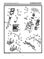
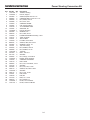
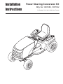
Installation
Instructions
Power Steering Conversion Kit
Mfg. No. 1687286, 1687302
For Prestige / 500 / 1800 / 2800 Series Tractors
Table of Contents
Power Steering Conversion Kit
SECTION CONTENTS
General Information
Safety
Personal Protective Equipment ................................................... 1-1
Battery/Electrolyte Saftey .............................................................1-1
Electrical System Safety ...............................................................1-1
Elevating Unit Safety ....................................................................1-1
Proper Tool Use............................................................................1-1
Work Area Safety..........................................................................1-2
Compressed Air Safety.................................................................1-2
Grease & Lubricant Safety............................................................1-2
General Servicinfg Safety .............................................................1-2
General Repair
Bearings & Bushings ................................................................... 1-3
Belts & Pulleys............................................................................. 1-3
Electrical Parts..............................................................................1-3
Fasteners & Harware....................................................................1-4
Genuine Replacement Parts.........................................................1-4
Hydraulic Parts .............................................................................1-4
Paint..............................................................................................1-4
Reuired Tools & Equipment..........................................................1-4
System Checks.............................................................................1-4
Notes ............................................................................................1-5
Installation Instructions
Kit Contents ................................................................................. 2-1
Parts, Descriptions....................................................................... 2-2
Hitch Replacement .......................................................................2-3
Front Axle Replacement ...............................................................2-3
Steering Replacement ..................................................................2-7
Tilt & Steering Wheel Installation................................................2-11
i
Installation Instructions
Table of Contents
ii
General Information
Safety Rules
SERVICE AND MAINTENANCE
Electrical System Safety
• Wear protective safety glasses whenever using hand
or power tools, shop equipment, and whenever working under power equipment to protect your eyes from
falling debris and small parts.
• Loose connectors, worn wires, damaged wire insulation, and loose termination hardware can cause
sparks, short-circuits, and erratic equipment operation. Always check wiring for damage, and make
appropriate repairs before placing unit back into operation.
• Wear safety goggles or full face protection when handling battery electrolyte fluid, or when performing
grinding or sharpening operations that produce
sparks or flying debris. Extensive grinding may
require the use of protective sleeves and an apron.
• Use care when working around exposed terminals to
prevent short-circuiting the electrical system.
Sparking, electric shocks, and damage to the system
may result from accidental contact between terminals
and metal hand tools.
Personal Protective Equipment
• Wear work gloves when handling sharp surfaces
such as mower blades, or when working around
sharp edges. Never wear gloves that are loose fitting
or that have tie straps, as these could cause your
hands to get caught by rotating parts, resulting in serious injury. Chemical-resistant Rubber gloves are recommended when handling or pouring battery electrolyte.
Elevating Unit Safely
• Always support unit on approved jack stands when
working on an elevated unit, and keep unit from
rolling by engaging parking brake and placing wheel
chocks behind wheels still on floor or work table.
• Secure unit to work-surface of scissor-lift worktables
or other powered lift tables in accordance with the
manufacturer’s instructions. Unsecured units may roll
unexpectedly while work is being done, causing
injuries.
• Steel-toe safety shoes are highly recommended to
protect feet from falling tools, heavy parts, and other
shop equipment.
• Never work under an elevated unit unless it is properly supported by jack stands, locked from rolling with
wheel chocks or equivalent, and you can quickly
escape from under the unit in an emergency using a
rolling device such as a mechanic’s creeper.
Battery/Electrolyte Safety
• Lead-Acid batteries use an electrolyte containing sulphuric acid, a highly corrosive liquid that can cause
severe chemical burns if allowed to come into contact
with skin, or blindness if allowed to contact your eyes.
Always wear approved eye goggles or a full face
shield and protective gloves when handling electrolyte or filling the battery.
• Always protect your eyes from falling debris or small
parts by wearing approved safety glasses or goggles.
• Remove the ignition key and disconnect the spark
plug wires before working under a unit. Accidental or
inadvertent starting could result in serious injuries.
• Lead-acid batteries also produce hydrogen, a colorless, highly explosive gas that can be easily ignited
by a single spark. Charging the battery incorrectly or
hooking up jumper cables improperly can cause
sparking, and must be avoided. Always follow recommended battery charging and jumper cable procedures.
Proper Tool Use
• Use power and hand tools only for the use that they
were designed. Never alter or modify tools, or improvise using tools that are not suitable for the job at
hand.
• When removing or installing battery cables, disconnect the negative cable FIRST, and reconnect it
LAST. If not done in this order, the positive terminal
could be accidentally shorted to the frame by a tool,
creating a dangerous spark that can ignite nearby fuel
vapors or escaping hydrogen gas from the battery.
• Keep battery securely fastened in position with vent
tube directed down and out of battery compartment.
Replace battery if electrolyte leakage occurs. Make
sure the battery vent tube is properly installed, and is
not plugged with clippings or other debris. Replace
the vent tube if cracked, damaged, or missing from
unit.
• Keep all hand and power tools in good repair, and put
them away when done to avoid cluttering the work
area. Use extra care when using corded tools around
moving or rotating parts such as belts and pulleys,
since the cord could get caught and suddenly pull the
tool, or you, into the area of moving parts.
• Always check the unit to ensure that all hand and
power tools and tool attachments have been removed
from the unit after use. Small tools and tool attachments left on the equipment can fall into the cutting
path when the unit is placed into service, and become
a hazard to bystanders if struck by mower blades.
• Old batteries should be disposed of by recycling.
1-1
General Information
Work Area Safety
Safety Rules
General Servicing Safety
• Always keep the work area clear of clutter from discarded parts, and debris from parts boxes or packaging materials. Small parts, hardware items, and other
debris or refuse left lying around can become slip,
trip, and fall hazards if not removed and discarded of
properly.
• Always check safety devices and switches for proper
operation - never alter these devices or make temporary or makeshift repairs. Use only factory-authorized parts and procedures, and check newlyinstalled parts for proper operation.
• Make sure all hardware items are properly tightened,
especially blade attachment bolts. Replace any hardware that appears damaged.
• Always observe general shop safety rules for housekeeping, and tend to oil spills and other spilled fluids
promptly to prevent slip and fall injuries.
• Check brake operation, and adjust or repair as
required. Always comply with factory specifications
on settings and adjustments.
• Allow sufficient work area around the equipment you
are working on to permit comfortable working positions. Never put yourself in a position that would prevent you from escaping quickly in the event of emergencies such as sudden shifts in equipment position,
fire, or other situations requiring an immediate reaction on your part.
• Check grass catcher components for wear, damage,
or deterioration, and replace with factory authorized
parts if necessary.
• Always make repairs using factory authorized
replacement parts only. Using parts that don’t meet
factory specifications can result in sudden or premature failures, poor or erratic equipment performance,
and potential safety hazards to operators and
bystanders.
Compressed Air Safety
• Always use care when using compressed air to blow
dirt and debris off equipment - always direct the air
blast away from yourself and others in the area, and
protect your eyes with safety glasses to prevent injury
from particles that may blow back toward your face.
• Always comply with factory specifications on settings
and adjustments when installing new parts, making
repairs, or performing routine service procedures.
• Never use high pressure air directly against your skin
to clean dirt and debris - the air pressure could actually force foreign material or fluids into your skin,
causing serious injuries.
• Always test repairs before releasing units to customers, paying special attention to any items that are
safety-related. Correct any problems noted, and recheck to ensure that the problems have been fully
remedied.
• Use care when filling tires - lawn and garden tractors
utilize low pressure tires, and over-pressurization is
hazardous to you and anyone who operates the
equipment with improper tire pressures. Always consult the air pressure recommendations for the unit
involved before adding additional air to the tires.
• Make sure all safety and operating instruction decals
are legible, properly located, and securely attached.
Replace any decals that can’t be read or are in danger of falling off.
Grease & Lubricant Safety
• Always advise equipment owners of any potential
operating or safety problems that may be arising due
to anticipated wear, and request that the owner
address the problem before a hazard develops.
• Normal service and maintenance involves the use of
oils and greases that could present a fire hazard if
not handled properly. Always dispose of oily rags
properly to prevent fires caused by spontaneous
combustion.
• Never allow a unit to be placed back into service if a
serious safety or operating problem is evident.
Advise the owner of the problem and the possible
hazards associated with the problem, and request
permission to correct the deficiencies.
• Spilled lubricants pose dangerous slip hazards and
must be taken care of immediately. Wipe up spills
carefully, or use absorbent materials to soak up
spilled fluids. Always dispose of rags, paper towels,
and other saturated absorbent properly.
• Use extreme care when working on older models that
do not have all of the latest safety devices and
switches. Disengage the PTO and transmission
before starting the unit, or commencing repairs.
• Store oils and greases away from flame or other ignition sources. Petroleum-based fluids can be ignited
by smoking materials and sparks - always treat oils
and greases as potentially flammable materials.
Always cap oil and grease containers when done
using, and store or dispose of properly.
• Always use care when removing or installing parts to
prevent damage from dropping or rough handling.
Support heavy parts properly to prevent damage or
personal injury to yourself and others.
1-2
General Information
Safety Rules
GENERAL REPAIR INFORMATION
INSPECTION
Once cleaned, bearings can be properly inspected for
wear, scratches, visible damage such as corrosion,
cracked seals or scorching, and rough, or noisy, operation. Bushings can be visually checked for scratches,
uneven wear, or other visual damage.
In addition to providing specific repair procedures for the
equipment listed at the beginning of this section, this
manual provides the following additional general instructions for dealing with repairs to various types of components.
LUBRICATION
This information is designed to help you deal more effectively with these components by providing basic service
knowledge and other useful tips.
Bearings & Bushings
Roller bearings, ball bearings, and bushings are used to
provide support to rotating shafts and other parts such as
gears, pulleys, and sprockets that are used to transmit
rotary motion. Over time, bearings and bushings may
require additional lubrication to transmit this rotary
motion with minimal friction, or may need replacement
due to normal operation and wear. Normal service for
bearings and bushings includes removal, cleaning,
inspection, lubrication, and replacement.
REMOVAL
Most bearings and bushings used on the listed equipment can be easily removed by following the appropriate
detailed procedures found throughout this manual. Care
should always be exercised to avoid scratching or damaging the bearing or bushing, the mounting shaft, and
surrounding components. Bearing or bushing removal is
usually necessary when excessive play or wobble is
noticed on the part it supports, when unusual noise or
vibration is apparent, or when a burning smell is present
at the bearing location.
CLEANING
Sealed bearings and bushings can be cleaned by careful
wiping with a cloth. Bearings with one-sided or removable shields and plain bushings can be cleaned by
immersion in safety solvent, and brushing with a part
cleaning brush. Oil-impregnated bushings, and bushings
made of nylon or other synthetic materials, can be
cleaned with safety solvents, or wiped clean, but should
not be immersed in solvent for periods longer than that
necessary to remove heavy or caked-on build-ups of
grease. All petroleum-based solvents are flammable, so
appropriate precautions regarding flames, sparks, and
other ignition sources should always be observed.
Gasoline should never be used because of its volatility
and its highly toxic nature.
After passing inspection, bearings and bushings should
be lubricated in accordance with factory specifications,
and reinstalled according to the appropriate installation
instructions. New bearings and bushings must also be
properly lubricated before use. For optimal performance,
and as a practical preventive maintenance measure,
bearings and bushings used in pairs or multiple sets
should all be replaced at the same time.
Belts & Pulleys
Belts and pulleys transmit rotary motion from power
sources to work components, providing the force needed
to drive transmissions, operate mower decks, and power
various attachments. This continual use eventually
causes belts to wear out, and over time may also require
the replacement of pulleys and pulley bearings.
Belt wear and various types of damage are easily
checked by visual examination, which is covered in
greater detail elsewhere in this manual. Pulleys may
also be checked visually for wear or apparent damage,
but pulley bearings usually require removal, cleaning,
and inspection to determine if replacement is required.
Belt and pulley life can be optimized by making sure that
proper belt tension and alignment are observed when
belts are installed. Proper belt tension and alignment
should also be maintained by performing periodic checks
and adjustments. In addition, only factory authorized
replacement belts will minimize problems caused by
size, thermal instability, and variations in quality.
Electrical Parts
The electrical parts used on these units have been
specifically engineered for outdoor power equipment,
and are designed to provide years of reliable operation.
As with all electrical components and systems, electrical
contacts must be kept clean and dry, and all terminations
must be securely fastened or connected. Also, all electrical components, wiring, and connectors should be periodically inspected for corrosion, signs of excessive heat
build-up, or other damage that signals that it is time to
repair or replace the item.
Specific procedures for electrical troubleshooting and
most common repairs is covered in separate sections of
this manual.
1-3
General Information
Safety Rules
Fasteners & Hardware
Required Tools & Equipment
All hardware and fasteners used in this equipment must
meet factory specifications for SAE grade, size, and
torque, and must be kept securely tightened. Locking
hardware that degrades with use should be replaced
when service is performed in affected areas. Always
observe factory specifications for torque, or consult the
torque chart for torque information.
All repairs in this manual can be accomplished with standard mechanic’s hand tools. The use of appropriate
power tools such as impact wrenches and power drivers
may aid in part removal and replacement, but care must
be exercised to avoid causing damage to components
from excessive tightening. Transmission service, steering service, tire and wheel service, and service to components located under the frame also requires the use of
a jack with suitable capacity, and jack stands to support
the unit being worked on.
Genuine Replacement Parts
Only factory authorized replacement parts should be
used when making repairs or performing routine maintenance. The use of parts that do not meet stringent factory specifications can cause poor performance, premature
failures, and lead to potential safety hazards. In addition,
the use of non-factory authorized replacement parts will
void your warranty.
Hydraulic Parts
Hydraulic parts are adversely affected by dirt and contamination, and care must be exercised when performing
service on these parts to prevent foreign material from
entering. Specific service information appears elsewhere in this manual, and all precautions and procedures must be followed when repairing or servicing these
parts.
Systems Checks
In addition to performing individual component service,
components affected by related parts changes should
also receive attention at the time service is performed.
Examples of this include part replacements that are part
of a safety device, electrical components, transmission
components, and pulleys that are part of the same power
delivery system. Giving attention to related parts will
help ensure that the parts most likely to be affected by
the wear of similar or nearby parts, or parts subjected to
the same amount of stress or wear, are given appropriate attention before a failure can occur.
Paint
The paint on outdoor power equipment provides for an
attractive appearance, as well as a barrier to corrosion
caused by exposure to moisture in the environment.
Scratches, abrasions, and other damage to painted surfaces should be repaired promptly to prevent the formation of rust and premature part failure. Factory supplied
paints are available that provide both an accurate color
match and superior corrosion resistance.
1-4
General Information
Safety Rules
NOTES
1-5
Installation Instructions
Power Steering Conversion Kit
Power Steering Conversion Components
8
18
13
15
19
9
7
12
14
16
2
11
5
10
17
6
1
4
20
3
21
22
24
25
24
12
26
34
23
33
12
25
41
32
35
26
37
28
36
29
40
27
39
38
Figure 1. Contents
2-1
30
31
Installation Instructions
Ref
1
2
3
4
5
6
7
8
9
10
11
12
13
14
15
16
17
18
19
20
21
22
23
24
25
26
27
28
29
30
31
32
33
34
35
36
37
38
39
40
41
Part No. Qty.
1733139A 1
1733044A 1
1924856
4
1960655
2
1960636
2
1933988
2
1733363
1
1725024
1
1733790
1
1725294
1
1724685A 1
1924366
3
1960576
1
1733506
1
1733727
1
1733211
1
1733230
2
2860444
4
1916964
4
1701011
3
1935225
2
1960368
6
1732759A 1
1931350
2
1611705
2
1930645
2
1732937A 1
1732439
1
1702779
1
1960355
1
1719725
1
1919262
1
1960713
1
1733912A 1
1960714
1
1734011
1
1709189
1
1713578
1
1960519
1
1733229A 1
1733717A 1
Power Steering Conversion Kit
Description
TOWER, Steering
PLATE, Support
SCREW,Taptite 5/16-18 x 1/2
CARRIAGE BOLT, 5/16-18 x 1-1/4
NUT, KEPS, 5/16-18
NUT, Push, 5/16
STEERING WHEEL
CAP, Steering Wheel
TILT STEERING UNIT
ADAPTER, Titt
PLATE, Mounting
WASHER, 5/8
NUT, HEX, 5/8-18
POWER STEERING Assembly, 5-Port
TUBE, Hydraulic
TEE FITTING
FITTING, Perma-Push
SCREW, HEX, M6 x 16mm
WASHER, LOCK, 1/4
TIE, Self Locking
NUT, SPEED, 5/16-18
NUT, SPEED, 1/4-20
TIE ROD
BOLT, 3/8-16 x 1
SPACER
NUT, Flange, Lock 3/8-16
FRONT AXLE Assembly
STEERING CYLINDER
BALL JOINT
NUT, Hex, Lock ESNA, 1/2-13
SPACER
NUT, Hex, Jam, 1/2-20
SCREW, Hex, M16-110mm
SPACER
NUT, Lock, 1/2-20
PIN, HitchH
PIN, Klik
ROD, 1/2 x 7-5/8
NUT, PUSH, 1/2
HITCH, 54 Inch Mower
HITCH, 44/50 Inch Mower
2-2
Installation Instructions
Power Steering Conversion Kit
NOTE: Read through these instructions, the
SERVICE MANUAL, and OPERATOR’S MANUAL
before beginning installation.
DANGER
PREVENT SERIOUS INJURY OR
DEATH FROM FALLING UNIT
WARNING
Always use a properly working lifting device with
a capacity suitable for the weight of the unit being
serviced.
Before beginning any service work turn off the
PTO, set the parking brake, turn off the ignition,
and disconnect the spark plug wire(s).
Always use a jack stand to support the unit while
performing service and chock remaining wheels
to prevent the unit from rolling off the supports.
INITIAL ASSEMBLY
Hitch Replacement
Never work under or around an elevated unit that
is not properly supported and secured in position
with wheel chocks.
1. Remove mower deck. See OPERATOR’S
MANUAL.
2. Remove hitch (A, Figure 1) from mower deck.
Note: Hardware used to attach leveling rod to hitch must
be saved and re-used during reassembly.
3. Remove spring (D, Figure 1) and lever (C) from
original hitch (A).
Front Axle Replacement
1. Remove hood assembly, dash assembly, seat and
seat deck. See SERVICE MANUAL, Section 15 Hood & Dashboard Service, and Section 16 - Seat
Deck & Fuel Tank Service.
4. Discard original hitch and mounting hardware used to
attach hitch to mower deck.
5. Install spring (D) and lever (C) to new hitch (B)
removed in step 3.
C
NOTE: Clean and remove all debris from work area.
2. Disconnect and remove the battery.
D
A
WARNING
Be careful when handling the battery. Avoid
spilling electrolyte. Keep flames and sparks away
from the battery.
When removing or installing battery cables,
disconnect the negative cable FIRST and reconnect
it LAST. If not done in this order, the positive
terminal can be shorted to the frame by a tool.
B
H
F
3. Block both rear tires to prevent rolling; elevate and
support the front end to allow adequate access for
removal of the front axle.
G
B
E
Figure 2 Hitch Replacement
A. Original Hitch
B.
C. Lever
D.
E. Rod
F.
G. Hitch Pin
H.
New Hitch
Spring
Push Nut
Klik Pin
6. Install new rod (E, Figure 2) to new hitch (B), and
secure in place with push nut (F).
7. Install new hitch (B) to mower deck using new hitch
pin (G) and secure with klik pin (H).
SEE OPERATOR’S MANUAL.
2-3
Installation Instructions
Power Steering Conversion Kit
4. Remove front bumper (A, Figure 3) by removing the
four 5/16-18 Torx screws (C). Save all parts for
reassembly.
9. Remove spacer (A, Figure 5) from original axle center mount (B). Inspect spacer for wear. Replace
spacer if excessive wear is indicated.
5. Remove muffler lower heat shield (B, Figure 3) by
removing the four 1/4-20 whiz lock screws (D). Save
all parts for reassembly.
B
6. Loosen but do not remove all four 3/8-16 support
plate bolts (E, Figure 2).
E
D
A
C
E
D
C
A
Figure 5 Spacer Removal
A. Spacer
B. Original Axle
10. Thread 1/2-20 jam nut (D, Figure 6) onto steering
cylinder (B). Then attach ball joint (C) to steering
cylinder (B).
11 Attach spacer (E), ball joint (C), and 1/2-13 lock nut
(F) to mount (K) on axle as shown.
B
Figure 3 Bumper and Heat Shield Removal
A. Bumper
B. Lower Heat Shield
C. Torx Screws, 5/16-18
D. Whiz Lock Screws, 1/4-20
E. Whiz Lock Screws, Support Plate, 3/8-16
12. Attach steering cylinder (B) to axle (A) using
a M16 x 110mm capscrew (I), two 5/8 flat washers
(H), a spacer (G), and M16 lock nut (J) as shown.
13. Tighten lock nut (J) to 150 ft. lbs (203.4 Nm).
14. Tighten lock nut (F) to 48 ft. lbs (60.3 Nm).
7. Remove front axle and steering linkage. See
SERVICE MANUAL, SECTION 8 - Steering & Front
Wheel Repair.
8. Remove J-hook (A, Figure 4) from original axle (B).
Save J-hook (A), 7/16-14 x 2 capscrews (C), and
7/16-14 lock nuts (D) for installation on new axle.
D
H
J
G
A
H
K
B
I
E
D
C
C
B
A
Figure 4 J-Hook Removal
A. J-Hook
C. Capscrews, 7/16-14 x 2
B. Original Axle
D. Lock Nuts, 7/16-14
F
Figure 6 Steering Cylinder Installation
A. New Axle
B. Steering Cylinder
C. Ball Joint
D. Jam Nut, 1/2-20
E. Spacer
F. Lock Nut, 1/2-13
G. Spacer
H. Flat Washer, 5/8
I. Capscrew, M16 x 110mm J. Lock Nut, M16
K. Mount, Ball Joint
2-4
Installation Instructions
Power Steering Conversion Kit
16. Attach tie rod (B, Figure 8) to new axle (A) using two
spacers (C), two 3/8-16 x 1 square head bolts (D),
and two 3/8-16 flange nuts (E) as shown.
Tighten flange nuts to 19.5 ft. lbs (26.5 Nm).
Do not allow dirt, water, or other debris to
enter the expansion chamber or
transmission. Even a small amount of dirt
can damage the transmission
The hydraulic system is powered by the hydrostatic
transmission charge pump, and subsequently shares oil
with the transmission. It is for this reason that great care
must be taken when adding or replacing hydraulic
system parts to prevent contaminants from entering the
transmission.
17. Clean and grease spacer (B, Figure 9) previously
removed from old axle. Then install spacer (B) into
new axle (A) as shown.
15. Install hydraulic perma-push fittings
(B, Figure 7) to steering cylinder (A) as shown.
A
B
Figure 9 Spacer Installation
A. New Axle
B. Spacer
B
A
Figure 7 Hydraulic Fitting Installation
A. Steering Cylinder
B. Perma-Push Fittings
18. Install j-hook (B, Figure 10) to new axle (A) using two
7/16-14 x 2 capscrews (C), and two 7/16-14 lock nuts
(D) as shown. Tighten lock nuts to 32 ft. lbs (44.2
Nm).
D
B
D
D
C
C
A
E
A
C
B
E
Figure 8 Tie Rod Installation
A. New Axle
B. Tie Rod
C. Spacers
D. Square Head Bolt,
3/8-16 x 1
E. Flange Nut, 3/8-16
Figure 10 J-Hook Installation
A. New Axle
B. J-Hook
C. Capscrew, 7/16-14 x 2
D. Lock Nuts, 7/16-14
2-5
Installation Instructions
Power Steering Conversion Kit
19. Install new axle (A, Figure 11) between axle support
plate (B) and frame (C) using a 5/8-11 x 3-1/2 capscrew (D), two 5/8 flat washers (E), and a 5/8-11
flange nut (F) as shown. Tighten flange nut to 150 ft.
lbs (204 Nm).
22. Tighten all four 3/8-16 support plate bolts
(E, Figure 2) to 19.5 Ft. lbs (26.5 Nm
21. Install heat shield (A, Figure 12) using four 1/4-20
Whiz Lock screws (B) as shown.
Tighten screws to 10 ft. lbs (13.6 Nm).
NOTE: Replace any speed nuts (E) broken or missing
from heat shield with parts from kit.
22. Install bumper (C, Figure 12) using four 5/16-18 x 7/8
Torx screws (D) as shown.
Tighten screws to 7 ft. lbs (9.75 Nm).
NOTE: Replace any speed nuts (F) broken or missing
from bumper mounts with parts from kit.
B
C
B
D
D
D
F
C
C
B
D
A
C
A
Figure 11 New Axle Installation
A. New Axle
B. Axle support Plate
C. Frame
D. Capscrew, 5/8-11 x 3-1/2
E. Flat Washers, 5/8
F. Flange Nut, 5/8-11
E
Figure 12 Bumper and Heat Shield Installation
A. Heat Shield
B. Whiz Lock Screws, 1/4-20
C. Bumper
D. Torx Head Screw, 5/16-18 x 7/8
E. Speed Nut, 1/4-20
F. Speed Nut, 5/16-18
2-6
Installation Instructions
Power Steering Conversion Kit
Steering Replacement
Tear-down and Removal of Steering System
NOTE: Attach new push nuts to carriage bolts (supplied
with kit) as required.
2. Attach new power steering unit (B, Figure 14) to new
tower (A) using four M6 x 16 mm screws (C), and
four 1/4 lockwashers (D).
Tighten screws to 97 in. lbs (10.96 Nm).
1. See the SERVICE MANUAL, Section 10 Hydraulic System Service for removal and
installation of the valve control spool.
2. Remove the control spool & support from the tower
assembly, and save all hardware for reinstallation.
3. Disconnect and discard the return side tube to the
control spool.
4. Disconnect and discard T-fitting, and tube to
transmission between torque generator and control
spool.
5. See the SERVICE MANUAL, Section 8 - Steering &
Front Wheel Repair for removal of steering wheel,
torque generator, steering gear, and drag link.
6. Remove and discard the steering wheel, mounting
plate, tilt steering unit, tilt adapter, steering shaft,
steering mounting plate, steering gear assembly,
torque generator, and drag link.
C
7. Remove and discard tower.
New Steering System Assembly
D
1. Install steering support plate (B, Figure 13) into new
tower (A) using four 5/16-18 x 1/2 Taptite screws (C).
Tighten screws to 7 ft. lbs (9.75 Nm).
A
B
C
Figure 14 Power Steering Installation
A. New Tower
B. New Power Steering Unit
C. Screws, M6 x 16 mm
D. Lock Washers, 1/4
B
C
A
Figure 13 Steering Support Plate Installation
A. New Tower
B. New Steering Support Plate
C. Taptite Screws, 5/16-18 x 1/2
2-7
Installation Instructions
Power Steering Conversion Kit
NOTE: For initial installation, only two screws are used
(as shown) and the screws are to be loosely installed to
allow the tower to pivot.
4. Install control valve spool and support (B, Figure 16)
to the new tower (A) using (previously removed) four
5/16-18 x 3/4 carriage bolts (C), and four 5/16-18
KEPS lock nuts (D).
Tighten lock nuts to 7 ft. lbs (9.75 Nm).
3. Attach new tower assembly (A, Figure 15) to frame
(A) using two 3/8-16 x 3/4 taptite screws (C).
B
A
D
C
A
C
C
B
Figure 15 Tower Assembly Installation
A. New Tower Assembly
B. Frame
C. Taptite Screws, 3/8-16 x 3/4
Figure 16 Control Valve Spool & Support Installation
A. New Tower Assembly
B. Control Valve Spool & Support
C. Carriage Bolts, 5/16-18 x 3/4
D. Lock Nuts, KEPS, 5/16-18
2-8
Installation Instructions
Power Steering Conversion Kit
A
E
B
G
L
D
C
F
I
H
J
L
K
Figure 17 Power Steering & Hydraulic Hose
Installation
A. Power Steering Unit
B. Control Valve Spool
C. Three-way “T”
D. Hydraulic Tube (from Port P to Transmission)
E. Hydraulic Hose (Port T) to “T” fitting
F.
G.
H.
I.
J.
K.
L.
5. Attach existing tube (K, Figure 17), and existing tube
(J) to new three-way “T” (C) as shown.
8. Route hydraulic hoses(G) and (H) (labeled “Port R”
and “Port L”) out the bottom of the bulkhead heatshield, and through the frame as shown in Figure 17
and Figure 19.
6. Wrap hydraulic hose (E) (labeled “Port T”) around the
back of the power steering unit (A), and attach it to
the new three-way “T” (C) as shown.
7. Loop hydraulic hose (I) (labeled “Port E”) around the
front of the power steering unit (A), and attach the
hose fitting to the control valve spool (B) as shown.
Hydraulic Hose (Port P) to hydraulic tube
Hydraulic Hose (Port R) to steering cylinder
Hydraulic Hose (Port L) to steering cylinder
Hydraulic Hose (Port E) to control valve spool
Hydraulic Tube to Transmission from “T” fitting
Hydraulic Tube from spool to “T” fitting
Taptite Screws, 3/8-16 x 3/4
9. Attach hydraulic tube (D) to hydraulic hose (F)
(labeled “Port P”) as shown.
10. Install two 3/8-16 x 3/4 Taptite screws (L) as shown.
Tighten all four screws to 30 ft. lbs (40.8 Nm).
2-9
Installation Instructions
Power Steering Conversion Kit
11. Attach hydraulic tube (B, Figure 18) to transmission
(A) as shown.
D
B
A
B
C
Figure 18 Hydraulic Tube to Transmission
A. Transmission Port
B. Hydraulic Tube
A
Figure 20 Steering Hose Connection
A. Steering Cylinder
B. Hydraulic Hose (labeled “Port L”)
C. Hydraulic Hose (labeled “Port R”)
D. Tie Wraps
12. Route and attach hydraulic hose (B, Figure 20)
(labeled “Port L”) to hose fitting on left side of steering cylinder (A) as shown.
C
A
D
B
Figure 19 Hydraulic Hose Routing
A. Bulkhead Heatshield
B. Frame
C. Hydraulic Hose (labeled “Port R”)
D. Hydraulic Hose (labeled “Port L”)
13. Route and attach hydraulic hose (C) (labeled “Port
R”) to hose fitting on right side of steering cylinder (A)
as shown.
14. Secure hydraulic hoses (B) and (C) to frame using
tie wraps (D) as shown.
NOTE: The hoses must be secured to the frame to
prevent any movement and prevent contact with the
steering or clutch.
2-10
Installation Instructions
Power Steering Conversion Kit
Tilt & Steering Wheel Installation
Battery, Dash, Seat Deck, Seat, and Hood
Assembly Installation
1. Install battery, but DO NOT connect.
2. Install seat deck and seat. See the SERVICE
MANUAL, Section 16 - Seat Deck & Fuel Tank
Service.
8. Install mower deck. See the OPERATOR’S
MANUAL.
9. Start tractor and verify all hose connections are tight
and do not leak.
10. Check fluid level of transmission and add fluid as
necessary. See the SERVICE MANUAL, Section 3
- Maintenance Procedures for fluid requirement and
levels.
3. Install dash assembly, and hood assembly. See the
SERVICE MANUAL, Section 15 - Hood &
Dashboard Service.
L
4. Install front tires. See the SERVICE MANUAL,
Section 8 - Steering & Front Wheel Repair.
J
I
K
Base, Tilt, Boot, and Steering Wheel
Installation
1. Attach tilt adapter (C, Figure 21) to tilt assembly (F),
and secure in place with included fastener.
H
2. Attach mounting plate (D), spacers (E), tilt
assembly (F) to dash (A) using installed carriage
bolts (B), and two 5/16-18 KEPS nuts (G) as shown.
Tighten nuts to 23 ft. lbs (31 Nm).
3. Install boot (H) over tilt assembly (F) so that tilt lever
extends out of boot.
G
NOTE: Make sure that base of boot (H) is secured to
mounting plate (D) - boot over lip edge of base.
G
F
4. Install steering wheel (I) onto tilt assembly (F).
Secure using a 5/8 washer (J), and a 5/8-18 nut (K).
Tighten nut to 180-240 in. lbs (20.3-27.1 Nm).
E
D
5. Attach steering wheel cap (L) to steering wheel (I).
Tabs on cap snaps into slots on steering wheel.
C
B
6. Check and verify that all parts removed have been
reinstalled, and tightened correctly.
A
WARNING
Be careful when handling the battery. Avoid
spilling electrolyte. Keep flames and sparks away
from the battery.
When removing or installing battery cables,
disconnect the negative cable FIRST and reconnect
it LAST. If not done in this order, the positive
terminal can be shorted to the frame by a tool.
7. Connect battery. See the OPERATOR’S MANUAL Battery Maintenance.
Figure 21 Base, Tilt, Boot and Steering Wheel
Installation
A. Dash
B. Carriage Bolts
C. Tilt Adapter
D. Mounting Plate
E. Spacers
F. Tilt Assembly
G. KEPS Nuts, 5/16-18
H. Boot
I. Steering Wheel
J. Washer, 5/8
K. Nut, 5/8-18
L. Steering Wheel Cap
2-11
Installation Instructions
Torque Specifications
Hardware Identification & Torque Specifications
Common Hardware Types
Torque Specification Chart
Hex Head Capscrew
FOR STANDARD MACHINE HARDWARE (Tolerance ± 20%)
Washer
Hardware
Grade
Lockwasher
Carriage Bolt
No
Marks
SAE Grade 2
Hex Nut
Size Of
Hardware
Standard Hardware Sizing
8-32
8-36
10-24
10-32
1/4-20
1/4-28
5/16-18
5/16-24
3/8-16
3/8-24
7/16-14
7/16-20
1/2-13
1/2-20
9/16-12
9/16-18
5/8-11
5/8-18
3/4-10
3/4-16
7/8-9
7/8-14
1-8
1-12
When a washer or nut is identified as 1/2”, this is the
Nominal size, meaning the inside diameter is 1/2 inch; if a
second number is present it represent the threads per inch
When bolt or capscrew is identified as 1/2 - 13 x 2”, this
means the Nominal size, or body diameter is 1/2 inch; the
second number represents the threads per inch (13 in this
example, and the final number is the body length of the
bolt or screw (in this example 2 inches long).
The guides and ruler furnished below are designed to
help you select the appropriate hardware and tools.
0
1/4
Nut, 1/2”
1/2
Inside
Diameter
3/4
1
1/4
1/2
3/4
Screw, 1/2 x 2
2
1/4
Body
Diameter
in/lbs
ft/lbs
19
20
27
31
66
76
11
12
20
23
30
35
50
55
65
75
90
100
160
180
140
155
220
240
Nm.
2.1
2.3
3.1
3.5
7.6
8.6
15.0
16.3
27.2
31.3
40.8
47.6
68.0
74.8
88.4
102.0
122.4
136
217.6
244.8
190.4
210.8
299.2
326.4
SAE Grade 5
in/lbs
ft/lbs
30
31
43
49
8
10
17
19
30
35
50
55
75
90
110
120
150
180
260
300
400
440
580
640
SAE Grade 8
Nm.
in/lbs
ft/lbs
Nm.
3.4
3.5
4.9
5.5
10.9
13.6
23.1
25.8
40.8
47.6
68.0
74.8
102.0
122.4
149.6
163.2
204.0
244.8
353.6
408.0
544.0
598.4
788.8
870.4
41
43
60
68
12
14
25
27
45
50
70
80
110
120
150
170
220
240
386
420
600
660
900
1,000
4.6
4.9
6.8
7.7
16.3
19.0
34.0
34.0
61.2
68.0
95.2
108.8
149.6
163.2
204.0
231.2
299.2
326.4
525.0
571.2
816.0
897.6
1,244.0
1,360.0
NOTES
1. These torque values are to be used for all hardware
excluding: locknuts, self-tapping screws, thread forming
screws, sheet metal screws and socket head setscrews.
2. Recommended seating torque values for locknuts:
a. for prevailing torque locknuts - use 65% of grade 5
torques.
b. for flange whizlock nuts and screws - use 135% of
grade 5 torques.
3. Unless otherwise noted on assembly drawings, all torque
values must meet this specification.
1/2
Body
Length
3/4
3
1/4
1/2
3/4
4
Wrench & Fastener Size Guide
1/4
5/16
3/8
7/16
DIA.
1/2
DIA.
NOTES
MANUFACTURING, INC.
500 N Spring Street / PO Box 997
Port Washington, WI 53074-0997 USA
Form No. 1733944-00
Rev. 02/2007
TP 200-4492-00-SK-SMAN
Briggs & Stratton Yard Power Products Group
Copyright © 2007 Briggs & Stratton Corporation
Milwaukee, WI USA. All Rights Reserved