1
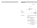
BOSCH
Cooktop
MAKERS WARRANTY
Booklet designed and produced by DESIGN MAXIM. (03) 0853 7491
Model No’s: PCH 612 DAU
PCH 615 DAU
PCH 615 FAU
BOSCH
Part No: W1532
Version (Bosch) A
USER INSTRUCTIONS
INSTALLATION INSTRUCTIONS
MAINTENANCE INSTRUCTIONS
This cooktop is for use with Natural and Propane gases
Leave these instructions with the owner
Wiring diagram
A.
B.
C.
D.
E.
Switch
Blue wire
Brown wire
Terminal
Ignition module
Service agent
For service to this appliance please call an authorised Bosch
service agent or register you fault by phoning us on the numbers listed below.
Toll free
Melbourne:
1300 30 70 37
(head office)
Sales, Customer and Technical Service
New Zealand: 0800 4BOSCH
0800 426 724
Sales and Customer Service
Robert Bosch (Australia) Pty. Ltd
(Incorporated in Victoria) ABN 48 004 315 628
Victoria:
Cnr. Centre & McNaughton Roads,
Clayton, 3168
Phone: (03) 9541 5555
Fax: (03) 9541 5595
New Zealand: 14-16 Constellation Drive, Mairangi Bay,
Auckland, 1310
Phone: (09) 478 6158
Fax: (09)478 2914
2
15
Service
Trouble shooting
chart
Contents
It is not always necessary to call the Service Centre. In
some cases, you may be able to solve the problem
yourself. This table contains some useful information.
Important:
Only authorised personnel from the Service Centre
are qualified to work on the main gas and electric
systems.
Contents ....................................................... 3
Safety considerations ...................................... 4
For your safety .......................................... 4
What to do if you smell gas ......................... 4
Warnings ................................................. 4
Installation ..................................................... 6
What’s wrong
Possible cause
...If none of the electrical • Power turned off.
systems work.
• Faulty fuse.
• The automatic circuit
breaker or mains.
differential has been
triggered.
...If the electronic ignition • There may be food or
system does not work.
cleaning product
particles between the
spark plugs and the
burners.
...If the flame on the
burners is not evenly
distributed.
...If the safety cut-off
devices on the different
burners do not work.
Preparing to install ..................................... 6
• Turn power on.
• Check the fuse in the main
fuse box and replace if faulty.
• Check to see if the circuit
breaker or a differential has
been triggered in the mains
supply box.
Clearances ............................................... 7
• The gap between the spark
plug and the burner needs to
be cleaned carefullly.
Installation of cooktop into kitchen bench ....... 7
Installation procedure ............................. 7
Connection ............................................... 8
Electrical connection .............................. 8
Gas connection ..................................... 8
Conversion from Nat. Gas to Propane Gas .... 9
To change injectors ................................ 9
• The burner components • Put the components in their
have not been
correct positions.
assembled properly.
• The gas ports on the
• Clean the gas ports on the
burners are dirty.
burners.
...If the gas flow does not • The isolation valve is
seem normal or there
closed.
is no gas flow at all.
• If the gas is supplied
from a gas bottle, it
may be empty.
...If the kitchen smells
of gas.
Solution
• Open the isolation valve.
• Replace the gas bottle with a
full one.
• One of the valves has
been left open.
• Possible leak on the
gas bottle coupling.
• Check to see if a valve has
been left open.
• Check that the coupling on
the gas bottle is in order.
• The control knob has
not been kept
pressed in for long
enough.
• The burner ports are
dirty.
• Once ignited, keep the
control pressed in for a few
seconds.
• Clean the burner ports.
Injector size chart .................................. 9
Minimum flame adjustment ................... 10
Operating instructions ................................... 11
Burner location ........................................ 11
Burner ignition & control ........................... 11
User instructions ........................................... 12
Boiling burners ........................................ 12
Wok trivet .......................................... 12
Wire coffee support ............................. 12
Cleaning and care ................................... 13
Do’s .................................................. 13
Don’t ................................................. 13
Service ....................................................... 14
Trouble shooting ...................................... 14
Wiring diagram ...................................... 15
Service contact telephone numbers ............. 15
14
3
Safety considerations
For your safety
• If the information in this manual is not followed exactly, a fire or explosion may result causing property damage, personal injury or death.
• Do not store articles on or against this appliance.
• Do not store flammable materials near this appliance.
• Do not spray aerosols in the vicinity of this appliance while it is in operation.
What to do if you
smell gas
• Do not try to light the appliance.
• Do not touch any electrical switch; do not use any
phone in your building.
• Immediately call your gas supplier from a neighbour’s
phone. Follow the gas supplier’s instructions.
• If you cannot reach your gas supplier, call the fire
department.
• Installation and service must be performed by an
authorised person.
Warnings
1.
2.
3.
4.
5.
6.
7.
8.
4
Do not allow the flame to extend beyond the edge
of the cooking utensil. This instruction is based on
safety considerations.
Do not forget that the unit becomes hot when in
use. Common sense is important. Just because
the flame is out, does not mean parts cannot still
be hot.
This appliance shall not be used for space heating. This instruction is based on safety considerations.
Be sure to disconnect the electrical supply before
disassembly of the appliance.
Keep the appliance area clear and free from combustible materials, gasoline and other flammable
vapours and liquids.
This appliance must be installed in a position
with the proper level of ventilation. Do not obstruct the flow of combustion and ventilation air.
Cabinets installed above the gas cooktop must
have a minimum clearance of 650 mm (24”).
The gas pressure regulator supplied with the appliance must be installed in line with the gas pipe.
(N.G. only)
Cleaning
Do’s
•Once the appliance is cold, clean it with a sponge
and soapy water. Remove any spills immediately.
This will avoid unnecessary effort later.
• Allow burners and trivets to cool down before cleaning them.
• The burners and trivets must be cleaned regularly to
keep them in good condition. This is done by submerging them in soapy water and scrubbing them
with a non-metal brush to keep the ports and slots
free from obstructions so they give a perfect flame.
Dry the burner caps and trivets whenever wet or
damp.
• After cleaning and drying ensure that the burner
heads and caps are replaced correctly on the burner
body. Refer Fig. 6.
• The high temperatures generated by using the wok
burner may cause the stainless steel hob of your
hotplate to become discoloured over time. THIS IS
NORMAL. Clean the hob with a product suitable
for cleaning stainless steel.
• The trivets on your hob are fitted with rubber feet.
Be careful when cleaning as they may be dislodged
during cleaning, leaving the stainless steel hob unprotected and subject to surface scratching .
Don’t
• Never use abrasive products, sharp objects, steel
scouring pads, knives, etc., to remove stubborn food
remains from the hob surface, trivets and burners.
• Do not allow acidic products such as vinegar, lemon
juice, etc., to come into contact with the hob.
13
User instructions
Boiling burners
Use ‘High flame’ setting to bring the pan to the boil,
then adjust the flame between ‘High flame’ and ‘Low
flame’ to maintain the required pan temperature.
Important:
The use of a cooktop leads to the production of heat
and moisture in the kitchen. For this reason make sure
that the room is properly ventilated. Keep natural ventilation openings, such as windows, open or provide
a mechanical ventilation device (e.g. a range hood or
overhead exhaust fan).
For safety and economic gas usage you should always use the correct pan on the correct burner. Flames
should not protrude beyond the base of the pan. You
will save energy, time and money by always placing
the correct pan size on the correct gas ring.
See Fig. 15.
9.
For pressure testing in excess of 3.5 kPa
(1/2 psig) the appliance and its individual shutoff valve must be disconnected from the gas supply piping system.
10. Important
When using a very large pot, leave a gap of at
least 50 mm (2”) to avoid damaging any parts in
bench top wood, plastic or other non-heat resistant
materials. Never leave oil or hot fat unattended.
Note: To avoid jeopardising the electrical safety of the
appliance, it is forbidden to use high-pressure or steam
jet cleaning devices.
15
The chart below gives the correct pan usage for each
burner.
Burner
Small burner
Medium &
wok burner
Recommended
pan diameter
100 - 240 mm
Minimum
pan diameter
100 mm
180 - 260 mm
180 mm
Wok trivet
The hotplate is supplied with an extra wok trivet. This
trivet must be used when using the wok burner for
receptacles with diameters of more than 26cm diameter, griddle plates and all kinds of concave receptacles such as woks, etc.
Wire coffee support
This support is for use only with the small burner when
supporting receptacles with a diameter of less than
10cm.
12
5
Operating instructions
Installation
Preparing to install
This installation must conform with the following:
• Manufacturer’s Installation instructions
• Local Gas Fitting Regulations
• Municipal Building Codes,
• AGA Installation Code for Gas Burning Appliances. (AS 5601/AG 601)
• S.A.A. Wiring Code
• Local Electrical Regulations
• Any other statutory regulations
These built-in hobs are intended to be inserted in a
benchtop cutout.
Only an authorised person should connect the appliance.
Installation dimensions are shown in Fig.1
Burner locations
13
1. Medium burner
2. Medium burner
Burner ignition &
control
3. Wok burner
5. Small burner
Depress control knob and turn anti-clockwise to ‘High
flame’ position. Hold the knob down for a few seconds until the flame ignites. Keep control knob depressed for a few seconds to activate the flame failure
device. If ignition fails, depress knob again and wait
for ignition. Turn anti-clockwise to set the flame to the
desired intensity.
All burners are fitted with a flame failure device which
shuts off the gas supply if the flame extinguishes for
any reason. To re-ignite, wait 30 seconds for any
unburnt gas to disperse before repeating the ignition
procedure described above.
To turn off the gas supply to a burner turn the control
knob clockwise to the ‘OFF’ position. (Refer Fig. 14)
1
Before connecting the unit, check whether the local
connection conditions (type of gas) are compatible
with the unit’s settings. Observe any special conditions imposed by local suppliers (utilities). The specifications of this cooktop are stated on the data label
located on the bottom of the cooktop base.
6
14
The control knob is used to adjust the flame of the gas
burner.
‘Low flame’ graphic = lowest output
‘High flame’ graphic = highest output
11
Minimum flame adjustment
1 Turn the control knob to minimum.
2 Remove the control knob from the valve spindle.
Refer Fig. 8.
3 Using a screwdriver carefully pry off the hard plastic seal. Refer Fig. 9.
4 Using a small screwdriver carefully remove the soft
rubber seal. Refer Fig. 10.
5 The adjustment screw is positioned at the rear lower
section of the valve. Refer Fig. 11 & 12.
6 To adjust the minimum flame for N.G. replace the
control knob onto the spindle, light the gas and
turn the control knob to the small flame position.
Screw the adjustment screw anti-clockwise to establish a minimum stable flame position. The flame
should remain alight and not burn back to the injector when the valve is turned quickly from ‘Full
On’ to the “Minimum flame” position and back a
few times.
To adjust the minimum flame position for LP Gas
the screw must be fully tightened down clockwise.
7 Remove the control knob, replace the seals in reverse order and refit the control knob.
8
9
10
11
12
10
Clearances
A range hood fitted above the top must be installed
according to the installation instructions for the range
hood. A minimum distance of 650 mm is required for
a range hood and 750 mm for an exhaust fan.
If the distance measured from the periphery of the
nearest burner to any vertical surface is less than 200
mm, the surface shall be protected in accordance with
clauses 5.12.1 & 5.12.1.2 of AS 5601/AG 601.
Leave a space at least 100mm between any drawer,
partition or oven that is installed underneath the
cooktop.
Minimum thickness of benchtop is 15mm. See Fig. 2.
2
Installation of cooktop
into the kitchen bench
Installation procedure:
1. For cutout dimensions and clearances refer Fig 1.
2 The hotplate is factory fitted with sealing tape
around the lower edge of the hob and two pressure clamps front and rear. The seal keeps the entire work surface watertight and prevents spillage
from leaking into cupboards underneath. Please
ensure that the sealing tape is not disturbed during
the installation process. Refer Fig. 3.
3
3 Place hotplate on top of the bench cut-out and press
down firmly on all edges at the same time to ensure that the hob is resting on its entire perimeter.
NOTE: If it is necessary to dismount the hob, press
upwards only from underneath.
7
Installation continued
Connection
Electrical:
An electrical 10 amp socket needs to be within 1 m of
the hotplate to allow electrical connection. The socket
must remain accessible after installation of the appliance.
Important note:
This appliance is connected to the mains (240 VAC)
by means of the connecting lead which must be fixed
to the kitchen unit to prevent it from coming into contact with hot parts of the hob (or an oven installed
underneath).. When making this connection make sure
that the lead cannot come into contact with hot parts
of the hob.
Important: This appliance must be earthed.
Converting the cooktop To change injectors
Request change-over injectors from our customer servfrom Nat. Gas to
ice department (refer injector chart below for sizes).
Propane Gas
Natural Gas
Burner
Injector Hourly Gas
size(mm) Consumption
(mm)
(MJ)
Gas:
Left Front (wok) 1.70
During the planning stage, consider the position of
supply connections.
The hob must be connected to the gas supply with
upstream connection of an isolation valve in accordance with the respectively valid regulations. We recommend that the isolation valve be fitted prior to the
cooktop to enable isolation of cooktop from gas supply. The valve must be easily accessible at all times.
To find out the factory set gas type, see bottom of
cooktop next to gas connection.
Remove plastic cap from gas supply line prior to installation.
Fit regulator (N.G.) or Propane fitting (Propane) directly to the R1/2” connection as per Fig. 4 and Fig. 5.
Direction of gas flow is indicated on the rear of the
regulator.
For position of the inlet connection refer Fig.1.
Left Rear
Right Front
Right Rear
1.20
Natural gas connection
4
8
It should be expressly noted that we cannot accept
any liability for direct or indirect damage caused by
wrong connection or improper installation. When
being repaired, the appliance must always be
disconnected from the mains supply; if required,
notify our customer service.
Propane Gas
Injector Hourly Gas
size (mm) Consumption
(mm)
(MJ)
14.0
0.97
13.25
1.20
6.5
0.67
6.25
0.90
4.0
0.5
3.25
6.5
0.67
6.25
Before conversion the cooktop must be disconnected
from the electricity and gas valves must be turned to
the OFF position.
1 Remove the trivets, burner caps and burner heads.
Refer Fig. 6
2 Change the injectors using a 7-mm socket wrench
and be sure to tighten them down properly so that
they are fully airtight. Refer Fig. 7.
3 Re-assemble the burner component parts in reverse
order.
NOTE: it is not necessary to adjust the primary air
control on these burners.
Propane gas connection
5
6
7
9