1
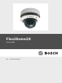
FlexiDome2X
VDN-0498
en
Installation Manual
FlexiDome2X
Table of Contents | en
3
Table of Contents
1
Safety
5
1.1
Safety precautions
5
1.2
Important safety instructions
6
1.3
Connection in outdoor applications
7
1.3.1
Safety precautions
7
1.4
FCC information
9
1.5
UL certification
11
1.6
Bosch notice
11
2
Introduction
13
2.1
Features
13
3
Installation
15
3.1
Unpacking
15
3.2
Disassembly
16
3.3
Mounting the unit
17
3.3.1
Mounting tips
17
3.3.2
Flush mounting
18
3.3.3
Surface mounting
19
4
Connection and set-up
21
4.1
Power and video connections
21
4.2
Setting up the camera
23
4.2.1
Camera positioning
23
4.2.2
Menu navigation
25
4.2.3
Focal length and focus
26
4.2.4
Heater
26
4.2.5
Closing the unit
27
5
Configuration
29
5.1
Menu access
29
5.1.1
Main menu
29
5.1.2
Install menu
29
Bosch Security Systems
Installation Manual
AR18-08-B010 | v1.0 | 2009.03
4
en | Table of Contents
FlexiDome2X
5.2
Pre-defined modes
5.3
Day/Night switching
30
31
5.4
Camera control communication (Bilinx)
31
5.5
Main menu structure
32
5.5.1
Mode submenu
32
5.5.2
ALC submenu
33
5.5.3
Shutter/AGC submenu
34
5.5.4
Day/Night submenu
35
5.5.5
Enhance / Dynamic Engine submenu
37
5.5.6
Color submenu
38
5.5.7
VMD submenu
39
5.6
Install menu structure
41
5.6.1
Language submenu
42
5.6.2
Connections submenu
42
5.6.3
Test signal submenu
43
5.6.4
Camera ID submenu
44
5.6.5
Privacy masking submenu
45
5.6.6
Defaults submenu
45
6
Troubleshooting
47
6.1
Resolving problems
47
6.2
Customer service
47
7
Maintenance
49
7.1
Repairs
49
7.1.1
Transfer and disposal
49
8
Technical Data
51
8.1
Specifications
51
8.1.1
Dimensions
53
8.1.2
Accessories
55
Glossary
57
AR18-08-B010 | v1.0 | 2009.03
Installation Manual
Bosch Security Systems
FlexiDome2X
Safety | en
1
Safety
1.1
Safety precautions
5
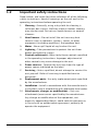
DANGER!
High risk: This symbol indicates an imminently hazardous
situation such as "Dangerous Voltage" inside the product.
If not avoided, this will result in an electrical shock, serious
bodily injury, or death.
WARNING!
!
Medium risk: Indicates a potentially hazardous situation.
If not avoided, this could result in minor or moderate bodily
injury.
CAUTION!
!
Low risk: Indicates a potentially hazardous situation.
If not avoided, this could result in property damage or risk of
damage to the unit.
Bosch Security Systems
Installation Manual
AR18-08-B010 | v1.0 | 2009.03
6
en | Safety
1.2
FlexiDome2X
Important safety instructions
Read, follow, and retain for future reference all of the following
safety instructions. Heed all warnings on the unit and in the
operating instructions before operating the unit.
1.
Cleaning - Generally, using a dry cloth for cleaning is
sufficient but a moist, fluff-free cloth or leather shammy
may also be used. Do not use liquid cleaners or aerosol
cleaners.
2.
Heat Sources - Do not install the unit near any heat
sources such as radiators, heaters, stoves, or other
equipment (including amplifiers) that produce heat.
3.
Water - Never spill liquid of any kind on the unit.
4.
Lightning - Take precautions to protect the unit from
power and lightning surges.
5.
Controls adjustment - Adjust only those controls specified
in the operating instructions. Improper adjustment of
other controls may cause damage to the unit.
6.
Power sources - Operate the unit only from the type of
power source indicated on the label.
7.
Servicing - Unless qualified, do not attempt to service this
unit yourself. Refer all servicing to qualified service
personnel.
8.
Replacement parts - Use only replacement parts specified
by the manufacturer.
9.
Installation - Install in accordance with the manufacturer's
instructions and in accordance with applicable local codes.
10. Attachments, changes or modifications - Only use
attachments/accessories specified by the manufacturer.
Any change or modification of the equipment, not
expressly approved by Bosch, could void the warranty or,
in the case of an authorization agreement, authority to
operate the equipment.
AR18-08-B010 | v1.0 | 2009.03
Installation Manual
Bosch Security Systems
FlexiDome2X
1.3
1.3.1
Safety | en
7
Connection in outdoor applications
Safety precautions
Coax grounding: If an outside cable system is connected to the
unit, ensure that the system is grounded.
U.S.A. models only: Section 810 of the National Electrical Code,
ANSI/NFPA No.70, provides information regarding proper
grounding of the mount and supporting structure, grounding of
the coax to a discharge unit, size of grounding conductors,
location of discharge unit, connection to ground electrodes,
and requirements for the grounding electrode.
Power lines: An outdoor system should not be located in the
vicinity of overhead power lines, electrical lights, or power
circuits, or where it may contact such power lines or circuits.
When installing an outdoor system, extreme care should be
taken to keep from touching power lines or circuits, as this
contact may be fatal. U.S.A. models only - refer to the National
Electrical Code Article 820 regarding installation of CATV
systems.
24 VAC power source: This unit is intended to operate with a
limited power source, this power source must comply with
EN60950. The unit is intended to operate at 24 VAC. User
supplied wiring, from 24 VAC supply to unit, must be in
compliance with electrical codes (Class 2 power levels). Do not
ground the 24 VAC supply at the terminals or at the unit's
power supply terminals.
Connection: The unit has connection terminals on flying leads.
In wet or outdoor installations make use of the VDA-455SMB
accessory or use a field wiring box with Nema 3 or IP55
protection level or better. Make the connections inside the
water tight compartment. After connections are made ensure
that the watertight compartment is tightly closed and cables
and conduits are properly sealed to prevent ingress of water.
Bosch Security Systems
Installation Manual
AR18-08-B010 | v1.0 | 2009.03
8
en | Safety
FlexiDome2X
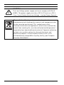
CAUTION!
!
The Low Voltage power supply unit must comply with EN/UL
60950. The power supply must be a SELV-LPS unit or a SELV Class 2 unit (Safety Extra Low Voltage - Limited Power Source).
Disposal - Your Bosch product was developed and
manufactured with high-quality material and components that
can be recycled and reused. This symbol means that
electronic and electrical appliances, which have reached the
end of their working life, must be collected and disposed of
separately from household waste material. Separate collecting
systems are usually in place for disused electronic and
electrical products. Please dispose of these units at an
environmentally compatible recycling facility, per European
Directive 2002/96/EC
AR18-08-B010 | v1.0 | 2009.03
Installation Manual
Bosch Security Systems
FlexiDome2X
1.4
Safety | en
9
FCC information
FCC & ICES Information
(U.S.A. and Canadian Models Only)
This equipment has been tested and found to comply with the
limits for a Class B digital device, pursuant to part 15 of the
FCC Rules. These limits are designed to provide reasonable
protection against harmful interference in a residential
installation. This equipment generates, uses, and can radiate
radio frequency energy and, if not installed and used in
accordance with the instructions, may cause harmful
interference to radio communications. However, there is no
guarantee that interference will not occur in a particular
installation. If this equipment does cause harmful interference
to radio or television reception, which can be determined by
turning the equipment off and on, the user is encouraged to try
to correct the interference by one or more of the following
measures:
–
reorient or relocate the receiving antenna;
–
increase the separation between the equipment and
–
connect the equipment into an outlet on a circuit different
receiver;
from that to which the receiver is connected;
–
consult the dealer or an experienced radio/TV technician
for help.
Intentional or unintentional modifications, not expressly
approved by the party responsible for compliance, shall not be
made. Any such modifications could void the user's authority to
operate the equipment. If necessary, the user should consult
the dealer or an experienced radio/television technician for
corrective action.
The user may find the following booklet, prepared by the
Federal Communications Commission, helpful: How to Identify
and Resolve Radio-TV Interference Problems. This booklet is
available from the U.S. Government Printing Office,
Washington, DC 20402, Stock No. 004-000-00345-4.
Bosch Security Systems
Installation Manual
AR18-08-B010 | v1.0 | 2009.03
10
en | Safety
FlexiDome2X
Informations FCC et ICES
(modèles utilisés aux États-Unis et au Canada uniquement)
Suite à différents tests, cet appareil s'est révélé conforme aux
exigences imposées aux appareils numériques de classe B, en
vertu de la section 15 du règlement de la Commission fédérale
des communications des États-Unis (FCC), et en vertu de la
norme ICES-003 d'Industrie Canada. Ces exigences visent à
fournir une protection raisonnable contre les interférences
nuisibles lorsque l'appareil est utilisé dans le cadre d'une
installation résidentielle. Cet appareil génère, utilise et émet
de l'énergie de radiofréquences et peut, en cas d'installation ou
d'utilisation non conforme aux instructions, engendrer des
interférences nuisibles au niveau des radiocommunications.
Toutefois, rien ne garantit l'absence d'interférences dans une
installation particulière. Il est possible de déterminer la
production d'interférences en mettant l'appareil
successivement hors et sous tension, tout en contrôlant la
réception radio ou télévision. L'utilisateur peut parvenir à
éliminer les interférences éventuelles en prenant une ou
plusieurs des mesures suivantes:
–
Modifier l'orientation ou l'emplacement de l'antenne
réceptrice;
–
Éloigner l'appareil du récepteur;
–
Brancher l'appareil sur une prise située sur un circuit
différent de celui du récepteur;
–
Consulter le revendeur ou un technicien qualifié en radio/
télévision pour obtenir de l'aide.
Toute modification apportée au produit, non expressément
approuvée par la partie responsable de l'appareil, est
strictement interdite. Une telle modification est susceptible
d'entraîner la révocation du droit d'utilisation de l'appareil.
La brochure suivante, publiée par la Commission fédérale des
communications (FCC), peut s'avérer utile : How to Identify and
Resolve Radio-TV Interference Problems (Comment identifier et
résoudre les problèmes d’interférences de radio et de télévision).
Cette brochure est disponible auprès du U.S. Government
AR18-08-B010 | v1.0 | 2009.03
Installation Manual
Bosch Security Systems
FlexiDome2X
Safety | en
11
Printing Office, Washington, DC 20402, États-Unis, sous la
référence n° 004-000-00345-4.
1.5
UL certification
Disclaimer
Underwriter Laboratories Inc. ("UL") has not tested the
performance or reliability of the security or signaling aspects of
this product. UL has only tested fire, shock and/or casualty
hazards as outlined in UL's Standard(s) for Safety for Closed
Circuit Television Equipment, UL 2044. UL Certification does not
cover the performance or reliability of the security or signaling
aspects of this product.
UL MAKES NO REPRESENTATIONS, WARRANTIES, OR
CERTIFICATIONS WHATSOEVER REGARDING THE
PERFORMANCE OR RELIABILITY OF ANY SECURITY OR
SIGNALING RELATED FUNCTIONS OF THIS PRODUCT.
Disclaimer
Underwriter Laboratories Inc. ("UL") has not tested the
performance or reliability of the security or signaling aspects of
this product. UL has only tested fire, shock and/or casualty
hazards as outlined in UL's Standard(s) for Safety for Information
Technology Equipment, UL 60950-1. UL Certification does not
cover the performance or reliability of the security or signaling
aspects of this product.
UL MAKES NO REPRESENTATIONS, WARRANTIES, OR
CERTIFICATIONS WHATSOEVER REGARDING THE
PERFORMANCE OR RELIABILITY OF ANY SECURITY OR
SIGNALING-RELATED FUNCTIONS OF THIS PRODUCT.
1.6
Bosch notice
More information
For more information please contact the nearest Bosch Security
Systems location or visit www.boschsecurity.com
Bosch Security Systems
Installation Manual
AR18-08-B010 | v1.0 | 2009.03
FlexiDome2X
Introduction | en
2
Introduction
2.1
Features
13
The FlexiDome2X camera is a small, discreet, high-performance
surveillance dome containing a high-performance 1/3-inch CCD
sensor camera with integral varifocal lens. This surveillence
dome can be mounted to an electrical box, to a wall, to a ceiling
or in a corner. The sturdy construction and the high impactresistant polycarbon dome protect the camera module from
damage. The camera incorporates advanced (20-bit) digital
signal processing and a wide dynamic range CCD sensor for
outstanding picture performance.
The FlexiDome2X camera is easy to install and ready to use, and
offers the best solution for demanding scene conditions.
Features include:
–
1/3-inch CCD sensor with wide dynamic range (WDR)
–
True Day/Night performance with switchable IR filter
–
540 TVL resolution
–
Indoor and outdoor use
–
IP66 and NEMA 4X compliant
–
High-impact, vandal resistant (exceeds IK10, >50J)
–
Dynamic engine including Smart BLC
–
Adaptive dynamic noise reduction
–
Privacy zones
–
Autoblack
–
Bilinx (bi-directional coaxial communication)
–
Flush, surface, wall-pendant, pipe-pendant or corner
mount
–
Wide operating temperature range
–
Six pre-programmed operation modes
–
Adaptive dynamic noise reduction
–
Multiple language on-screen display
–
Built-in test pattern generator
(-50 to +55 °C / -58 to +131 °F)
Bosch Security Systems
Installation Manual
AR18-08-B010 | v1.0 | 2009.03
FlexiDome2X
Installation | en
3
Installation
3.1
Unpacking
15
Unpack carefully and handle the equipment with care.
The packaging contains:
–
Integrated FlexiDome camera unit
–
Important safety instructions
–
Quick install instructions
–
CD ROM
–
–
Installation Instructions
–
Adobe Acrobat Reader
Plastic bag with mounting hardware (three SX8 4.5-6 mm
mounting plugs and three matching mounting screws), and
special screwdriver bit for tamper-resistant screws
–
Plastic bag with two black rubber grommets for surface
mount box
–
Lens adjustment cap
If equipment has been damaged during shipment, repack it in
the original packaging and notify the shipping agent or supplier.
WARNING!
!
!
Installation should only be performed by qualified service
personnel in accordance with the National Electrical Code or
applicable local codes.
CAUTION!
The camera module is a sensitive device and must be handled
carefully.
Bosch Security Systems
Installation Manual
AR18-08-B010 | v1.0 | 2009.03
16
en | Installation
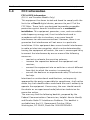
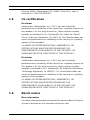
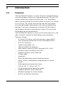
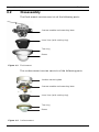
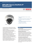
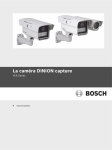
3.2
FlexiDome2X
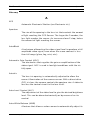
Disassembly
The flush-mount version consists of the following parts:
Camera module and mounting base
Inner liner (with sealing ring)
Trim ring
Dome
Figure 3.1 Flush-mount
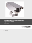
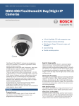
The surface-mount version consists of the following parts:
Surface mounting box
Camera module and mounting base
Inner liner (with sealing ring)
Trim ring
Dome
Figure 3.2 Surface-mount
AR18-08-B010 | v1.0 | 2009.03
Installation Manual
Bosch Security Systems
FlexiDome2X
Installation | en
17
To disassemble the unit proceed as follows:
1.
Use the special screwdriver bit to loosen the three tamperresistant screws in the trim ring (the screws remain in
place).
2.
Remove the trim ring and dome by pulling them from the
base.
3.
Remove the inner liner (with sealing ring) by pulling it off
of the base.
4.
3.3
Remove the pink protective foam.
Mounting the unit
There are several ways to mount the unit. The method of
mounting depends on the type of surface and whether other
mounting hardware, such as an electrical box, a surface box or
other accessories are used.
Note:
If the unit is to be surface mounted, then use the Surface Mount
Box (SMB). The SMB is sold as a separate item (VDA-455SMB)
or is included with the FlexiDome2X with the surface mount
option. Other mounting accessories are also sold separately.
3.3.1
Mounting tips
–
Use the mounting hole template to assist in marking the
–
Refer to the dimensions on the mounting hole template to
correct position for the camera to be mounted.
find the exact position of the screw holes and the entry
hole for the cables.
–
Partially screw in two screws for the keyholes and use
them to temporarily hang the camera while the
connections are made.
Bosch Security Systems
Installation Manual
AR18-08-B010 | v1.0 | 2009.03
18
en | Installation
3.3.2
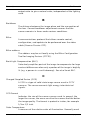
FlexiDome2X
Flush mounting
Figure 3.3
1.
2.
3.
4.
Solid surface (pre-drill three 8mm holes and fit supplied plugs)
Three screws (supplied with camera)
Integrated camera unit and base
Cables
Figure 3.4
1.
2.
3.
Flush mounting - hollow surface
Flush mounting - electrical box (4S)
Two screws (not supplied)
Integrated camera unit and base
4S electrical box
AR18-08-B010 | v1.0 | 2009.03
Installation Manual
Bosch Security Systems
FlexiDome2X
3.3.3
Installation | en
19
Surface mounting
When using the surface mounting box:
–
With a side connection, remove the cap covering the side
entrance.
With a rear connection, leave the cap in place.
–
Attach the conduit to the mounting box.
–
Release the two clips at the bottom of the watertight
connection compartment to remove it from the mounting
box.
–
Open the cover of the watertight compartment in the
mounting box by releasing the five clips.
–
Run the power and video cables through separate rubber
grommets into the watertight compartment.
–
Run the cable from the camera into the watertight
–
Make the connection inside the watertight compartment
compartment through the supplied grommet.
and clip on the cover to seal it.
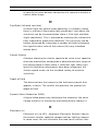
Figure 3.5
Surface mounting box VDA-455SMB
Note:
To ensure a watertight cable entry, use round cables of
between 5 and 6 mm (0.2 - 0.24 inches) for power and video
connection.
Note:
Use some silicon spray on the cable to help slide the grommets
onto it.
Bosch Security Systems
Installation Manual
AR18-08-B010 | v1.0 | 2009.03
20
en | Installation
FlexiDome2X
Figure 3.6
1.
2.
3.
4.
5.
6.
7.
Solid surface (pre-drill three 8mm holes and fit supplied plugs)
Three screws (supplied with camera)
Three screws (M5, supplied)
Integrated camera unit and base
Surface mounting box (VDA-455SMB)
Cables
Conduit
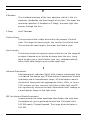
Figure 3.7
1.
2.
3.
4.
5
6.
7.
8.
Surface mounting - side connection
Surface mounting - rear connection
Solid surface (three pre-drilled 8mm holes and fit supplied plugs)
Three screws (supplied with camera)
Three screws (M5, supplied)
Integrated camera unit and base
Surface mounting box (VDA-455SMB)
Cap (remove for side-entry cables)
Conduit
Cables
AR18-08-B010 | v1.0 | 2009.03
Installation Manual
Bosch Security Systems
FlexiDome2X
Connection and set-up | en
4
Connection and set-up
4.1
Power and video connections
21
The wiring harness has a BNC connector to accept the video
coax cable (with male BNC connector) and two stripped low
voltage power wires for connection to a power connector. A
UTP adapter (VDA-455UTP) is available as an optional accessory
to allow a UTP video cable to be connected to the BNC
connector.
WARNING!
!
Before proceeding, disconnect the power from the power
supply cable. Ensure that the voltage of the unit matches the
voltage and type of the power supply being used.
The easiest way to connect the cables is as follows:
1.
Bring the building connections through the surface cable
hole so that they hang clear.
2.
Partially insert two screws into the pre-drilled holes (or
adapter plate).
3.
Using one of the keyholes, hang the mounting base of the
camera module on one screw temporarily; tilt the base
slightly to gain access to the cable connections.
4.
Connect the BNC connector of the camera module to the
video coax cable.
5.
Connect the stripped power wires (red +, brown –) to the
power supply connector.
Note
For a DC supply the polarity is important. Incorrect polarity
does not damage the camera but it will not switch on.
For an AC supply maintain a consistent wiring polarity in
multiple camera systems to help avoid potential camera video
rolling.
Bosch Security Systems
Installation Manual
AR18-08-B010 | v1.0 | 2009.03
22
en | Connection and set-up
6.
FlexiDome2X
In damp environments ensure that the connections are
sealed. (The surface mounting box and the other mounting
accessories have a sealed compartment for this purpose.)
7.
Push the connections back through the surface cable hole.
8.
Secure the mounting base of the camera module to the
surface with three screws.
AR18-08-B010 | v1.0 | 2009.03
Installation Manual
Bosch Security Systems
FlexiDome2X
4.2
Connection and set-up | en
23
Setting up the camera
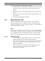
4.2.1
Camera positioning
CAUTION!
!
The Heater will be hot when in operation - Do not touch.
Always switch the heater off when working on the camera, refer
to Section 4.2.4 Heater, Page 26 and Section 5.6.2 Connections
submenu, Page 42.
To assist in setting up the camera, connect a monitor to the
miniature 2.5 mm jack socket (2). This socket provides a
composite video signal (with sync). An optional cable (code
number S1460) is available for making this connection. When
the S1460 cable is attached, there is no video available on the
BNC connector to avoid interference.
A
C
B
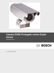
Figure 4.1
1.
2.
3.
Bosch Security Systems
Camera parts
Heater
Monitor jack socket
Thumbwheels
Installation Manual
AR18-08-B010 | v1.0 | 2009.03
24
en | Connection and set-up
4.
5.
6.
A.
B.
C.
FlexiDome2X
Navigation buttons (5)
Focal length
Focus
Pan-axis rotation
Tilt-axis rotation
Twist-axis rotation
The physical default position of the camera is that the top of
the image corresponds to the indication TOP.
CAUTION!
CCD image sensors are highly sensitive and require special care
!
for proper performance and extended lifetime. Do not expose
them to direct sunlight or bright spotlights in operating and
non-operating conditions. Avoid bright lights in the field of view
of the camera.
The camera module position can be adjusted along three axes.
When adjusting the camera position, ensure that the picture
display on the monitor is level. Set the camera to the desired
position by performing the following steps:
–
For horizontal adjustment along the pan axis (A), rotate the
camera module in the base. Do not rotate more than 360°.
–
To obtain a horizontal horizon (for tilted ceilings or
sidewall mounting), rotate the base of the lens along the
twist axis (C) to align the picture shown on the monitor.
Do not rotate more than 340°.
–
For vertical adjustment along the tilt axis (B), loosen
thumbwheels, position camera, then gently tighten
thumbwheels to secure camera. Do not rotate more than
90°.
AR18-08-B010 | v1.0 | 2009.03
Installation Manual
Bosch Security Systems
FlexiDome2X
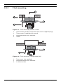
4.2.2
Connection and set-up | en
25
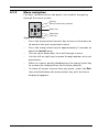
Menu navigation
Five keys, located on the side panel, are used for navigating
through the menu system.
Up key
Menu/Select key (center)
Right key
Down key
Left key
Figure 4.2
–
Navigation
Press the menu/select (center) key to access the menus or
to move to the next or previous menu.
–
Press the menu/select key for approximately 2 seconds to
open the Install menu.
–
Use the up or down keys to scroll through a menu.
–
Use the left or right keys to move through options or to set
parameters.
–
When in a menu, quickly double-press the menu/select key
to restore the selected item to its factory default.
–
To close all menus at once from any menu, select the Exit
item and hold down the menu/select key until the menu
display disappears.
Bosch Security Systems
Installation Manual
AR18-08-B010 | v1.0 | 2009.03
26
en | Connection and set-up
4.2.3
FlexiDome2X
Focal length and focus
Before adjusting the focal length or focus, place the lens
adjustment cap on the lens to ensure that the image sharpness
is the same as when the dome is in place.
1.
Connect a monitor or other display device to either the
camera’s BNC connector or to the optional cable (S1460)
on the monitor jack. (If S1460 is connected, there is no
signal on the BNC connector.)
2.
Press and hold the menu/select (center) button until the
Install menu appears.
–
The Set focus item is highlighted. Do not change this
selection as the camera is now in a special mode for
adjusting focus.
3.
To set the field of view of the varifocal lens, loosen the
focal length screw and turn the mechanism until the
required view is displayed on the monitor. (Image goes out
of focus.)
4.
Focus the image on the monitor by loosening the focus
screw and turning the mechanism until the image is in
focus.
5.
6.
Re-adjust the focal length if necessary.
Repeat these two adjustments until the desired view is in
focus.
7.
Tighten both screws.
8.
Use the navigation buttons to move to Exit and press the
center button until the menu disappears.
9.
Remove the lens adjustment cap from the lens and
disconnect the monitor.
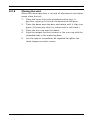
4.2.4
Heater
When using the camera at low temperatures, set the heater
setting to Auto in the Install menu. The heater turns on at
ambient temperatures below 0°C (+32°F).
AR18-08-B010 | v1.0 | 2009.03
Installation Manual
Bosch Security Systems
FlexiDome2X
4.2.5
Connection and set-up | en
27
Closing the unit
When the camera position is set and all adjustments have been
made, close the unit.
1.
Place the inner liner (with attached sealing ring) in
position, aligning its fin with the bracket on the base.
2.
Place the dome onto the base and rotate until it clips into
place. (If necessary clean its surface with a soft cloth.)
3.
4.
Place the trim ring over the dome.
Align the tamper-resistant screws in the trim ring with the
threaded ends in the mounting base.
5.
Use the special screwdriver bit supplied to tighten the
three tamper-resistant screws.
Bosch Security Systems
Installation Manual
AR18-08-B010 | v1.0 | 2009.03
FlexiDome2X
5
Configuration | en
29
Configuration
The camera normally provides an optimal picture without the
need for further adjustments. There are six pre-defined modes
with settings to make configuration easier. Advanced set-up
options are available in a menu system for getting the best
results under special circumstances.
The camera implements your changes immediately so that
before and after settings are easily compared.
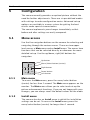
5.1
Menu access
Use the five navigation buttons on the camera for selecting and
navigating through the various menus. There are two upper
level menus: a Main menu and an Install menu. The menus have
functions that can be selected directly or submenus for more
detailed set-up. Use the up/down, right/left buttons for
navigation.
Up button
Menu/Select button (center)
Right button
Down button
Left button
5.1.1
Main menu
To access the Main menu, press the menu/select button
(center) for less than 1 second. The Main menu appears on the
monitor. The Main menu allows you to select and set-up the
picture enhancement functions. If you are not happy with your
changes, you can always recall the default values for the mode.
5.1.2
Install menu
The camera also has an Install menu in which the installation
settings can be set. To access the Install menu, press the
menu/select button (center) for longer than 1 second.
Bosch Security Systems
Installation Manual
AR18-08-B010 | v1.0 | 2009.03
30
en | Configuration
5.2
FlexiDome2X
Pre-defined modes
There are six pre-defined modes with settings to make
configuration easier. You can select one of the six pre-defined
modes in the Install/Mode submenu. The modes are defined as
follows:
1.
24-hour
Default installation mode to provide stable pictures over a
24-hour period. These settings are optimized for out-ofthe-box installation.
2.
Traffic
Capture high-speed objects using default shutter in
variable lighting conditions.
3.
Low light
Provide extra enhancement, such as AGC and SensUp to
make usable pictures in low-light conditions.
4.
Smart BLC
Settings optimized to capture details in high contrast and
extremely bright-dark conditions.
5.
Low noise
Enhancements are set to reduce picture noise. Useful for
conditional refresh DVR and IP storage systems because
reducing noise reduces the amount of storage required.
6.
Analog systems
Use this mode if the camera is connected to a purely
analog system (e.g. matrix switcher with VCR) or to a CRT
monitor. Useful mode for evaluating/demonstrating the
camera when it is directly connected to a CRT monitor.
AR18-08-B010 | v1.0 | 2009.03
Installation Manual
Bosch Security Systems
FlexiDome2X
5.3
Configuration | en
31
Day/Night switching
The camera is equipped with a motorized IR filter. The
mechanical IR filter can be removed in low-light or IR
illuminated applications by software configuration settings.
If Auto switching mode is selected, the camera automatically
switches the filter depending on the observed light level. The
switching level is programmable. In Auto switching mode the
camera prioritizes motion (the camera gives sharp images
without motion blur as long as the light level permits) or color
(the camera gives color pictures as long as the light level
permits). The camera recognizes IR illuminated scenes to
prevent unwanted switching to color mode.
There are four different methods of controlling the IR filter:
–
5.4
via an alarm input,
–
via Bilinx communication,
–
automatically, based on the observed light levels, or
–
as part of the programmable mode profile.
Camera control communication (Bilinx)
This camera is equipped with a coaxial communications
transceiver (also refered to as Bilinx). In combination with VPCFGSFT, the camera setting can be changed from any point
along the coaxial cable. All menus can be accessed remotely
giving full control of the camera. With this method of
communication it is also possible to disable the local keys on
the camera.
To avoid loss of communication on an installed camera, the
Communication On/Off selection is not available while using
remote control. This function can only be accessed with the
camera buttons. Bilinx communications can only be disabled
using the buttons on the camera.
Disabled camera buttons
When the Bilinx communications link is active, the buttons on
the camera are disabled.
Bosch Security Systems
Installation Manual
AR18-08-B010 | v1.0 | 2009.03
32
en | Configuration
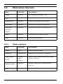
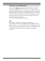
5.5
FlexiDome2X
Main menu structure
Item
Selection
Description
Mode
Submenu
Sets up operating modes 1 to 6
ALC
Submenu
Video level control
Shutter/AGC
Submenu
Shutter and automatic gain control
Day/Night
Submenu
Day/Night for color/mono operation
Enhance /
Submenu
Picture enhancement and performance
Color
Submenu
White balance and color rendition
VMD
Submenu
Video motion detection
Dynamic
Engine
5.5.1
Mode submenu
Item
Selection
Description
Mode
1 to 6
Selects operating mode.
Mode ID
Alphanumeric
Mode name (11 characters maximum)
Copy active
Available
Copies current mode settings to the mode
mode
mode
number selected.
numbers
Default mode
Submenu
Restores camera to the factory default
settings.
EXIT
AR18-08-B010 | v1.0 | 2009.03
Returns to main menu.
Installation Manual
Bosch Security Systems
FlexiDome2X
Configuration | en
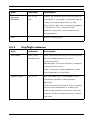
5.5.2
ALC submenu
Item
Selection
Description
ALC level
-15 to +15
Selects the range within which the ALC will
33
operate. A positive value is more useful for
low-light conditions; a negative value is more
useful for very bright conditions.
Some ALC adjustment may improve scene
content when Smart/BLC is enabled.
Peak/average
-15 to +15
Adjusts the balance between peak and
average video control. A negative value gives
more priority to average light levels; a positive
value gives more priority to peak light levels.
Video iris lens: choose an average level for
best results (peak settings may cause
oscillations).
ALC speed
Slow, medium,
Adjusts the speed of the video level control
fast
loop. For most scenes it should remain at the
default value.
DVR/IP
Encoder
On, Off
On - The camera output is optimized for
connection to a DVR or IP encoder to
compensate for compression methods.
Off - The camera output is optimized for
connection to an analog system (matrix
switcher or monitor.
EXIT
Bosch Security Systems
Returns to main menu.
Installation Manual
AR18-08-B010 | v1.0 | 2009.03
34
en | Configuration
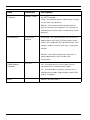
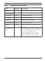
5.5.3
FlexiDome2X
Shutter/AGC submenu
Item
Selection
Description
Shutter
AES, FL, Fixed
AES (auto-shutter) - the camera automatically
sets the optimum shutter speed.
FL - flickerless mode avoids interference from
light sources.
FIXED - allows a user defined shutter speed.
Default (AES)
1/50 (PAL),
In AES mode, the camera tries to maintain the
shutter
1/60 (NTSC)
selected shutter speed as long as the light
or
1/100, 1/120,
level of the scene is high enough.
Fixed shutter
1/250,
In Fixed mode, selects shutter speed.
1/500,
1/1000,
1/2000,
1/5000,
1/10K
Actual shutter
Displays the actual shutter value from the
camera to help compare lighting levels and
optimum shutter speed during set-up.
Gain control
On, Fixed
On - the camera automatically sets the gain to
the lowest possible value needed to maintain
a good picture.
Fixed - sets Fixed AGC value.
Maximum AGC
0 to 30 dB
Selects the maximum value the gain can have
or
during AGC operation.
Fixed AGC
Selects the gain setting for Fixed gain
operation (0 is no gain).
Actual AGC
Displays the actual AGC value from the
camera to help compare gain level with
lighting levels and picture performance.
AR18-08-B010 | v1.0 | 2009.03
Installation Manual
Bosch Security Systems
FlexiDome2X
Configuration | en
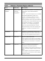
35
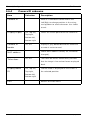
Item
Selection
Description
SensUp
Off, 2x, 3x, …,
Selects the factor by which the sensitivity of
Dynamic
10x
the camera is increased. It is dynamic and so
is only active when light levels are low.
When active, some noise or spots may appear
in the picture. This is normal camera
behavior. It may also cause motion blur on
moving objects.
EXIT
5.5.4
Returns to main menu.
Day/Night submenu
Item
Selection
Description
Day/Night
Auto, Color,
Auto - the camera switches the IR cut-off filter
Monochrome
on and off depending on the scene
illumination level.
Monochrome - the IR cut-off filter is removed,
giving full IR sensitivity.
Color - the camera always produces a color
signal regardless of light levels.
Switch level
-15 to +15
Sets the video level in Auto mode at which
the camera switches to monochrome
operation.
A low (negative) value means that the camera
switches to monochrome at a lower light
level. A high (positive) value means that the
camera switches to monochrome at a higher
light level.
Bosch Security Systems
Installation Manual
AR18-08-B010 | v1.0 | 2009.03
36
en | Configuration
FlexiDome2X
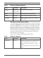
Item
Selection
Description
Priority
Motion, Color
In AUTO mode:
Color - the camera gives a color image as long
as the light level permits.
Motion - the camera avoids motion blur as
long as the light level permits (it switches to
monochrome earlier than it would with Color
priority).
IR contrast
Enhanced,
Enhanced - the camera optimizes contrast in
Normal
applications with high IR illumination levels.
Select this mode for IR (730 to 940 nm) light
sources and for scenes with grass and green
foliage.
Normal - the camera optimizes contrast in
mono applications with visible light
illumination.
Color burst
On, Off
(mono)
Off - the color burst in the video signal is
switched Off in monochrome mode.
On - the color burst remains active even in
monochrome mode (required by some DVRs
and IP encoders).
EXIT
AR18-08-B010 | v1.0 | 2009.03
Returns to main menu.
Installation Manual
Bosch Security Systems
FlexiDome2X
5.5.5
Configuration | en
37
Enhance / Dynamic Engine submenu
Item
Selection
Description
Dynamic
Off, XF-DYN,
Off: - turns off all automatic scene detail and
Engine
2X-DYN,
enhancments (only recommended for
SmartBLC
testing).
XF-DYN: - extra internal processing is enabled
for low-light applications (traffic, etc.).
2X-DYN: - 2X-Dynamic adds dual sensor
exposure to the XF-DYN features. In harsh
lighting conditions pixels from each exposure
are mixed to give a more detailed image (use
2X-DYN when SmartBLC is not required).
SmartBLC: - BLC window and weighting
factor are automatically defined. Camera
dynamically adjusts these for changing light
conditions. Includes all the benefits of 2XDYN.
Autoblack
On, Off
Autoblack On automatically increases the
visibility of details even when scene contrast
is less than full-range due to mist, fog, etc.
Black level
-50 to +50
Adjusts the black offset level.
A low (negative) value makes the level darker.
A high (positive) value makes the level lighter
and may bring out more detail in the darker
areas.
Sharpness
-15 to +15
Adjusts the sharpness of the picture. 0
corresponds to the default position.
A low (negative) value makes the picture less
sharp. Increasing sharpness brings out more
detail.
Extra sharpness can enhance the details of
license plates, facial features and the edges
of certain surfaces.
Bosch Security Systems
Installation Manual
AR18-08-B010 | v1.0 | 2009.03
38
en | Configuration
FlexiDome2X
Item
Selection
Description
Dynamic noise
Auto, Off
In AUTO mode the camera automatically
reduction
reduces the noise in the picture.
This may cause some motion blur on
exceptionally fast moving objects immediately
in front of the camera. This can be corrected
by widening the field of view or selecting Off.
Peak White
On, Off
Use Peak White Invert to reduce glare from
Invert
the CRT/LCD display.
Use in ANPR/LPR applications to reduce
headlight glare. (Test on-site to ensure that it
does benefit the application and is not
distracting for operators of the security
system.)
EXIT
5.5.6
Returns to main menu.
Color submenu
Item
Selection
Description
White balance
ATW,
ATW - Auto tracking white balance allows the
AWBhold,
camera to constantly adjust for optimal color
Manual
reproduction.
AWBhold - Puts the ATW on hold and saves
the color settings.
Manual - the Red, Green, and Blue gain can be
manually set to a desired position.
Speed
Red gain
Fast, Medium,
Adjusts the speed of the white balance
Slow
control loop.
-5 to +5
ATW and AWBhold - adjusts the Red gain to
-50 to +50
Manual - adjusts the Red gain.
optimize the white point.
AR18-08-B010 | v1.0 | 2009.03
Installation Manual
Bosch Security Systems
FlexiDome2X
Configuration | en
Item
Selection
Description
Blue gain
-5 to +5
ATW and AWBhold - adjusts the B gain to
39
optimize the white point.
-50 to +50
Manual - adjusts the Blue gain.
Green gain
-50 to +50
Manual - adjusts the Green gain.
Saturation
-15 to +5
Adjusts the color saturation. -15 gives a
monochrome image.
EXIT
5.5.7
Returns to main menu.
VMD submenu
Item
Selection
Description
VMD
Off, Silent,
Off - Video Motion Detection (VMD) is off.
OSD
Silent - video motion generates silent alarm.
OSD - video motion generates on-screen text
message alarm.
VMD area
Submenu
Select to enter the area set-up menu to define
the detection area.
Motion
Indicates the peak of measured motion in the
indicator
selected area. Press either the right, left or
center navigation button to reset.
VMD
Sets the sensitivity for motion to the desired
sensitivity
level. The longer the white bar, the more
motion is required to acitvate the VMD alarm.
Motion above this level triggers alarm.
OSD alarm
Alphanumeric
Text for on-screen display alarm (16
text
characters maximum).
EXIT
Returns to main menu.
Bosch Security Systems
Installation Manual
AR18-08-B010 | v1.0 | 2009.03
40
en | Configuration
FlexiDome2X
Selecting an area for VMD masking
To set-up an area for VMD masking, access the area menu by
selecting the VMD Area option from the VMD menu. Upon
entering the Area menu, the current area is displayed with the
upper left corner flashing. The flashing corner of the image can
be moved with the Up, Down, Left, Right arrow keys. Pressing
the Select key moves the flashing cursor to the opposite corner,
which can now be moved. Pressing Select again freezes the
area and exits the area menu.
There is one programmable VMD area.
Note:
When VMD is enabled, normal light fluctuations or
environmental factors can contribute to false-positive alarms.
Because of this, it is recommended that you do not connect the
VMD-triggered alarm output of the camera to a monitored alarm
system as the false-positive alarms may be considered a
nuisance.
AR18-08-B010 | v1.0 | 2009.03
Installation Manual
Bosch Security Systems
FlexiDome2X
5.6
Configuration | en
41
Install menu structure
Item
Selection
Description
Language
Submenu
Select on-screen display (OSD) language
Synchronization
Submenu
Sets synchronization parameters.
Connections
Submenu
Connection parameters
Test signals
Submenu
Test patterns and texts
Camera ID
Submenu
Select to access ID submenu
Privacy masking
Submenu
Sets up a masking area
Default ALL
Submenu
Returns all settings for all modes to factory
defaults
Set backfocus
Select to close the Install menu and open the
now
lens wizard. Adjust the focus as described in
Section 4.2.3 Focal length and focus.
When finished adjusting, press the Up or
Down navigation button to exit the lens
wizard and open the Install menu again.
Bosch Security Systems
Installation Manual
AR18-08-B010 | v1.0 | 2009.03
42
en | Configuration
5.6.1
FlexiDome2X
Language submenu
Item
Selection
Description
Language
English
Displays the menus on the OSD in the
Spanish
choosen language.
French
German
Portuguese
Polish
Italian
Dutch
Russian
EXIT
5.6.2
Returns to Install menu.
Connections submenu
Item
Selection
Notch filter
On, Off
Description
Switches notch filter on or off. The notch
filter can remove a Moiré pattern or color
artifacts caused by closely spaced vertical
lines or objects (e.g. vertical security bars
over windows).
Heater
Off, Auto
Select Auto to enable the thermostatically
controlled heater function. The heater turns
on at approximately 0 °C (+32 °F).
Bilinx Comms.
On, Off
EXIT
AR18-08-B010 | v1.0 | 2009.03
If Off, Bilinx communications is disabled.
Returns to Install menu.
Installation Manual
Bosch Security Systems
FlexiDome2X
5.6.3
Configuration | en
43
Test signal submenu
Item
Selection
Description
Show camera
Off, On
Select On to overlay the camera ID on the
ID
Test pattern
video test signal.
Color bars
Select the desired test pattern to help
100%,
installation and fault-finding.
Grayscale 11step,
Sawtooth 2H,
Checker
board,
Cross hatch,
UV plane
EXIT
Bosch Security Systems
Returns to Install menu.
Installation Manual
AR18-08-B010 | v1.0 | 2009.03
44
en | Configuration
5.6.4
FlexiDome2X
Camera ID submenu
Item
Selection
Camera ID
Description
Enter a 17-character camera name. Use
Left/Right to change position in the string;
use up/down to select character. Use Select
to exit.
Display ID pos.
Off, Top left,
Select the screen position of the camera ID.
Top right,
Bottom left,
Bottom right
Camera ID
On, Off
Displays a grey border behind the camera ID
border
to make it easier to read.
MAC address
Shows MAC address (factory set, cannot be
changed).
Ticker bars
On, Off
The ticker bar moves continuously to show
that the image is live and not frozen or played
back.
Display mode
Off, Top left,
Camera mode is displayed on the screen in
ID
Top right,
the selected position.
Bottom left,
Bottom right
EXIT
AR18-08-B010 | v1.0 | 2009.03
Returns to Install menu.
Installation Manual
Bosch Security Systems
FlexiDome2X
5.6.5
Configuration | en
45
Privacy masking submenu
Item
Selection
Description
Pattern
Black, Grey,
Selects pattern for all masks.
White, Noise
Mask
1, 2, 3, 4
Four different areas can be masked.
Active
On, Off
Turns each of the four masks on or off.
Window
Submenu
Select to open a window in which to define
the mask area.
Selecting an area for privacy masking
To set-up an area for privacy masking, access the area menu by
selecting the Area option from the privacy masking menu. Upon
entering the Area menu, the current area is displayed with the
upper left corner flashing. The flashing corner of the image can
be moved with the Up, Down, Left, Right arrow keys. Pressing
the Select key moves the flashing cursor to the opposite corner,
which can now be moved. Pressing Select again freezes the
area and exits the area menu.
There are four programmable privacy mask areas.
5.6.6
Defaults submenu
Item
Selection
Description
Restore All
No, Yes
Restores all settings of the six modes to their
default (factory) values. Select YES then
press the Menu/Select button to restore all
values.
When completed the message RESTORED! is
shown.
Bosch Security Systems
Installation Manual
AR18-08-B010 | v1.0 | 2009.03
FlexiDome2X
Troubleshooting | en
6
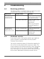
Troubleshooting
6.1
Resolving problems
47
The following table is intended to help you identify the causes
of malfunctions and correct them when possible.
Malfunction
Possible causes
Solution
No image
Defective camera.
Connect a local monitor
transmission to
to the camera and check
remote location.
the camera function.
Faulty cable connections. Check all cables, plugs,
contacts and
connections.
When using DC power
ensure that polarity is
correct.
No connection
The unit's configuration.
Check all configuration
established, no
parameters.
image transmission. Faulty installation.
Check all cables, plugs,
contacts and
connections.
6.2
Customer service
If you cannot resolve a fault, please contact your supplier or
system integrator, or contact Bosch Security Systems
Customer Service directly.
The Installer should write down all information regarding the
unit so that it can be referenced for warranty or repair. The
version numbers of the firmware and other status information
can be seen when the unit starts or by opening the Install
menu. Note down this information and the information found
on the camera label before contacting customer service.
Bosch Security Systems
Installation Manual
AR18-08-B010 | v1.0 | 2009.03
FlexiDome2X
Maintenance | en
7
Maintenance
7.1
Repairs
49
CAUTION!
Never open the casing of the camera. The unit does not contain
!
any user serviceable parts. Ensure that all maintenance or
repair work is performed only by qualified personnel (electrical
engineering or network technology specialists). If in doubt,
contact your dealer's technical service center.
7.1.1
Transfer and disposal
The camera should only be passed-on together with this
installation guide. The unit contains environmentally hazardous
materials that must be disposed of according to law. Defective
or superfluous devices and parts should be disposed of
professionally or taken to your local collection point for
hazardous materials.
Bosch Security Systems
Installation Manual
AR18-08-B010 | v1.0 | 2009.03
FlexiDome2X
Technical Data | en
8
Technical Data
8.1
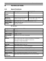
Specifications
Type number
VDN-498V03
VDN-498V09
Lens focal
2.8 to 10 mm
9 to 22 mm
F-stop
F1.2
F1.4
Minimum
0.28 (0.027) lx (fc) 30IRE
0.32 (0.03) lx (fc) 30IRE
Illumination
0.099 (0.0092) mono
0.11 (0.01) mono
Active pixels
752 x 582 (PAL - 11), 768 x 494 (NTSC - 21)
Rated supply
24 VAC (±10%) or
voltage
+12 VDC (±10%)
51
length
All versions
Imager
1/3-inch interline CCD
Resolution
540 TVL
SNR
> 50 dB
Video output
1 Vpp, 75 Ohm
Synchroniza-
Internal or Line Lock selectable
tion
Shutter
AES (1/60 [1/50] to 1/10000) customer selectable
AES (1/60 [1/50] to 1/15000) automatic
flickerless, fixed selectable
Day/Night
Color, Mono, Auto
Sens Up
Adjustable from Off to 10x
AGC
AGC On or Off (0 - 30 dB) selectable
Dynamic engine XF-Dynamic, 2X-Dynamic, SmartBLC
DNR
Automatic noise filtering On/Off selectable
Sharpness
Sharpness enhancement level selectable
White Balance
ATW, AWBhold and manual (2500 to 10000K)
Color
Adjustable from monochrome (0%) to 133% color
saturation
Bosch Security Systems
Installation Manual
AR18-08-B010 | v1.0 | 2009.03
52
en | Technical Data
FlexiDome2X
ALC lens
DC iris
Test pattern
Color bars 100%, Greyscale 11-step, Sawtooth 2H,
generator
Checker board, Cross hatch, UV plane
Video Motion
One area, fully programmable
Detection
(VMD)
Privacy
Four independent areas, fully programmable; black,
Masking
white, grey, noise
Communication Two-way Bilinx (bi-directional)
Languages
English, Spanish, French, German, Portuguese, Polish,
(OSD)
Italian, Dutch, Russian
Modes
6 programmable (preset) modes: 24-hour, Traffic, Lowlight, SmartBLC, Low noise, Analogue systems
Peak White
Suppresses highlights in scenes
Invert
Misc.
Notch filter, Actual AGC, Actual shutter, IR contrast
Power
12 VDC 400 mA
consumption
24 VDC 330 mA
Weight
550 g (1.21 lb)
Operating
-30 °C to +55 °C (-22 °F to +131 °F)
temperature
(-50 °C [-58 °F] with heater enabled)
Controls
OSD with softkey operation
AR18-08-B010 | v1.0 | 2009.03
Installation Manual
Bosch Security Systems
FlexiDome2X
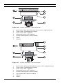
8.1.1
Technical Data | en
53
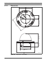
Dimensions
57.6 (2.27)
1
12
66.5 (2.62)
33.3 (1.31)
57.6 (2.27)
39.5 (1.56)
85 (3.35)
7)
.7
(4
95 (3.7)
158 (6.22)
Figure 8.1
Bosch Security Systems
mm (in)
Dimensions - Flush-mount
Installation Manual
AR18-08-B010 | v1.0 | 2009.03
54
en | Technical Data
FlexiDome2X
53.3 (2.1)
35 (1.38)
30.8 (1.21)
53.3 (2.1)
4.77)
130.5 (5.14)
121 (
158 (6.22)
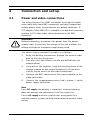
Figure 8.2
AR18-08-B010 | v1.0 | 2009.03
mm (in)
Dimensions - Surface-mount
Installation Manual
Bosch Security Systems
FlexiDome2X
8.1.2
Technical Data | en
55
Accessories
–
BNC to UTP transceiver
–
Surface Mount Box (SMB)
–
Pendant wall mount
–
Pendant ceiling mount
–
Corner mount
–
Bilinx communication interface box and software
Contact a Bosch representative in your area for the latest
available accessories or visit our website at
www.boschsecurity.com
Bosch Security Systems
Installation Manual
AR18-08-B010 | v1.0 | 2009.03
FlexiDome2X
| en
57
Glossary
A
AES
Automatic Electronic Shutter (see Electronic iris).
Aperture
The size of the opening in the lens iris that controls the amount
of light reaching the CCD Sensor. The larger the F-number, the
less light reaches the sensor. An increase of one F-stop, halves
the amount of light reaching the sensor.
AutoBlack
A technique of boosting the video signal level to produce a full
amplitude video signal, even when the scene contrast is less
than full range (glare, fog, mist, etc.).
Automatic Gain Control (AGC)
The electronics that regulate the gain or amplification of the
video signal. AGC is used in low-light conditions with the iris
fully open.
AutoIris
The lens iris opening is automatically adjusted to allow the
correct illumination of the camera sensor. With a direct drive
(DC) iris lens, the camera controls the aperture size. A video iris
lens has the control circuit in the lens itself.
Auto Level Control (ALC)
The adjustment of the video level to give the desired brightness
level. This can be done electronically or by means of an iris
control.
Auto White Balance (AWB)
A feature that allows a color camera to automatically adjust its
Bosch Security Systems
Installation Manual
AR18-08-B010 | v1.0 | 2009.03
58
en |
FlexiDome2X
output color to give a natural color, independent of the lighting
used.
B
Backfocus
The distance between the image plane and the rear portion of
the lens. Correct backfocus adjustment ensures that the
camera remains in focus under various conditions.
Bilinx
A communications protocol that allows remote control,
configuration, and updates to be performed over the video
cable (Coax or Passive UTP).
Bilinx address
The address may be set locally using the Bilinx Configuration
Tool for Imaging Devices (CTFID).
Back Light Compensation (BLC)
Selectively amplifies parts of the image to compensate for large
contrast differences when only a portion of the image is brightly
lit (e.g. a person in a sunlit doorway). See also Smart BLC.
C
Charged Coupled Device (CCD)
A CCD is a type of solid state image sensor used in CCTV
cameras. The sensor converts light energy into electrical
signals.
CCD Format
Indicates the size of the camera sensor used. In general, the
larger the sensor, the more sensitive the camera and the better
the image quality. The format is quoted in inches, for example
1/3 or 1/2 inch.
Color Temperature
A measure of the relative color of illumination. Generally used
AR18-08-B010 | v1.0 | 2009.03
Installation Manual
Bosch Security Systems
FlexiDome2X
| en
59
to specify the color balance correction of a camera to achieve a
natural color image.
D
Day/Night (infrared sensitive)
A camera that has normal color operation in situations where
there is sufficient illumination (day conditions), but where the
sensitivity can be increased when there is little light available
(night conditions). This is achieved by removing the infrared cut
filter required for good color rendition. The sensitivity can be
further enhanced by integrating a number of fields to improve
the signal-to-noise ratio of the camera (this may introduce
motion blur).
Default Shutter
A feature allowing the shutter speed to be set to a fast speed to
eliminate motion blur and provide a detailed and clear image of
fast-moving objects while there is sufficient light. When light
levels fall and other adjustments have been exhausted, the
shutter speed reverts to the standard setting to maintain
sensitivity.
Depth of Field
The distance from the nearest to the furthermost point that
appears in focus. The smaller the aperture, the greater the
depth of field.
Dynamic Noise Reduction (DNR)
A digital video processing technique that measures the noise
(image artifacts) in the picture and automatically reduces it.
E
Electronic iris
Electronic iris (or AES - Automatic Electronic Shutter) adjusts
the camera shutter speed to compensate for lighting changes.
In some cases this can eliminate the need for an autoiris lens.
Bosch Security Systems
Installation Manual
AR18-08-B010 | v1.0 | 2009.03
60
en |
FlexiDome2X
F
F-Number
The standard measure of the lens aperture, which is the iris
diameter, divided by the focal length of the lens. The lower the
maximum aperture (F-Number or F-Stop), the more light that
passes through the lens.
F-Stop
See F-Number
Field of View
The measure of the visible area within the camera’s field of
view. The larger the focal length, the smaller the field of view.
The smaller the focal length, the wider the field of view.
Focal Length
The distance from the optical center of the lens to the image of
an object located at an infinite distance from the lens. Long
focal lengths give a small field of view (e.g. telephoto effect),
while short focal lengths give a wide angle view.
I
Infrared Illumination
Electromagnetic radiation (light) with a longer wavelength than
is visible to the human eye. IR illumination is prominent at dusk
and dawn and in incandescent lamps. IR illuminators come in
the form of lamps with the appropriate filters, LEDs, or lasers.
CCD sensors are less sensitive to IR than visible light, but IR
can significantly increase the total illumination level, leading to
a much better image at low light levels.
IRE (Institute of Radio Engineers)
A measurement of video amplitude that divides the area from
the bottom of sync to peak white level into 140 equal units 140 IRE equals 1V peak-to-peak. The range of active video is
100 IRE.
AR18-08-B010 | v1.0 | 2009.03
Installation Manual
Bosch Security Systems
FlexiDome2X
| en
61
L
Lens wizard
The lens wizard is used when setting the backfocus. It opens
the iris fully while maintaining the correct video level using AES.
Lux
The international (SI) unit of measurement of the intensity of
light. It is equal to the illumination of a surface one meter away
from a single candle.
O
OSD
On-screen Display: Menus are shown on the display monitor.
P
Privacy Masking
The ability to mask out a specific area to prevent it from being
viewed in order to comply with privacy laws and particular site
requirements.
PWIE
Peak White Inverse Engine: White highlights are automatically
turned black to reduce bright spots. Useful in traffic and car
park applications.
R
Region of Interest
A specific area within a field of view, used by the motion
detection algorithm to identify motion.
Resolution
The measure of the fine detail that can be seen in an image. For
analog systems this is typically measured in horizontal
Television Lines or TVL. The higher the TVL rating, the higher
the resolution.
Bosch Security Systems
Installation Manual
AR18-08-B010 | v1.0 | 2009.03
62
en |
FlexiDome2X
S
Saturation
The amplitude of the chrominance signal affecting the vividness
of the color.
Sensitivity
A measure of the amount of light required to provide a standard
video signal. Sensitivity values are stated in lux (see Lux).
SensUp (sensitivity up)
Increases camera sensitivity by increasing the integration time
on the CCD (lowering shutter time from 1/50 s to 1/5 s in PAL
or 1/60 s to 1/6 s in NTSC). This is accomplished by integrating
the signal from a number of consecutive video fields to reduce
signal noise.
Signal-to-noise ratio
The ratio between a useful video signal and unwanted noise
measured in dB.
Smart BLC (Back Light Compensation)
Smart back-light compensation allows the camera to
automatically compensate for bright areas of a high contrast
scene without having to define a window or area.
U
UTP (Unshielded Twisted Pair)
A variant of twisted pair cabling, UTP cable is not surrounded
by any shielding. The wires in a twisted pair cable are twisted
around each other to minimize interference from the other
twisted pairs in the cable. UTP is the primary wire type for
telephone usage and the most commonly used type of
networking cable.
AR18-08-B010 | v1.0 | 2009.03
Installation Manual
Bosch Security Systems
FlexiDome2X
| en
63
V
VMD
Video Motion Detection: An algorithm for motion detection in
which the camera compares the current image with a reference
image and counts the number of pixels that have changed
between the two images. An alarm is generated when the
number of pixel changes exceeds a user-configured threshold.
W
WDR (Wide Dynamic Range)
A camera’s dynamic range is the difference between the
minimum and maximum acceptable signal levels. A scene with
both very low and very high illumination levels requires a
camera with a wide dynamic range to handle it correctly and
produce a useful image.
Bosch Security Systems
Installation Manual
AR18-08-B010 | v1.0 | 2009.03
Bosch Security Systems
www.boschsecurity.com
© Bosch Security Systems, 2009