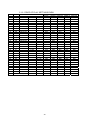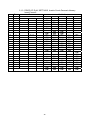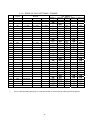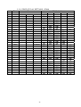
1
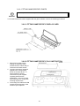
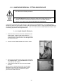
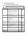
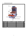
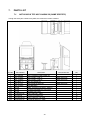
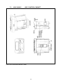
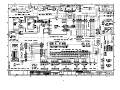
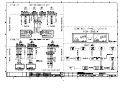
420-NOT-COM
REV 0
SERVICE MANUAL
Before using this product, read this SERVICE MANUAL carefully to understand the contents stated herein.
After reading this manual, be sure to keep it available nearby the product or somewhere convenient in order
to be able to refer to it whenever necessary.
Manufactured in the UK by
SAFETY WARNINGS
i
ii
iii
iv
v
vi
vii
viii
ix
x
xi
xii
xiii
xiv
xv
xvi
xvii
xviii
xix
xx
xxi
xxii
xxiii
xxiv
xxv
xxvi
xxvii
xxviii
xxix
xxx
xxxi
xxxii
xxxiii
xxxiv
xxxv
xxxvi
xxxvii
xxxviii
xxxix
xl
xli
xlii
xliii
xliv
xlv
xlvi
xlvii
xlviii
xlix
l
li
lii
liii
liv
lv
lvi
lvii
lviii
lix
lx
lxi
lxii
lxiii
lxiv
lxv
lxvi
lxvii
lxviii
lxix
lxx
CONTENTS
1.
BEFORE USING THIS PRODUCT ....................................................................................................................... 3
1.1.
INSPECTIONS IMMEDIATELY AFTER TRANSPORTING THE PRODUCT TO THE LOCATION ................... 4
2.
INTRODUCTION TO THIS SERVICE MANUAL ................................................................................................... 6
3.
INSTALLATION AND SERVICE INSTRUCTIONS ................................................................................................ 7
3.1.
HANDLING AND INSTALLATION PRECAUTIONS .......................................................................................... 7
3.2.
COIN HANDLING.............................................................................................................................................. 7
3.3.
NAME OF PARTS ............................................................................................................................................. 8
3.4.
ACCESSORIES ................................................................................................................................................ 9
3.5.
RETURNING THE GAME BOARD.................................................................................................................. 10
3.6.
ASSEMBLY INSTRUCTIONS ......................................................................................................................... 11
3.6.1.
INSTALLING THE BILLBOARD .............................................................................................................. 12
3.6.2.
CONNECTING SEAT AND CONTROL CABINET ASSEMBLIES ........................................................... 13
3.6.3.
CONNECTING CONTROL TO MONITOR CABINET ASSEMBLIES ...................................................... 14
3.6.4.
SECURING IN PLACE (LEG ADJUSTER ADJUSTMENT) ..................................................................... 15
3.6.5.
COIN HANDLING INSTALLATION.......................................................................................................... 16
3.6.5.1.
WIRING CONNECTIONS. .............................................................................................................. 17
3.6.6.
FITTING GAME SPECIFIC PARTS......................................................................................................... 18
3.6.6.1.
FITTING GAME SPECIFIC DISPLAY CARD .................................................................................. 18
3.6.6.2.
FITTING GAME SPECIFIC PLAY INSTRUCTION .......................................................................... 18
3.6.7.
CONNECTION TO THE POWER SUPPLY............................................................................................. 19
3.7.
MOVING THE MACHINE ................................................................................................................................ 20
3.8.
FUSES ............................................................................................................................................................ 21
3.9.
REPLACEMENT OF FLUORESCENT LAMP ................................................................................................. 22
3.9.1.
FLUORESCENT LAMP REPLACEMENT ............................................................................................... 22
3.10.
TROUBLESHOOTING ................................................................................................................................ 23
3.11.
GAME BOARD REMOVAL / FITTING NEW ROM CASE ........................................................................... 24
3.11.1.
GAME BOARD REMOVAL.................................................................................................................. 24
3.11.2.
FITTING NEW ROM CASE ................................................................................................................. 25
3.11.3.
GD ROM Unit ...................................................................................................................................... 25
3.12.
DEGAUSSING THE MONITOR................................................................................................................... 26
3.13.
PERIODIC CHECK AND INSPECTION ...................................................................................................... 27
3.13.1.
CLEANING THE CABINET SURFACES ............................................................................................. 27
4.
MAINTENANCE INSTRUCTIONS....................................................................................................................... 28
4.1.
EXPLANATION OF TEST AND DATA DISPLAY ............................................................................................ 28
4.1.1.
VTS ASSEMBLY ..................................................................................................................................... 29
4.1.2.
TEST MODE............................................................................................................................................ 30
5.
COIN MECH INSTALLATION AND CREDIT BOARD SET UP ........................................................................... 31
5.1.1.
PRICE OF PLAY SETTINGS UK............................................................................................................. 33
5.1.2.
PRICE OF PLAY SETTINGS EURO ....................................................................................................... 34
5.1.3.
PRICE OF PLAY SETTINGS Austria-Czech-Denmark-Norway-Israel-France2..................................... 35
5.1.4.
PRICE OF PLAY SETTINGS - BELGIUM ............................................................................................... 36
5.1.5.
PRICE OF PLAY SETTINGS - FRANCE................................................................................................. 37
5.1.6.
PRICE OF PLAY SETTINGS - ITALY ..................................................................................................... 38
5.1.7.
PRICE OF PLAY SETTINGS - PORTUGAL............................................................................................ 39
5.1.8.
PRICE OF PLAY SETTINGS - NETHERLANDS..................................................................................... 40
5.1.9.
PRICE OF PLAY SETTINGS - SPAIN..................................................................................................... 41
6.
DESIGN RELATED PARTS ................................................................................................................................ 42
7.
PARTS LIST........................................................................................................................................................ 43
7.1.
NOT-0000*UK TOP ASSY NAOMI 38 (GAME SPECIFIC) ............................................................................. 43
7.2.
NOT-0000UK TOP ASSY.............................................................................................................................. 44
7.3.
NOK-1000UK
ASSY CONTROL CABINET ............................................................................................ 45
7.4.
NOK-1200UK
ASSY AC UNIT................................................................................................................ 47
7.5.
NOK-1300UK
ASSY CONTROL PANEL................................................................................................ 48
7.6.
NOK-13*0UK ASSY PANEL 1L*B *P ............................................................................................................. 49
7.7.
NOK-15**UK ASSY MAIN BD GAME SPECIFIC ............................................................................................ 50
7.8.
NOK-1400UK
ASSY ELEC .................................................................................................................... 51
7.9.
NOK-1600UK
ASSY AUDIO................................................................................................................... 52
7.10.
NOK-2000UK
ASSY SEAT CABINET ................................................................................................ 53
7.11.
NOK-2100UK
ASSY WOOFER.......................................................................................................... 54
7.12.
NOT-3000UK
ASSY MONITOR CABINET......................................................................................... 55
8.
APPENDIX A – WIRE COLOURS AND ELECTRICAL SCHEMATIC ................................................................. 57
i
1.
BEFORE USING THIS PRODUCT
To ensure safe usage be sure to read the following before using the product. The following instructions are intended
for the use of QUALIFIED SERVICE PERSONNEL ONLY.
If any activity is carried out on the product, this should be done only after carefully reading and sufficiently
understanding the instructions.
Only qualified service personnel should carry out maintenance on the product.
Depending on the potential risk, terms such as” WARNING!” “CAUTION” and “IMPORTANT!” are used where an
explanation is given that requires special attention. SEGA is not responsible for injury or damage caused by use in a
manner contrary to the instructions given in this document.
In order to prevent accidents warning stickers and printed instructions are applied in the places where a potentially
hazardous situation relating to the product could arise. Be sure to comply with these warnings.
Indicates that mishandling the product by disregarding this warning will cause a potentially
hazardous situation that can result in death or serious injury.
Indicates that mishandling the product by disregarding this caution will cause a potentially
hazardous situation that can result in personal injury and or material damage.
This is cautionary information that should be complied with when handling the product.
Indicates that mishandling the product by disregarding this will cause a potentially hazardous
situation that may not result in personal injury but could damage the product.
Be sure to turn off the power and disconnect from the mains supply before working on the machine.
Ensure that the correct fuses are fitted to the machine. Details of these are enclosed in the Service Manual.
Ensure that only qualified Service Engineers perform any maintenance work on the machine.
Specification changes, removal of equipment, conversion and/or additions not designated by SEGA are not permitted
and will invalidate this product’s CE conformity.
Warning labels or safety covers for personal protection etc, are component parts of the product. A potential hazard will
be created if the machine is operated while any parts have been removed. Do not operate the product if any doors, lids
or protective covers become damaged or lost. SEGA is not liable in any whatsoever for any injury and/or damage
caused by specification changes not designated by SEGA.
Before installing the product, check for the Electrical Specification Sticker, SEGA products have a sticker on which the
electrical specifications are detailed. Ensure that the product is compatible with the power supply voltage and
frequency requirements of the location in which the machine is to be installed.
Install and operate the machine only in places where appropriate lighting is available, allowing warning stickers to be
clearly read.
To ensure maximum safety for customers and operators, stickers and printed instructions describing potentially
hazardous situations are applied to potentially hazardous locations. Ensure that the product’s operating location has
sufficient lighting to allow any warnings to be read. If any sticker or printed warning is removed or defaced, do not
operate the machine until an identical item has replaced it.
Exercise great care when handling the monitor (applies only to product with monitor). Some of the monitor (TV) parts
are subject to high-tension voltage. Even after turning the power off some components are liable to high-tension
voltage. Only qualified service engineers should perform monitor repair and replacement.
In cases where commercially available monitors and printers are used, only the items relating to this product are
contained in this manual. Some commercially available equipment will have functions and reactions not referred to in
this manual. This manual should be read in conjunction with the specific manufacturer’s manual for such equipment.
Descriptions contained herein may be subject to change without prior notification.
The contents described herein are fully prepared with due care. However, should any question arise or errors be found
please contact SEGA AMUSEMENTS EUROPE LTD.
3
1.1.
INSPECTIONS IMMEDIATELY AFTER TRANSPORTING THE PRODUCT
TO THE LOCATION
· Only QUALIFIED SERVICE PERSONNEL should carry out inspection.
Normally, at the time of shipment, SEGA products are in a state to allowing usage immediately after
transporting to the location. Nevertheless, an irregular situation may arise during transportation preventing
this. Before turning on the power, check the following points to ensure that the product has been transported
safely.
· Are then any dented parts or defects (cuts, etc.) on the external surfaces of the product.?
· Are castors and leg adjusters present and undamaged?
· Do the power supply voltage and frequency requirements meet with the local supply?
· Are all wiring connectors correctly and securely connected? Unless connected in the correct direction,
connector connections cannot be made successfully. Do not insert connectors forcibly.
· Are all IC’s of each IC BD firmly inserted?
· Does the power cord have any cuts or dents?
· Do fuses meet the specified rating?
· Are such units such as monitors, control equipment, IC BD, etc. firmly secured?
· Are all earth wires connected?
· Are all accessories available?
· Can all doors and lids be opened with the accessory keys and/or tools?
4
CONCERNING THE STICKER DISPLAY
CONCERNING WARNING STICKERS
SEGA product has stickers describing the product
manufacture number (Serial Number) and
electrical specification. If you require service
assistance you will require the Serial Number.
Identical machines may have different parts fitted
internally. Only by quoting the Serial Number will
the correct parts be identified.
SEGA product has warning displays on
stickers, labels or printed instructions
adhered/attached to or incorporated in the
places where hazardous situations can arise.
The warning displays are intended for the
accident prevention of customers and service
personnel.
SPECIFICATIONS
Installation Space (mm):
Height (mm):
Approximate weight (kg):
Rated Voltage (VAC):
Rated Current (A):
Operating Temperature Range
1354 x 2381
2144
308 Kg
230 ±10%
2.1
5-30ºC
Note: Descriptions in this manual are subject to change without prior notice.
5
2.
INTRODUCTION TO THIS SERVICE MANUAL
SEGA ENTERPRISES LTD, supported by its experience in electronic high technology of VLSIs,
microprocessors etc, and with a wealth of experience, have for more than 30 years been supplying various
innovative and popular games to the world market. This Service Manual is intended to provide detailed
descriptions together with all the necessary information covering the general operation of electronic
assemblies, electro-mechanicals, servicing controls, spare parts, etc. as regards NAOMI 38”, a new SEGA
product. This manual is intended for those who have knowledge of electricity and technical expertise
especially in ICs, CRTs, microprocessors etc. Carefully read this manual to acquire sufficient knowledge
before working on the machine. Should there be any malfunction, non-technical personnel should under no
circumstances touch the interior systems. Should such a situation arise contact our head office.
SEGA AMUSEMENTS EUROPE LTD./ SEGA SERVICE CENTRE
Suite 3a
Oaks House
12 - 22 West Street
Epsom
Surrey
United Kingdom
KT18 7RG
Telephone:
+44 (0) 1372 731820
Fax:
+44 (0) 1372 731849
6
3.
INSTALLATION AND SERVICE INSTRUCTIONS
· Only QUALIFIED SERVICE PERSONNEL should carry out installation and
commissioning.
3.1.
HANDLING AND INSTALLATION PRECAUTIONS
When installing or inspecting the machine, be very careful of the following points and pay attention to ensure
that the player can enjoy the game safely.
The game must NOT be installed under the following conditions:
· Outside, the game is designed for indoor use only.
· In areas directly exposed to sunlight, high humidity, dust, excessive heat or extreme cold.
· In locations that would present an obstacle in the case of an emergency i.e. near fire equipment or
emergency exits.
· On unstable surfaces or surfaces subject to vibration.
· Where liquids, other than routine cleaning, may come into contact with the game.
Important:
· This machine should only be installed by Qualified Service Personnel.
· Be sure to switch the supply power OFF and remove the mains supply plug from the machine before any
work is carried out on the machine.
· Do not attempt to repair the PCBs (Printed Circuit Boards) yourself. This will void the warranty. The
PCBs contain static sensitive devices that could be damaged.
· Always return a faulty part to your distributor with adequate packaging and protection.
· When removing the plug from the mains always grasp the plug not the cable.
· Do not use a fuse that does not meet the specified rating.
· Make sure all connections are secure before applying power.
3.2.
·
Ensure that the mains lead is not damaged. If the mains lead is damaged in any
way there could be a danger of electric shock or a fire hazard.
·
Ensure that the power supply is fitted with circuit protection. Using the power
supply without circuit protection is a fire hazard.
COIN HANDLING
As standard Sega machines are fitted with a SR3 coin mechanism and door, however , as a service to our
customers Sega machines can be supplied with no coin mechanism or door allowing the customer to fit a
coin handling option from the approved list. Fit only the coin handling arrangements detailed below and
follow the instructions provided in section 3.6. Failure to fit the coin handling options detailed or failure to
follow the installation instructions will render the machine, under the CE marking directive, void.
Approved coin handling options:
· Coin controls C120, C220B, SR3
· Generic mechanical
· Mars (MS111B1 and ME115)
7
3.3.
NAME OF PARTS
Width (mm)
Length (mm)
Height (mm)
Approximate weight (kg)
Assy Control Cabinet
1050
520
910
78
Assy Seat Cabinet
1000
600
600
40
Assy MONITOR CABINET
1054
835
1862
190
When Assembled
1054
1981
2144
308
8
3.4.
ACCESSORIES
The machine is supplied with an installation kit, the contents of which will vary according to the software
supplied. Therefore, the list below outlines the parts common to all games.
Item No.
Part Number
Qty
Description
1
NOA-1301X
1
BILLBOARD PLATE
2
NOA-1302UK
1
BILLBOARD SHEET
3
NOT-0001UK
1
CABINET JOINT BRKT UPPER UPPER
4
NOK-0001UK
1
JOINT BRKT L
5
NOK-0002UK
1
JOINT BRKT R
7
OCN-7013UK
1
LOCK BAR A
8
NOK-0003UK
1
LOCK BAR B
13
OS1019
2
SELF SEAL BAG 9X12.3/4
101
540-0006-01
1
WRENCH M4 TMP PRF
108
440-CS0186UK
1
STICKER C EPILEPSY MULTI
201
008-T00416-0C
4
M4X16 TMP PRF TH CRM
202
FAS-300001
10
M8X20 BLT W/FS CRM
203
008-T00408-0C
3
M4X8 TMP PRF TH CRM
204
000-P00412-W
4
M4X12 MSCR PAN W/FS PAS
205
068-441616-0C
4
M4 WSHR 16OD FLT CRM
401
420-NOT-COM
1
SERVICE MANUAL NAOMI 38 COMMON
403
514-5078-5000
1
FUSE 5X20 CERAMIC SB 5000MA
404
420-3138-P
1
SERVICE MANUAL PENTRANIC 38” VGA
Item 540-0006-01 - Tamper-proof TORX wrench.
9
3.5.
RETURNING THE GAME BOARD
· When returning the GAME BOARD for repair or replacement, be sure to package
the entire ASSY SHIELD CASE in the original card transit box - THERE ARE NO
USER-SERVICEABLE PARTS INSIDE.
· Failure to return the GAME BOARD in this manner may invalidate the warranty.
Wrap the ASSY SHIELD CASE with the packaging material and put it in the original transit box as shown.
Putting it upside down or packing otherwise in the manner not shown can damage the GAME BOARD and
parts.
10
3.6.
ASSEMBLY INSTRUCTIONS
· Perform the assembly by following the procedure herein stated. Failure to comply
with the instructions, for example, inserting the plug into an outlet at a stage not
mentioned in this manual can cause an electric shock
· Assembling should be performed as per this manual. Since this is a complex
machine, erroneous assembling can cause damage to the machine, or
malfunction to occur.
· Do not attempt to complete this work alone, a minimum of 2 people are required.
· Only QUALIFIED SERVICE PERSONNEL should carry out assembly.
When carrying out the assembly work, follow the procedure in the following seven item sequence
STEP 1 INSTALLING THE BILLBOARD
STEP 2 CONNECTING THE SEAT BASE AND THE FRONT CABINET
STEP 3 CONNECTING THE FRONT CABINET AND THE MONITOR CABINET
STEP 4 SECURING IN PLACE (LEG ADJUSTER ADJUSTMENT)
STEP 5 COIN HANDLING INSTALLATION
STEP 6 FITTING GAME SPECIFIC PARTS
STEP 7 CONNECTION TO THE POWER SUPPLY
STEP 8 ASSEMBLY CHECK
Note that the parts contained within the installation kit are required for the assembly work.
· Fit all fixings loosely first as detailed in step 1-3, then position all components
before finally tightening fixings at step 4.
11
3.6.1. INSTALLING THE BILLBOARD
· Only QUALIFIED SERVICE PERSONNEL should carry out this operation.
It is necessary to fit two Monitor Cabinet Supports (NOK-0004UK in the Installation Kit) to the MONITOR
CABINET leg adjusters to increase its stability in the installed location. First move the MONITOR CABINET
to the approximate final position of the game as it cannot be moved very far with the MONITOR CABINET
Supports attached.
1. Insert ASSY BILLBOARD to the top part of the cabinet
2. Secure with the two Tamperproof Screws (Part No. 008-T00416-0C) and Washers (Part No. 068441616-0C) supplied with the Installation Kit.
12
3.6.2. CONNECTING SEAT AND CONTROL CABINET ASSEMBLIES
Connect ASSY SEAT CABINET to ASSY CONTROL CABINET using the JOINT BRACKETS provided in
the installation kit, connect the 4-way connector and secure the earth harness.
1. Position the ASSY SEAT CABINET in front of the ASSY CONTROL CABINET and connect the 2 way
connector as shown. Use the M4 x 12 screw supplied in the Installation Kit to connect the earth
harness to the ASSY SEAT CABINET.
2. Push the ASSY SEAT CABINET and the ASSY CONTROL CABINET together, and position the JOINT
BRACKETS over the holes on either ASSY.
3. Bolt the JOINT BRACKETS in position using the eight M8 x 20 bolts provided.
13
3.6.3. CONNECTING CONTROL TO MONITOR CABINET ASSEMBLIES
1. Connect
·
VGA plug lead into gameboard socket.
·
3 Way U-P power connector
·
4 Way U-P speaker connector
2. Attach cabinet joint bracket upper (NOT0001UK) with 2 x M4 screws (Part No. 008T00416-0C) and washers (Part No. 068441616-0C) supplied in the installation kit.
3. Lift monitor front end and locate joint bracket
lower into control cabinet slot.
4. Fix upper bracket to monitor cabinet with 2 x
M8 bolts (Part No. FAS-300001) supplied in the
installation kit.
14
3.6.4. SECURING IN PLACE (LEG ADJUSTER ADJUSTMENT)
· Make sure all of the leg adjusters are in contact with the floor. If they are not the
machine may move and cause injury. This operation requires 2 people.
· Only QUALIFIED SERVICE PERSONNEL should carry out this operation.
This machine has four castors and two leg adjusters. When the installation position is decided, unscrew the
leg adjusters so that they raise both front castors 7mm from the floor. Make sure the machine is level.
1. Move the product into the installed position.
2. Unscrew the adjusters until they are in contact
the floor, and use a wrench to turn them further
until the front castors are raised approximately
7mm above the floor.
3. Tighten the locknut on the leg adjusters upwards
to lock the legs in position.
Ensure adequate ventilation is maintained as detailed below:
15
3.6.5. COIN HANDLING INSTALLATION.
· This operation should only be carried out by QUALIFIED SERVICE PERSONNEL.
When fitting the coin mechanism to the door please refer to the specific manufacturers installation
instructions for that coin mechanism. To fit the door to the machine, follow the procedure below.
· Loosen all of the bolts on the frame which secure the clips.
· Turn all clips in towards the door.
· Position the door into the aperture in the machine.
· Turn the clips around so that they will hold the door in the
machine.
· Tighten all of the bolts.
16
3.6.5.1.WIRING CONNECTIONS.
COIN MECH
LOOM
INSTALLATION
STANDARD 3½”
ELECTRONIC
MECH:
OWN HARNESS
+ LM1006LMP-0.1
· Attach the lamp holder to the bracket on the coin return button.
· Attach the validator’s own loom to position A on the credit board
C120, SECI,
SR3, ETC.
C220B
· Attach the 2- connector to ‘LAMP’ on the VTS board.
LM1006
· Attach the lamp holder to the bracket on the coin return button.
· Attach one 15way connector to the C220 coin mech.
· Attach the other 15 way connector to Validator A on the credit
board.
· Attach the 2way mate and lok plug to the 2 way Mate and lok
cap provided
GENERIC
MECHANICALS
LM1008
· Fit the two lamp holders behind the coin return buttons.
(1 per Coin Mech)
· Attach the blue cable and orange cable to one mechs
microswitch switch.
· Attach the blue/green cable and orange/green cable to the
other mechs microswitch.
· Attach the 2 way mate and lok plug to the 2 way mate and lok
cap provided.
· Attach one 15 way connector to Validator A and the other to
Validator B on the credit board
MARS MS111B1
MARS ME115
LM1007
· Fit the lamp holder to the bracket behind the coin return button.
· Fit one of the 13 way connectors to the coin mech.
· Fit the other 13 way connector to Validator A on the credit
board. Note the 13 way connector is keyed and this key must
coincide with the key on the credit board.
17
3.6.6. FITTING GAME SPECIFIC PARTS
· This operation should only be carried out by QUALIFIED SERVICE PERSONNEL.
To fit GAME SPECIFIC PARTS supplied with the game software, refer to the following procedures.
3.6.6.1.FITTING GAME SPECIFIC DISPLAY CARD
3.6.6.2.FITTING GAME SPECIFIC PLAY INSTRUCTION
1. Remove the six M4 screws
holding the INSTRUCTION
COVER PLATE, and lift away to
reveal the silver base sticker.
2. The Play Instructions should be
applied to the corresponding
areas on the base sticker. In
some instances, special
instructions may be supplied
regarding official license
identification – be sure to follow
such instructions to comply with
licensing requirements.
3. At this stage, the INSTRUCTION
COVER PLATE and the six M4
screws may be replaced.
18
3.6.7. CONNECTION TO THE POWER SUPPLY
· This operation may only be carried out once the machine has been completely
assembled.
1. Insert the mains cord into the wall socket.
2. Insert the IEC plug into the IEC socket on the AC unit of the machine.
3. Switch on the power supply unit at the wall.
4. Switch on the mains switch on the AC unit of the machine.
19
3.7.
MOVING THE MACHINE
· When moving the machine, be sure to remove the plug from the power supply.
Moving the machine with the plug inserted can cause the power cord to be
damaged, resulting in a fire or electric shock.
· When moving the machine, retract the leg adjusters fully and ensure the casters
make contact with the floor. During movement pay careful attention so that the
casters or leg adjusters do not damage any other cabling laid on the floor. Such
damage could result in a fire or electric shock.
· Only QUALIFIED SERVICE PERSONNEL should carry out this operation.
Provided the machine is being moved on a flat even surface it can it can remain in its assembled state.
Moving the machine over any other form of surface should be carried out with it disassembled into its
MONITOR CABINET, ASSY CONTROL CABINET and ASSY SEAT CABINET sections
Ensure all wiring connections between the MONITOR CABINET, ASSY CONTROL CABINET and ASSY
SEAT CABINET have been disconnected before moving any part of the machine. Disconnection of these
parts is carried out in reverse order of the procedure detailed in section 3.6
20
3.8.
FUSES
· Never touch places other than those specified. Touching places other than those
specified can cause electric shock and short circuit. Disconnect the machine from
the supply before attempting the replacement of any fuse.
· Only QUALIFIED SERVICE PERSONNEL should replace FUSES.
There are a number of fuses used on this machine to protect the user and the machine from damage. Only
replace the fuse once you have removed the cause of its failure. Detailed below is a list of the fuses used,
their location and, if relevant, PCB reference:
PART NUMBER
514-5078-6300
514-5078-6300
514-5078-3150
514-5078-4000
LOCATION
838-11856CE-02 (F1)
838-13578 (F1)
EP1302 IEC INLET
400-5397-01 (F1)
TYPE & DETAILS
QTY
FUSE 5X20 CERAMIC SB 6300mA
FUSE 5X20 CERAMIC SB 6300mA
FUSE 5X20 CERAMIC SB 3150mA
FUSE 5X20 CERAMIC SB 4000mA
1
1
1
1
There are also fuses located on the MONITOR CABINET PCB. Refer to the relevant MONITOR CABINET
manual supplied to reference these fuses.
21
3.9.
REPLACEMENT OF FLUORESCENT LAMP
· Never touch places other than those specified. Touching places other than those
specified can cause electric shock and short circuit. Disconnect the machine from
the supply before attempting the replacement of any lamp.
· Only QUALIFIED SERVICE PERSONNEL should replace lamps.
3.9.1. FLUORESCENT LAMP REPLACEMENT
1.
Isolate the machine from the power supply.
2.
Undo screws from the FLUORESCENT LAMP cover and remove.
3.
Disconnect the two lamp end caps and carefully remove the lamp by gently pulling each end
from the retaining clips.
Replacement is reverse order of removal.
22
3.10. TROUBLESHOOTING
· Only QUALIFIED SERVICE PERSONNEL should carry out these procedures.
If a problem occurs, first check the wiring connections.
PROBLEMS
CAUSE
COUNTERMEASURES
When the main
switch is turned ON,
the machine is not
activated
The power is not ON.
Firmly insert the plug into the outlet.
Incorrect power source/voltage.
Make sure that the power supply/voltage
are correct.
AC Unit CIRCUIT PROTECTION
DEVICE (i.e.; fuse) was activated due
to an instantaneous over current.
First, remove the cause of over current
and reinstate the circuit protection device
to its original status.
Then identify the cause of the fault on the
item, which caused the over current, & fix.
The colour image on
Incorrect monitor adjustment.
Make appropriate adjustments.
See MONITOR CABINET service manual
the screen is
incorrect
The on-screen
image of the monitor
sways and/or shrinks
The power source and voltage are not
correct.
Make sure that the power supply and
voltage are correct.
Sound is not emitted
Sound volume adjustment is not
correct.
Adjust the volume setting on the VTS
bracket. See 4.1.1.
Malfunctioning BD and Amp.
Perform Sound Test to check it.
See Game Manual.
The fluorescent lamp
Connector connection is incorrect
Check connector connection from Base to
Speaker
Fluorescent lamp needs replacement
Replace the fluorescent lamp. (3.8)
The connector is disconnected
Check connector connections in the
billboard case. (3.6.1. and 3.6.2.)
does not light up
23
3.11. GAME BOARD REMOVAL / FITTING NEW ROM CASE
· Turn off the mains power at the machine, but leave the IEC lead plugged into the
IEC inlet as an anti-static precaution.
· The GAME BOARD should not require any work to be carried out upon it. All
settings and tests can be achieved without access to the GAME BOARD.
· All work to be carried out by QUALIFIED SERVICE PERSONNEL
The following describes how to gain access to, and remove, the GAME BOARD. The GAME BOARD
should only need to be removed if it is faulty, and to be returned for service. Fitting a new ROM Case does
not require that the GAME BOARD be removed – this can be done with the GAME BOARD installed. Refer
to following page before removing ROM Case.
3.11.1.GAME BOARD REMOVAL
1. Ensure that the machine has been isolated from the
power supply. Open the rear service door by
removing the two M4 retaining screws and unlocking,
ensuring that the earth harness is not damaged when
the door is removed.
2. Disconnect the GAME BOARD connections shown.
3. Remove the four M4 screws shown, while supporting
the GAME BOARD. The GAME BOARD can now be
removed from the cabinet.
4. Follow this procedure in reverse to fit the GAME
BOARD.
NB: Be sure to refit the black ground harness NOB60203UK to the lower left-hand board fixing, as the
omission of this mat lead to unsatisfactory game
performance to EN standards.
24
3.11.2.FITTING NEW ROM CASE
· Static electricity discharges can damage electronic parts on the IC Board. Take
proper anti-static precautions before opening the ROM Case and starting work.
Be sure to touch grounded metallic surfaces to discharge any static electricity.
· Turn off the mains power at the machine, but leave the IEC lead plugged into the
IEC inlet as an anti-static precaution.
1. Remove the four screws retaining the ROM
Case.
2. Carefully withdraw the ROM Case by pulling on
the tabs on each side.
3. Insert the replacement ROM Case, ensuring that
it is fully pushed down into the connectors.
4. Replace the screws.
3.11.3.GD ROM Unit
· Static electricity discharges can damage electronic parts on the IC Board. Take
proper anti-static precautions before opening the ROM Case and starting work.
Be sure to touch grounded metallic surfaces to discharge any static electricity.
· Turn off the mains power at the machine, but leave the IEC lead plugged into the
IEC inlet as an anti-static precaution.
Some units may be fitted with the Sega GD-ROM system.
Introduction
Some units may be fitted with the Sega GD ROM system.
For full details of GD disk care & other issues, please
refer to the GD Manual supplied with the product
(420-6620UK). Briefly, the instructions for changing the
GD disk are as follows:
1.
Make sure that the power has been disconnected
from the machine.
2.
Remove the M3 screw
3.
Turn anticlockwise through approx 45º and remove.
4.
Remove the disk.
5.
Replacement is the reverse of the removal.
IMAGE NOT AVAILABLE
Development to supply
Take care not to damage the GD disk by holding it only at the edges.
25
3.12. DEGAUSSING THE MONITOR
· Never touch places other than those specified. Touching places other than
those specified can cause electric shock and short circuit.
· Only QUALIFIED SERVICE PERSONNEL should carry out this procedure.
1.
Undo 4 x screws and remove remote board panel as
shown.
2.
Locate degaussing button (as indicated) and depress for 3
to 4 seconds before releasing.
3.
Replace panel and secure once in place more with 4 x screws.
26
3.13. PERIODIC CHECK AND INSPECTION
The items listed below require periodic check and maintenance to retain the performance of the machine
and ensure safe operation:
· Be sure to check annually to see if the power cords are damaged, the plug is
securely inserted and that there is no dust in the interior of the machine or
between the socket and the power cord. Using the product in an unclean
condition may cause a fire or electric shock.
· Only QUALIFIED SERVICE PERSONNEL should carry out this procedure
DESCRIPTION
WHAT TO CHECK
INTERVAL
CABINET (SEAT AND
CONTROL) and MONITOR
Check Adjusters’ contact with surface
Daily
MONITOR SCREEN
Cleaning of face with dry, lint-free cloth
Weekly
Check settings (refer to MONITOR
manual)
Monthly
GAME BD
Setting check
Monthly
CONTROL PANEL
Input test
Monthly
SPEAKERS
Sound test, check volume adjustment
Monthly
COIN SELECTOR
Coin insertion test
Monthly
Cleaning
Tri-Monthly
POWER SUPPLY CORD
Check condition
Annually
INTERIOR
Clean (Do Not use water jet)
Annually
CABINET SURFACE
Clean (Do Not use water jet)
As required
3.13.1.CLEANING THE CABINET SURFACES
When the cabinet surfaces are badly soiled, remove stains with a soft cloth dipped in water or chemical
detergent (diluted with water) and squeezed dry - DO NOT USE A WATER JET. To avoid damaging
surface finish, do not use such solvents as thinner, benzene, etc. (other than ethyl alcohol), abrasives or
bleaching agents.
27
4.
MAINTENANCE INSTRUCTIONS
4.1.
EXPLANATION OF TEST AND DATA DISPLAY
Use the switches on the VTS to enter the TEST MODE. This will allow you to carry out post installation and
periodic checks and adjustments. The following section details the function of each of the tests:
· Be very careful about entering TEST MODE. If the machine you wish to test is
linked to other machines, exiting test on your machine will cause a network check
to be carried out. This will disable all other machines linked to it.
ITEM
DESCRIPTION
INTERVAL
REFS.
INSTALLATION OF
THE MACHINE
When the machine is installed perform the
following checks:
Monthly
See relevant
game
manual
supplied
· Check to see that each setting is as per the
standard settings input at the time of shipment.
· In the INPUT TEST mode, check each switch
and VR.
· In the OUTPUT TEST mode, check each of the
lamps.
· In the MEMORY TEST mode check all of the
IC’s on the IC BD.
MEMORY
· On the TEST MENU screen choosing the
MEMORY TEST allows self test to be
performed. In this test RAM & ROM are tested.
Monthly
See relevant
game
manual
supplied
PERIODIC CHECKS
Periodically perform the following
Monthly
See relevant
game
manual
supplied
Monthly
See relevant
game
manual
supplied
Monthly
See relevant
game
manual
supplied
See relevant
game
manual
supplied
· MEMORY TEST.
· Ascertain each setting.
· In the INPUT TEST mode, test the control
devices.
· In the OUTPUT TEST mode, check each of the
lamps.
CONTROL SYSTEM
· In the INPUT TEST mode, check each switch
and VR.
· Adjust or replace each switch and VR.
MONITOR CABINET
·
IC BOARD
MEMORY TEST
See manual supplied with MONITOR CABINET
for maintenance instructions.
· In the SOUND TEST mode, check the sound
related ROMs
DATA CHECK
· Check such data as held in the bookkeeping
screens, relating to number and length of plays
Monthly
EXTERIOR
MAINTENANCE
· Clean surfaces
Monthly
COIN MECHANISM
· Check switch operation (if fitted)
Monthly
28
4.1.1. VTS ASSEMBLY
· Do not touch places other than those specified. Touching places not specified
could cause an electric shock or short circuit.
Opening the Coin Chute door will reveal the VTS Assembly shown above. The function of each switch is as
follows.
TEST BUTTON
Used to enter TEST mode. Also has function
during TEST mode. Refer to the relevant software
manual for information about the TEST mode.
(TEST SW)
SERVICE BUTTON
Gives credits without registering on the coin
counter. Also used during TEST mode.
(SERVICE SW)
VOL A
Adjusts the volume of the front (billboard)
speakers.
VOL B
Adjusts the volume of the under-seat woofers.
VOL C
Spare.
DEMAG NOT FITTED: Naomi 38” uses a monitor
that automatically degausses on Switch –on.
Eliminates colour unevenness from the monitor
screen.
For instructions to degauss the monitor manually refer to SECTION 3.12
·
Only QUALIFIED SERVICE PERSONNEL should carry out these procedures.
The control panel switches can also be used in the place of the VTS switches:
29
4.1.2. TEST MODE
The TEST MODE allows the functioning of each part of the machine to be checked. In addition game
configuration and coin configuration changes can be made within TEST MODE.
· When setting changes made within TEST MODE, be sure to exit from TEST
MODE using the exit options. If you turn the power off and then on without having
exited correctly the changes you made will not take effect.
For information on using the TEST MODE and coin/credit settings, refer to the RELEVANT GAME MANUAL.
30
5.
COIN MECH INSTALLATION AND CREDIT BOARD SET UP
INTRODUCTION
Game credits between the Coin Mechanism and the game board for this machine are controlled by a VTS
board. This electronic circuit allows the price of play to be set for a range of different countries. These
functions are set on Dual In Line (DIL) PCB mounted switches.
SW1 is used to set the currency (or coin ratio) and SW3 the price of play. Refer to the Tables on the
following pages for the correct settings for your environment.
The VTS board pictured below is mounted in the Coin Chute Tower.
The VTS board is connected to the coin validator and lamps via a dedicated wiring harness depending upon
the coin validator used:
Wiring Harness
Validator
LM1006
Coin Controls C220
(15 way connector)
LM1007
Mars
(13 way connector)
LM1008
Mechanical
See note 2
N/A
NRI
See note 1
Notes
1. If NRI mechanisms are to be used, these should be ordered with the highest denomination coin on coin
path #1 and the lowest denomination on coin path #4. The VTS board should be then be set up for either
the UK or Switzerland settings. A minimum connecting lead length of 600mm is required.
2. Mechanical coin mechanisms may be connected in parallel allowing two identical mechanisms to be
fitted.
The VTS Board
31
Country
UK
Setting
Switch 3 Setting
SW1 SW2 SW3 SW4 SW5 SW6
Coin Controls OFF OFF OFF OFF
C220 Parallel
Coin Controls
C220 Binary
Coin Controls
UK
C220 Binary
Coin Controls
UK
SR3 Parallel
Coin Controls
UK
SR3 Parallel
Euro
Mars ME/MS
UK
111 Parallel
NRI Parallel
UK
Parallel
Belgium
Parallel
Holland
Austria SR3 Parallel
Spain Coin Controls
C220 Binary
SR3/NRI
Spain
Parallel
Spain Coin Controls
C220 Parallel
Parallel
Portugal
UK
Credit Board Mode Settings Switch 3
Coin Validator Programming
COIN1 COIN2
COIN3
COIN4 COIN5 COIN6
£1
50p new
20p
10p
50p old
COIN7
-
COIN8
-
C120/SR3 Only
COIN9 COIN10 COIN11 COIN12
ON
OFF
OFF
OFF
£1
50p new
20p
10p
-
50p old
-
£2
OFF
ON
OFF
OFF
£1
50p new
20p
10p
-
£2
-
ON
ON
OFF
OFF
£1
50p new
20p
10p
-
£2
-
-
-
-
-
OFF
OFF
ON
OFF
-
-
OFF
20p
20¢
10p
-
ON
50p new
50¢
20p
50p old
OFF
£1
€1
£2
-
ON
£2
€2
£1
50p
old
50p
old
-
OFF
ON
OFF
ON
OFF
ON
ON
OFF
OFF
ON
ON
ON
OFF
OFF
OFF
OFF
OFF
ON
ON
ON
10p
20Sch
500Pta
20p
50BFr
5NLG
10Sch
200Pta
50p
20BFr
2.5NLG
5Sch
100Pta
£1
5BFr
1NLG
1Sch
50Pta
£2
-
25Pta
ON
ON
OFF
ON
500Pta
200Pta
100Pta
50Pta
25Pta
200Pt
old
-
50Pta
old
-
25Pta
old
200Pta
-
50Pta
old
25Pta
old
-
OFF
OFF
ON
ON
100Pta
-
ON
ON
200Es
€1
TBA
50Pta
old
-
-
OFF
25Pta
new
-
-
ON
50Pta
new
100Es
50¢
25Pta
old
-
Euro
TBA
OFF
ON
Channels
50Es
10p
10¢
50p new 50p old
-
-
Please Note
The credit board automatically sets the validator for parallel and binary
operation through an output on pin 8 of the 17 way pinstrip. For the feature
to work it is necessary for the validator interconnecting cable to include at
wire at this position
TBA
OFF Direct Mode
ON 2 channel Mode
Note: These switch settings are under constant review and may change due to world currency updates.
·
Set SW 1 according to the option settings found in the relevant Price of Play Settings Table on the following pages.
·
For Germany (DM), France (Fr) & Switzerland (SFr), use the appropriate existing setting shown above (from another country) that matches the coin ratios programmed into your coin mech.
·
Set SW 3 on the VTS /Excel board as shown in the table above corresponding to the country required.
Rev 1Updated:- 23/11/01
32
5.1.1. PRICE OF PLAY SETTINGS UK
Price
Bonus
1
2
3
4
5
6
7
8
9
10
11
12
13
14
15
16
17
18
19
20
21
22
23
24
25
26
27
28
29
30
31
32
10p
No Bonus
10p
6 = 50p
20p
No Bonus
20p
3 = 50p
30p
No Bonus
30p
1.66 = 50p
30p
2 = 50p
30p
AMLD *
40p
No Bonus
40p
1.25 = 50p
50p
No Bonus
50p
50p
60p
No Bonus
60p
80p
No Bonus
80p
1.25 = £1
£1
No Bonus
£1
£1
£1.50
No Bonus
£1.50
£2
No Bonus
£2
£3
No Bonus
£3
£5
No Bonus
£5
£7.50
No Bonus
£7.50
£10
No Bonus
Free Play
Rev 1Updated:- 23/11/01
6 = £1
12 =£2
4 = £1
4 = £1
3 = £1
8 = £2
3 = £1
6 = £2
3 = £1
2 = £1
6 = £2
5 = £2
2 = £1
4 = £2
2 = £1.50
2.5 = £2
3 = £2
2 = £2
5 = £4
6 = £2
2 = £2
3 = £5
ON
OFF
OFF
ON
ON
ON
OFF
2 = £5
ON
OFF
3 = £10
2 = £10
33
DIL Switch 1
Switch 1 Switch 2 Switch 3 Switch 4 Switch 5
OFF
OFF
OFF
OFF
OFF
OFF
OFF
OFF
OFF
ON
OFF
OFF
OFF
OFF
ON
OFF
OFF
OFF
ON
ON
OFF
OFF
OFF
OFF
ON
OFF
OFF
OFF
ON
ON
OFF
OFF
OFF
ON
ON
OFF
OFF
ON
ON
ON
OFF
OFF
OFF
OFF
ON
OFF
OFF
OFF
ON
ON
OFF
OFF
OFF
ON
ON
OFF
OFF
ON
ON
ON
OFF
OFF
OFF
ON
ON
OFF
OFF
ON
ON
ON
OFF
OFF
ON
ON
ON
OFF
ON
ON
ON
ON
OFF
OFF
OFF
OFF
ON
OFF
OFF
OFF
ON
ON
OFF
OFF
OFF
ON
ON
OFF
OFF
ON
ON
ON
OFF
OFF
OFF
ON
ON
OFF
OFF
ON
ON
ON
OFF
OFF
ON
OFF
ON
OFF
ON
ON
ON
ON
ON
OFF
OFF
OFF
OFF
OFF
ON
ON
ON
ON
ON
ON
ON
ON
ON
ON
ON
ON
OFF
OFF
ON
ON
ON
ON
ON
ON
ON
ON
ON
ON
ON
5.1.2. PRICE OF PLAY SETTINGS EURO
Price
1
2
3
4
5
6
7
8
9
10
11
12
13
14
15
16
17
18
19
20
21
22
23
24
25
26
27
28
29
30
31
32
10¢
No Bonus
10¢
6 = 50¢
20¢
No Bonus
20¢
3 = 50¢
30¢
No Bonus
30¢
1.66 = 50¢
30¢
2 = 50¢
30¢
AMLD *
40¢
No Bonus
40¢
1.25 = 50¢
50¢
No Bonus
50¢
50¢
60¢
No Bonus
60¢
80¢
No Bonus
80¢
1.25 = £1
€1
No Bonus
€1
€1
€1.50
No Bonus
€1.50
€2
No Bonus
€2
€3
No Bonus
€3
€5
No Bonus
€5
€7.50
No Bonus
€7.50
€10
No Bonus
Free Play
Bonus
6 = €1
12 =€2
4 = €1
4 = €1
3 = €1
8 = €2
3 = €1
6 = €2
3 = €1
2 = €1
6 = €2
5 = €2
2 = €1
4 = €2
2 = €1.50
2.5 = €2
3 = €2
2 = €2
5 = €4
6 = €2
2 = €2
3 = €5
2 = €5
3 = €10
2 = €10
DIL Switch 1
Switch 1 Switch 2 Switch 3 Switch 4 Switch 5
OFF
OFF
OFF
OFF
OFF
OFF
OFF
OFF
OFF
ON
OFF
OFF
OFF
OFF
ON
OFF
OFF
OFF
ON
ON
OFF
OFF
OFF
OFF
ON
OFF
OFF
OFF
ON
ON
OFF
OFF
OFF
ON
ON
OFF
OFF
ON
ON
ON
OFF
OFF
OFF
OFF
ON
OFF
OFF
OFF
ON
ON
OFF
OFF
OFF
ON
ON
OFF
OFF
ON
ON
ON
OFF
OFF
OFF
ON
ON
OFF
OFF
ON
ON
ON
OFF
OFF
ON
ON
ON
OFF
ON
ON
ON
ON
OFF
OFF
OFF
OFF
ON
OFF
OFF
OFF
ON
ON
OFF
OFF
OFF
ON
ON
OFF
OFF
ON
ON
ON
OFF
OFF
OFF
ON
ON
OFF
ON
OFF
ON
ON
OFF
OFF
ON
ON
ON
OFF
ON
ON
ON
ON
OFF
OFF
OFF
ON
ON
OFF
OFF
ON
ON
ON
OFF
OFF
ON
ON
ON
OFF
ON
ON
ON
ON
OFF
OFF
ON
ON
ON
OFF
ON
ON
ON
ON
OFF
ON
ON
ON
ON
ON
ON
ON
ON
ON
34
5.1.3. PRICE OF PLAY SETTINGS Austria-Czech-Denmark-NorwayIsrael-France2
Price
Bonus
Switch 1
1
2
3
4
5
6
7
8
9
10
11
12
13
14
15
16
17
18
19
20
21
22
23
24
32
1
1
1
2
2
2
3
3
3
4
4
5
5
6
6
8
10
10
20
20
30
30
50
50
Switch 1
OFF
No Bonus
11 = 10
ON
6=5
OFF
No Bonus
ON
6 = 10
OFF
3=5
ON
No Bonus
OFF
4 = 10
ON
2=5
OFF
3 = 10
ON
OFF
ON
No Bonus
No Bonus
3 = 10
OFF
4 = 20
OFF
No Bonus
ON
No Bonus
No Bonus
ON
OFF
3 = 20
ON
No Bonus
OFF
3 = 50
No Bonus
2 = 50
No Bonus
3 = 100
35
ON
ON
OFF
OFF
Switch 3
OFF
OFF
OFF
OFF
ON
ON
ON
ON
ON
ON
OFF
OFF
OFF
OFF
ON
ON
OFF
OFF
OFF
ON
ON
ON
ON
ON
ON
OFF
OFF
ON
ON
ON
OFF
OFF
ON
OFF
OFF
ON
ON
ON
ON
ON
Free Play
Switch 2
OFF
OFF
OFF
OFF
OFF
OFF
OFF
ON
ON
ON
ON
ON
Switch 4
OFF
OFF
OFF
OFF
OFF
OFF
OFF
OFF
ON
ON
ON
ON
ON
ON
ON
ON
OFF
OFF
OFF
OFF
OFF
OFF
OFF
OFF
ON
Switch 5
OFF
OFF
OFF
OFF
OFF
OFF
OFF
OFF
OFF
OFF
OFF
OFF
OFF
OFF
OFF
OFF
ON
ON
ON
ON
ON
ON
ON
ON
ON
5.1.4. PRICE OF PLAY SETTINGS - BELGIUM
Price
Bonus
1
2
3
4
5
6
7
8
9
10
11
12
13
14
15
16
17
18
19
20
21
22
23
24
25
26
27
28
29
30
31
32
5BFr
5BFr
5BFr
10BFr
10BFr
10BFr
15BFr
15BFr
15BFr
20BFr
20BFr
20BFr
25BFr
25BFr
25BFr
30BFr
30BFr
30BFr
40BFr
40BFr
50BFr
50BFr
Switch 1
OFF
No Bonus
11 = 50BFr
5 = 20BFr
ON
OFF
No Bonus
ON
6 = 50BFr
3 = 20BFr
OFF
ON
No Bonus
OFF
4 = 50BFr
7 = 100BFr
ON
OFF
No Bonus
3 = 50BFr
3 = 50BFr
No Bonus
ON
OFF
ON
OFF
5=100BFr
3 = 50BFr
ON
OFF
No Bonus
ON
4=100BFr
2=50BFr
OFF
ON
No Bonus
OFF
3=100BFr
No Bonus
3=100BFr
ON
ON
OFF
OFF
OFF
OFF
ON
ON
OFF
OFF
OFF
ON
ON
ON
ON
ON
ON
OFF
OFF
OFF
ON
OFF
OFF
ON
ON
ON
Switch 3
OFF
OFF
OFF
OFF
ON
ON
ON
ON
ON
OFF
36
OFF
OFF
OFF
ON
Free Play
ON
ON
ON
ON
OFF
DIL Switch 1
Switch 2
OFF
OFF
OFF
OFF
ON
ON
ON
OFF
OFF
ON
OFF
ON
OFF
ON
ON
OFF
OFF
OFF
OFF
OFF
ON
ON
ON
ON
OFF
OFF
OFF
OFF
ON
ON
ON
ON
Switch 4
OFF
OFF
OFF
OFF
OFF
OFF
OFF
OFF
ON
ON
ON
ON
ON
ON
ON
ON
OFF
OFF
OFF
OFF
OFF
OFF
OFF
OFF
ON
ON
ON
ON
ON
ON
ON
ON
Switch 5
OFF
OFF
OFF
OFF
OFF
OFF
OFF
OFF
OFF
OFF
OFF
OFF
OFF
OFF
OFF
OFF
ON
ON
ON
ON
ON
ON
ON
ON
ON
ON
ON
ON
ON
ON
ON
ON
5.1.5. PRICE OF PLAY SETTINGS - FRANCE
Price
Bonus
1
2
3
4
5
6
7
8
9
10
11
12
13
14
15
16
17
18
19
20
21
22
23
24
25
26
27
28
29
30
31
32
**
1Fr
No Bonus
1Fr
6 = 5Fr
2Fr
No Bonus
2Fr
3 = 5Fr
3Fr
No Bonus
3Fr
1.66 = 5Fr
3Fr
2 = 5Fr
3Fr
**
4Fr
No Bonus
4Fr
1.25 = 5Fr
5Fr
No Bonus
5Fr
5Fr
6Fr
No Bonus
6Fr
8Fr
No Bonus
8Fr
1.25 = 10Fr
10Fr
No Bonus
10Fr
10Fr
15Fr
No Bonus
15Fr
20Fr
No Bonus
20Fr
30Fr
No Bonus
30Fr
50Fr
No Bonus
50Fr
75Fr
No Bonus
75Fr
100Fr
No Bonus
Free Play
6 = 10Fr
12 =20Fr
4 = 10Fr
4 = 10Fr
3 = 10Fr
8 = 20Fr
3 = 10Fr
6 = 20Fr
3 = 10Fr
2 = 10Fr
6 = 20Fr
5 = 20Fr
2 = 10Fr
4 = 20Fr
2 = 15Fr
2.5 = 20Fr
3 = 20Fr
2 = 20Fr
5 = 40Fr
6 = 20Fr
2 = 20Fr
ON
OFF
3 = 50Fr
ON
OFF
2 = 50Fr
ON
OFF
3 = 100Fr
2 = 100Fr
DIL Switch 1
Switch 1 Switch 2 Switch 3 Switch 4 Switch 5
OFF
OFF
OFF
OFF
OFF
OFF
OFF
OFF
OFF
ON
OFF
OFF
OFF
OFF
ON
OFF
OFF
OFF
ON
ON
OFF
OFF
OFF
OFF
ON
OFF
OFF
OFF
ON
ON
OFF
OFF
OFF
ON
ON
OFF
OFF
ON
ON
ON
OFF
OFF
OFF
OFF
ON
OFF
OFF
OFF
ON
ON
OFF
OFF
OFF
ON
ON
OFF
OFF
ON
ON
ON
OFF
OFF
OFF
ON
ON
OFF
OFF
ON
ON
ON
OFF
OFF
ON
ON
ON
OFF
ON
ON
ON
ON
OFF
OFF
OFF
OFF
ON
OFF
OFF
OFF
ON
ON
OFF
OFF
OFF
ON
ON
OFF
OFF
ON
ON
ON
OFF
OFF
OFF
ON
ON
OFF
ON
ON
OFF
OFF
ON
ON
ON
OFF
OFF
ON
OFF
ON
OFF
ON
ON
ON
ON
ON
OFF
OFF
OFF
OFF
OFF
ON
ON
ON
ON
ON
ON
ON
ON
ON
ON
ON
ON
OFF
OFF
ON
ON
ON
ON
ON
ON
ON
ON
ON
ON
ON
This is a special setting that gives no credit until a total of 10Fr is input and then gives three games.
37
5.1.6. PRICE OF PLAY SETTINGS - ITALY
Price
Bonus
1
2
3
4
5
6
7
8
9
10
11
12
13
14
15
16
17
18
19
20
21
22
23
24
25
26
27
28
29
30
31
32
Switch 1
OFF
ON
OFF
ON
OFF
ON
OFF
ON
OFF
100L
No Bonus
100L
100L
200L
No Bonus
200L
200L
300L
No Bonus
300L
300L
400L
No Bonus
400L
400L
500L
No Bonus
500L
500L
600L
No Bonus
600L
600L
800L
No Bonus
800L
1000L
No Bonus
1000L
Free Play
6 = 500L
3 = 200L
ON
OFF
ON
OFF
3 = 500L
3 = 400L
ON
OFF
ON
2 = 500L
3 = 600L
OFF
ON
OFF
DIL Switch 1
Switch 2
OFF
OFF
ON
ON
OFF
OFF
ON
ON
ON
ON
ON
ON
OFF
OFF
OFF
OFF
ON
ON
OFF
OFF
OFF
ON
ON
ON
ON
ON
ON
OFF
OFF
ON
ON
ON
3 = 800L
OFF
OFF
ON
OFF
3 = 1000L
OFF
ON
ON
3 = 1000L
5 = 2000L
ON
OFF
3 = 1200L
ON
4 = 2000L
OFF
OFF
OFF
ON
ON
ON
2 = 1000L
OFF
OFF
2 = 1500L
ON
OFF
ON
OFF
ON
ON
38
Switch 3
OFF
OFF
OFF
OFF
OFF
OFF
OFF
OFF
OFF
ON
ON
ON
ON
OFF
OFF
OFF
OFF
ON
ON
ON
ON
Switch 4
OFF
OFF
OFF
OFF
OFF
OFF
OFF
OFF
ON
ON
ON
ON
ON
ON
ON
ON
OFF
OFF
OFF
OFF
OFF
OFF
OFF
OFF
ON
ON
ON
ON
ON
ON
ON
ON
Switch 5
OFF
OFF
OFF
OFF
OFF
OFF
OFF
OFF
OFF
OFF
OFF
OFF
OFF
OFF
OFF
OFF
ON
ON
ON
ON
ON
ON
ON
ON
ON
ON
ON
ON
ON
ON
ON
ON
5.1.7. PRICE OF PLAY SETTINGS - PORTUGAL
Price
Bonus
DIL Switch 1
Switch 1
OFF
1
2
3
4
5
6
7
8
9
10
50Esc
50Esc
50Esc
100Esc
100Esc
100Esc
150Esc
150Esc
200Esc
200Esc
No Bonus
11
12
13
14
15
200Esc
4 = 600Esc
250 Esc No Bonus
250 Esc
3 = 500Esc
300 Esc No Bonus
300 Esc
16
17
400 Esc No Bonus
400 Esc
32
Free Play
5 = 200Esc
3=100Esc
ON
ON
ON
ON
ON
ON
Switch 4
OFF
OFF
OFF
OFF
OFF
OFF
OFF
OFF
ON
OFF
OFF
OFF
OFF
ON
ON
Switch 5
OFF
OFF
OFF
OFF
OFF
OFF
OFF
OFF
OFF
OFF
OFF
ON
ON
ON
OFF
OFF
ON
OFF
OFF
OFF
ON
ON
ON
ON
ON
ON
ON
ON
ON
OFF
OFF
OFF
OFF
OFF
ON
ON
ON
ON
OFF
OFF
OFF
OFF
OFF
ON
ON
ON
ON
ON
ON
ON
OFF
No Bonus
ON
5 = 400Esc
3 = 200Esc
OFF
ON
No Bonus
OFF
3 = 400Esc
No Bonus
ON
OFF
6=
1000Esc
4=
1000Esc
3=
1000Esc
39
Switch 2
OFF
OFF
ON
ON
OFF
OFF
Switch 3
OFF
OFF
OFF
OFF
OFF
5.1.8. PRICE OF PLAY SETTINGS - NETHERLANDS
Price
Bonus
DIL Switch 1
1
2
1G
1G
3
4
5
6
7
8
9
10
11
12
13
14
15
16
17
18
19
32
2G
No Bonus
2G
3G
No Bonus
3G
4G
No Bonus
4G
5G
No Bonus
5G
6G
No Bonus
6G
8G
No Bonus
8G
10G
No Bonus
10G
15G
15G
No Bonus
20G
No Bonus
Free Play
Switch 1
OFF
No Bonus
2.5NLG =
2
ON
OFF
5NLG = 3
ON
OFF
5NLG = 2
ON
OFF
10NLG = 3
ON
OFF
10NLG = 3
ON
OFF
ON
15NLG = 3
OFF
20NLG = 3
ON
OFF
20NLG = 3
30NLG = 3
ON
OFF
ON
OFF
ON
40
Switch 2
OFF
OFF
Switch 3
OFF
OFF
Switch 4
OFF
OFF
Switch 5
OFF
OFF
ON
ON
OFF
OFF
OFF
OFF
ON
ON
ON
ON
ON
ON
OFF
OFF
OFF
OFF
OFF
OFF
OFF
OFF
OFF
OFF
ON
ON
OFF
OFF
OFF
ON
ON
ON
ON
ON
ON
ON
ON
ON
ON
ON
ON
OFF
OFF
OFF
OFF
OFF
OFF
OFF
OFF
OFF
OFF
OFF
OFF
OFF
OFF
OFF
OFF
OFF
OFF
OFF
OFF
ON
ON
ON
ON
OFF
OFF
ON
ON
OFF
ON
ON
ON
ON
5.1.9. PRICE OF PLAY SETTINGS - SPAIN
Price
Bonus
1
2
3
4
5
6
7
8
9
10
11
12
13
14
15
16
17
18
19
20
21
22
23
24
25
26
27
28
29
30
31
32
25Pta
25Pta
25Pta
50Pta
50Pta
50Pta
75Pta
75Pta
75Pta
100Pta
100Pta
100Pta
200Pta
200Pta
200Pta
300Pta
300Pta
300Pta
400Pta
400Pta
400Pta
500Pta
500Pta
500Pta
600Pta
600Pta
600Pta
800Pta
800Pta
1000Pta
1000Pta
Free Play
No Bonus
5=100Pta
3=50Pta
No Bonus
3=100Pta
4=150Pta
ON
ON
OFF
OFF
OFF
ON
No Bonus
OFF
3=200Pta
ON
3=200Pta
OFF
3=200Pta
ON
OFF
ON
No Bonus
4=300Pta
No Bonus
OFF
3=500Pta
3=400Pta
ON
OFF
No Bonus
ON
2=500Pta
3=600Pta
OFF
ON
No Bonus
OFF
3=1000Pta
3=800Pta
No Bonus
3=1000Pta
2=800Pta
2=1000Pta
ON
ON
OFF
OFF
OFF
OFF
ON
ON
OFF
OFF
OFF
ON
ON
ON
ON
ON
ON
OFF
OFF
ON
OFF
OFF
ON
OFF
OFF
ON
ON
OFF
3=1200Pta
ON
OFF
OFF
OFF
ON
ON
ON
2=1000Pta
OFF
OFF
2=1500Pta
ON
OFF
ON
OFF
ON
ON
No Bonus
No Bonus
41
Switch 3
OFF
OFF
OFF
OFF
ON
ON
ON
ON
ON
ON
ON
No Bonus
DIL Switch 1
Switch 1 Switch 2
OFF
OFF
OFF
ON
OFF
ON
OFF
OFF
OFF
OFF
OFF
ON
ON
ON
ON
OFF
OFF
OFF
OFF
ON
ON
ON
ON
Switch 4
OFF
OFF
OFF
OFF
OFF
OFF
OFF
OFF
ON
ON
ON
ON
ON
ON
ON
ON
OFF
OFF
OFF
OFF
OFF
OFF
OFF
OFF
ON
ON
ON
ON
ON
ON
ON
ON
Switch 5
OFF
OFF
OFF
OFF
OFF
OFF
OFF
OFF
OFF
OFF
OFF
OFF
OFF
OFF
OFF
OFF
ON
ON
ON
ON
ON
ON
ON
ON
ON
ON
ON
ON
ON
ON
ON
ON
6.
No.
1
2
3
4
5
6
7
10
DESIGN RELATED PARTS
Part No.
NOK-1305UK
NOK-1306UK
NOK-1012UK
NOK-2014UK
NOK-2015UK
NOK-2016UK
NOA-1302UK
NOK-1312UK
Description
Component Ref
STICKER START
STICKER INSTRUCTION BASE
STICKER CABI SIDE COVER
STICKER SEAT LOWER L
STICKER SEAT LOWER R
STICKER SEAT SIDE COVER
BILLBOARD SHEET
PANEL STICKER 1L3B
42
Qty
1
1
2
1
1
2
1
2
7.
PARTS LIST
7.1.
NOT-0000*UK TOP ASSY NAOMI 38 (GAME SPECIFIC)
Though the exact part numbers may differ, the main items remain constant.
Item No.
1
2
3
4
5
7
101
102
103
201
202
203
204
Part Number
NOT-0000UK
NOK-1310UK
NOK-1320UK
NOT-INST-***
NOK-15**UK
NOK-1010UK
LB1046
LB1102
LB1103
031-000414-0C
050-F00400
008-T00416-0C
068-552016-0C
Description
ASSY COMMON CABI NAOMI 38
ASSY PANEL 1L3B 1P
ASSY PANEL 1L3B 2P
INST KIT NAOMI 38
ASSY MAIN BD W/O BD
MAIN BD BRKT
LABEL TESTED FOR ELEC. SAFETY
STICKER DANGEROUS VOLTAGE
STICKER CAUTION
M4X14 CRG BLT CRM
M4 NUT FLG SER PAS
M4X16 TMP PRF TH CRM
M5 WSHR 20OD FLT CRM
43
Component Ref.
GAME SPECIFIC
GAME SPECIFIC
GAME SPECIFIC
GAME SPECIFIC
Qty
1
1
1
1
1
1
1
1
1
8
16
5
5
7.2.
NOT-0000UK TOP ASSY
Indent #
Part No.
1
2
3
4
5
7
9
10
11
12
13
14
15
14
15
16
17
18
19
20
201
203
204
NOK-1000UK
NOK-2000UK
NOK-3000UK
NOK-4000UK
NOK-1303UK
421-7988-91UK
NOK-1307UK
PK0229
PK0230
PK0231
PK0232
PK0233
PK0234
PK0303
PK0304
NOK-1306UK
PP1087
SGM-3791
SGM-4162
SGM-4040
008-T00416-0C
000-T00412-0C
068-441616-0C
Description
Component Ref
ASSY CONTROL CABINET
ASSY SEAT CABINET
ASSY MONITOR CABINET
ASSY BILLBOARD
CONTROL PANEL COVER
STICKER SERIAL NUMBER UK
INSTRUCTION COVER PLATE
PALLET NOK F CABI
SLEEVE NOK F CABI
PALLET NOK R CABI
SLEEVE NOK R CABI
PALLET MONITOR CABINET NOK
SLEEVE MONITOR CABINET NOK
PALLET NOT MONITOR CABI
SLEEVE NOT MONITOR CABI
STICKER INSTR BASE
BOX CASH FOR MINI DOOR
POLTHN COVER 900X1100X100
POLTHN COVER 700X1100X600
POLY COVER 950X1350X1800
M4X16 TMP PRF TH CRM
M4X12 MSCR TH CRM
M4 WSHR 16OD FLT CRM
44
(PACKING ITEMS NOT SHOWN)
(PACKING ITEMS NOT SHOWN)
(PACKING ITEMS NOT SHOWN)
(PACKING ITEMS NOT SHOWN)
(PACKING ITEMS NOT SHOWN)
(PACKING ITEMS NOT SHOWN)
Qty
/assy
1
1
1
1
1
4
1
1
1
1
1
1
1
1
1
1
1
1
1
1
6
7
7
7.3.
NOK-1000UK
ASSY CONTROL CABINET
PARTS LIST CONTINUES ON NEXT PAGE
45
CONTINUED FROM PREVIOUS PAGE
Ident #
Part No.
Description
Component Ref
Qty /assy
1
NOK-1001UK
CONTROL CABI
1
2
NOK-1200UK
ASSY AC UNIT
1
3
NOK-1300UK
ASSY CONTROL PANEL
1
4
NOK-1400UK
ASSY ELEC
1
6
NOK-1600UK
ASSY AUDIO
1
7
VTS-HOD-D
VTS BOARD HOD
1
8
NOK-1002UK
SIDE FRAME LEFT
1
9
NOK-1003UK
SIDE FRAME RIGHT
1
10
NOK-1004UK
SIDE COVER L
1
11
NOK-1005UK
SIDE COVER R
1
12
NOK-1006UK
CASH BOX FLOOR
1
13
NOK-1007UK
SIDE SUPPORT BRKT L
1
14
NOK-1008UK
SIDE SUPPORT BRKT R
16
NOK-1011UK
AUDIO BD BRKT
(6)-1
1
17
105-5238-91
FAN BRKT
(103)-2
2
18
FN1012
MESH GUARD METAL 120mm F
(103)-1
1
19
NOK-2016UK
STICKER SEAT SIDE COVER
(10)-1,(11)-1
2
101
MA1019
CASTER 75
4
102
601-5699UK-01
LEG ADJ M16X100 1L/NUT
4
103
260-0011-02
AXIAL FLOW FAN AC100V 50
201
000-T00412-OC
M4X12 MSCR POSI TH CRM
(2)-4,(10)-3,(11)-3
10
202
030-000812-S
M8X12 SET W/S PAS
(3)-7,(8)-1,(9)-1
9
203
FX0257
M8 WSHR FORM C FLT BZP
(3)-7,(8)-1,(9)-1
9
204
FX0040
M4X25 MSCR POSI PAN BZP
(4)-2
2
205
FX0301
M4 WSHR 16OD FLT BZP
(4)-2
2
206
050-F00400
M4 NUT FLG
(12)-2,(16)-2,(103)-4,EARTHS-3
11
207
000-P00412-W
M4X12 MSCR POSI PAN W/FS
(7)-4,(12)-2
6
208
020-F00612-0C
M6X12 MSCR SKT CSK CRM
(8)-3,(8)-3,(13)-4,(14)-4
14
209
030-000612-S
M6X12 BLT W/S PAS
(101)-16
16
210
FX0248
M6 WSHR FORM A FLT BZP
(101)-16
16
211
000-P00312-W
M3X12 MSCR POSI PAN W/FS
(103)-4
4
301
NOK-60409UK
WIRE HARN VTS (NOK)
302
NOK-60415UK
WIRE HARN DC EXT TO I/O
303
600-9050-44K
WIRE HARN EARTH 500mm M4
1
1
1
1
46
MAIN CABI TO SEAT CABI
1
7.4.
NOK-1200UK
Ident #
Part No.
1
2
3
101
102
103
104
105
201
202
301
302
NOK-1201UK
LB1096
421-6595-5000-T
EP1302
SW1109
EP1379
514-5078-5000
310-5029-D508
050-F00400
FX0399
NOB-60001UK
600-9020-44K
ASSY AC UNIT
Description
AC BRKT
STICKER PROTECTIVE EARTH
STICKER FUSE 5000mA TYPE
EUROSOCKET FUSED 1OA 250
SWITCH ROCKER 250V AC
FILTER EMI 10A ARCOTRONI
FUSE 5X20 CERAMIC SB 500
HEAT SHRINK SLEEVING 50.
M4 NUT FLG
M3X8 MSCR POSI PAN BZP
WIRE HARN AC BRKT (NOB)
WIRE HARN EARTH 200mm M4
47
Component Ref
NEXT TO STUD
NEXT TO IEC INLET
(101)-1
(101)-1 PIECE
EARTH STUD - 2
(103)-4
AC BRKT TO MAIN CABI
Qty /assy
1
1
1
1
1
1
1
0.04
2
4
1
1
7.5.
Ident #
3
4
5
7
8
9
10
11
101
102
103
201
202
203
204
205
206
208
301
302
303
304
NOK-1300UK
Part No.
NOK-1301UK
NOK-1302UK
NOK-1303UK
NOK-1305UK
NOK-1306UK
NOK-1308UK
MGL-1007
MGL-1006
837-13551-92
509-5756-01
280-A00900-A
031-000412-OC
050-F00400
000-T00412-OC
000-P00412-W
000-P00512-W
050-F00300
068-441616-OC
NOA-60021
NOK-60410UK
NOK-60416UK
600-9050-44K
ASSY CONTROL PANEL
Description
CONTROL PANEL BASE
CONTROL PANEL LID
CONTROL PANEL COVER
STICKER START
STICKER INSTR BASE
COVER BRKT
CP SIDE COVER L
CP SIDE COVER R
I/O CONTROL BD FOR JVS
SW PB D24 YELLOW
ROUTER TWIST D9 ADH
M4X12 CRG BLT CRM
M4 NUT FLG
M4X12 MSCR POSI TH CRM
M4X12 MSCR POSI PAN W/FS
M5X12 MSCR POSI PAN W/FS
M3 NUT FLG SER BZP
M4 WSHR 16OD FLT CRM
WIRE HARN ANALOG CONTROL
WIRE HARN SW CONTROL
WIRE HARN I/O BD DC IN
WIRE HARN EARTH 500mm M4
48
Qty
/assy
1
1
1
1
1
1
1
1
1
2
6
(4)-4
4
(4)-4,(9)-3,EARTH-1
8
(5)-7
7
(9)-3
3
(10)-2,(11)-2
4
(101)-4
4
(5)-7
7
1
1
1
CP BASE TO CNTRL CABI 1
Component Ref
7.6.
NOK-13*0UK
Ident #
Part No.
1
2
101
102
103
104
105
106
201
301
302
NOK-1311UK
NOK-1312UK
610-0392-01
509-5903-03
509-5903-05
509-5903-04
253-5185UK
280-A00900-A
050-F00400
600-6317-17UK
600-9050-44K
ASSY PANEL 1L*B *P
Description
PANEL PLATE 1L3B
PANEL STICKER 1L3B
ASSY 8 WAY JOYSTICK
SW PB D30 GREEN
SW PB D30 CYAN
SW PB D30 PINK
CAP SW 30PH
ROUTER TWIST D9 ADH
M4 NUT FLG
WIRE HARN CNTRL PANL 1P
WIRE HARN EARTH 500mm M4
49
Component Ref
GREEN = 1P, PINK = 2P
GAME SPECIFIC
GAME SPECIFIC
GAME SPECIFIC
GAME SPECIFIC
(101)-4, EARTH-1
CP PLATE TO MAIN CABI
Qty
/assy
1
1
1
1
1
1
2
5
1
1
7.7.
NOK-15**UK ASSY MAIN BD GAME SPECIFIC
Note: Depending on the individual game, there may be a GD ROM system fitted to this assembly.
Indent #
Part No.
1
2
3
101
102
201
301
302
303
NOK-1501UK
LB1101
840-*****-**
280-A01264-WX
280-A02064-WX
000-P00416-W
NOK-60415UK
600-7159-070
600-7141-100
Description
WOODEN BASE MAIN BD
STICKER WARNING BATTERY
ROM BD
ROUTER TWIST D12 SO6.4 W
ROUTER TWIST D20 SO6.4 W
M4X16 MSCR POSI PAN W/FS
WIRE HARN DC EXT TO I/O
WIRE HARN JVS PWR 070CM
CABLE JVS TYPE A-B 100CM
50
Component Ref
(3)-1
GAME SPECIFIC
(SHIELD CASE)-4
Qty
/assy
1
1
1
1
4
4
1
1
1
7.8.
NOK-1400UK
Indent #
Part No.
1
2
101
102
103
201
202
203
301
302
303
304
NOK-1401UK
838-11856CE-02
400-5397-01
560-5394UK
280-A01264-WX
FX0151
000-P00416-W
FX0155
NOB-60004UK
NOB-60013UK
NOK-60414UK
600-6985-006UK
ASSY ELEC
Description
WOODEN BASE ELEC
CONN BD W/FUSE 6.3A CE
SW REGU FOR JVS VA
TRANSFORMER DUT TW
ROUTER TWIST D12 SO6.4 W
N4X1" S/TAP POSI PAN BZP
M4X16 MSCR POSI PAN W/FS
N6X1/2" S/TAP POSI FLG B
WIRE HARN AC OUT
WIRE HARN SW REGU INT
WIRE HARN CONN BD OUT
WIRE HARN AC100V OUT
51
Component Ref
(2)-2
(102)-4
(101)-4
Qty /assy
1
1
1
1
4
2
4
4
1
1
1
1
7.9.
Indent #
1
2
3
101
102
201
301
302
303
304
305
306
307
NOK-1600UK
Part No.
NOK-1601UK
838-13578
838-11651-01
211-5305
280-A01264-WX
FX0151
NOK-60402UK
NOK-60403UK
NOK-60404UK
NOK-60405UK
NOK-60406UK
NOK-60408UK
NOK-60411UK
ASSY AUDIO
Description
WOODEN BASE AUDIO
PWR AMP 2CH & MIXER
LOWPASS AMP W/LARGE HEAT
C JMPR SCKT (IMSA-9206HROUTER TWIST D12 SO6.4 W
N4X1" S/TAP POSI PAN BZP
WIRE HARN AUDIO OUT
WIRE HARN DC OUT
WIRE HARN PWR AMP AC IN
WIRE HARN AUDIO/VR LINK
WIRE HARN DC/SOUND LINK
WIRE HARN VR 1 & 2 CONTR
WIRE HARN B/BD SPKRS EXT
52
Component Ref
(2)-2
(2)-4,(3)-8
Qty
/assy
1
1
2
2
7
12
1
1
1
1
1
1
1
7.10. NOK-2000UK
Indent #
1
2
3
4
5
6
7
8
9
10
11
12
13
14
15
16
101
102
201
202
203
204
205
206
207
208
209
210
301
Part No.
NOK-2001UK
NOK-2002UK
NOK-2003UK
NOK-2004UK
NOK-2005UK
NOK-2007UK
NOK-2008UK
NOK-2009UK
NOK-2010UK
NOK-2011UK
NOK-2012UK
NOK-2013UK
NOK-2100UK
NOK-2014UK
NOK-2015UK
NOK-2016UK
MA1019
601-5699UK-01
030-000816-S
FX0257
000-T00412-OC
000-P00412-W
FX0325
030-000616-SB
FX0012
050-F00400
030-000612-S
FX0248
NOK-60407UK
ASSY SEAT CABINET
Description
SEAT BASE
SEAT BENCH
SEAT SIDE FRAME L
SEAT SIDE FRAME R
SEAT SIDE COVER
SEAT
FLOOR PLATE
WIRE COVER CENTRE
WIRE COVER SIDE
FLOOR SASH SIDE
FLOOR SASH FRONT
FLOOR SASH REAR
ASSY WOOFER
STICKER SEAT LOWER L
STICKER SEAT LOWER R
STICKER SEAT SIDE COVER
CASTER 75
LEG ADJ M16X100 1L/NUT
M8X16 BLT W/S PAS
M8 WSHR FORM C FLT BZP
M4X12 MSCR POSI TH CRM
M4X12 MSCR POSI PAN W/FS
M4X12 MSCR POSI CSK BZP
M6X16 BLT W/S BNP
M6 WSHR 250D FLT BZP
M4 NUT FLG
M6X12 BLT W/S PAS
M6 WSHR FORM A FLT BZP
WIRE HARN SEAT SPKRS EXT
53
Component Ref
(5)-2
(2)-4,(3)-4,(4)-4
(2)-4,(3)-4,(4)-4
(5)-6,(10)-4,(12)-4
(8)-3,(9)-3
(11)-4
(6)-6
(6)-6
(13)-8
(101)-16
(101)-16
Qty /assy
1
1
1
1
2
1
1
1
1
2
1
1
2
1
1
2
4
4
12
12
14
6
4
6
6
8
16
16
1
7.11. NOK-2100UK
Indent #
1
2
101
201
Part No.
NOK-2101UK
NOK-2102UK
130-5160
FX0163
ASSY WOOFER
Description
SPKR BRKT A
SPKR BRKT B
SUB WOOFER 4OHM 30W
N8X1/2" S/TAP POSI FLG B
54
Component Ref
(1)-2,(2)-2
Qty /assy
1
1
1
4
7.12. NOT-3000UK
Item
No.
Part Number
1
2
3
4
5
6
7
8
9
10
11
12
13
14
15
101
102
103
104
105
106
NOT-3001UK
RTS-2006UK
NOT-3002UK
NOT-3003UK
NOT-3004UK
NOT-3005UK
NOT-3006UK
NOT-3009UK
NOT-3007UK
NOT-3010UK
NOT-3012UK
NOT-3011UK
NOT-3013UK
NOT-3015UK
253-5396-91
130-5152
200-3138-P
LT1014
390-5695-30-AUK
290194
360102
107 354083
108
109
110
111
112
201
202
203
204
354081
280-A01248-PM
LB1102
LB1103
LB1104
030-000825
060-F00800
008-T00420-0B
000-T00412-0C
ASSY MONITOR CABINET
Description
Component Ref.
MONITOR CABINET NOT
MONITOR MASK 38"
SIDE FRAME R
BILLBOARD BOX
MONITOR BRKT
SPEAKER COVER
FRAME COVER
SPKR BRKT
SIDE FRAME L
BILLBOARD LID
MONITOR REAR COVER R
MONITOR REAR COVER L
MONITOR REAR COVER C
REMOTE BOARD LID
CABINET HANDLE
SPEAKER BOX MINI DOME 12W
ASSY CLR DSPL 38" 31K PENT
TUBE FL 30W 36" DIA25MM
FL TRAY 100V 30W
TAPE-FOAM-25MM X 6MM X 12M
RICHCO PILLAR......LNCBS 0601
Qty
1
1
1
1
2
1
2
2
1
1
1
1
1
1
4
2
1
1
1
20
6
(4)-20CM
(101)-6 REMOTE BOARD
(NEAR CRT)-8,(FLOOR)-7,(L
4
(A)TWIST N LOK BHKL-750-4
CHEEK)-7
(SPKR WIRES)-3
4
TWIST LOK BHKL-450-4
(SIDE
FRAME
L)-5
4
ROUTER TWIST D12 SO4.8 PAN MED
(13)-1,(10)-1
4
STICKER DANGEROUS VOLTAGE
(11)-1
NEAR
(14)
4
STICKER CAUTION
(10)-1
4
STICKER CAUTION, HOT SURFACE
(3)-5,(4)-2,(5)-2,(9)-5
4
M8X25 BLT PAS
(3)-5,(4)-2,(5)-2,(9)-5
14
M8 WSHR FORM A FLT PAS
(6)-5,(11)-4,(12)-4
13
M4X20 TMP PRF TH BLK
(7)-6,(10)-5
11
M4X12 MSCR TH CRM
Continued on next page
55
Continued from previous page
Item
No.
Part Number
Description
Component Ref.
205
000-P00416-WB M4X16 MSCR PAN W/FS PAS BLK
206
207
208
209
210
211
301
302
303
304
305
050-F00400
068-441616-0B
050-F00800
068-852216
012-P03512-F
000-P00412
600-7009-3000
NOT-60001UK
NOT-60002UK
NOK-60420UK
600-9110-44K
(2)-6,(4)-1E,(11)-5,(12)-4,(13)-8,(14)4,(101)-4,(104)-2
(10)-1E,(13)-1E
(2)-6,(11)-2,(12)-2,(104)-2
(102)-4
(102)-4
(8)-4
(3)-3E,(103)-2 TERRY CLIPS
M4 NUT FLG SER PAS
M4 WSHR 16OD FLT BLK
M8 NUT FLG SER PAS
M8 WSHR 220D FLT PAS
N6X1/2" S/TAP FLG PAS
M4X12 MSCR PAN PAS
ASSY RGB CA D-SUB 15P 3000M
WIRE HARN AC EXT NOT
WIRE HARN SPEAKER NOT
WIRE HARN FL
WIRE HARN EARTH 1100MM M4/M4 MONITOR REAR COVER C - SIDE
FRAME L
56
Qty
34
2
12
4
4
4
5
1
1
1
1
1
8.
APPENDIX A – WIRE COLOURS AND ELECTRICAL SCHEMATIC
THE WIRE COLOUR CODE IS AS FOLLOWS:
A
B
C
D
E
PINK
SKY BLUE
BROWN
PURPLE
LIGHT GREEN
Wires other than those of any of the colours listed above will be displayed by 2 alphanumeric characters:
1
2
3
4
5
7
8
9
RED
BLUE
YELLOW
GREEN
WHITE
ORANGE
BLACK
GREY
If the right hand side numeral of the code is 0, then the wire will be of a single colour shown by the left hand
side numeral (see the list above).
Note 1: If the right hand side alphanumeric is not 0, that particular wire has a spiral colour code. The left
hand side character shows the base colour and the right hand side one, the spiral colour.
[Example] 51------------- WHITE/RED = WHITE wire with RED stripes
Note 2: The character following the wire colour code indicates the size of the wire.
K:
AWG18, UL1015
L:
AWG20, UL1007
None
AWG22, UL1007
ELECTRICAL SCHEMATIC
The following pages contain the electrical schematic for this machine.
57
58
59
SEGA AMUSEMENTS EUROPE LTD./ SEGA SERVICE CENTRE
Suite 3a
Oaks House
12 - 22 West Street
Epsom
Surrey
United Kingdom
KT18 7RG
Telephone:
+44 (0) 1372 731820
Fax:
+44 (0) 1372 731849
ã SEGA 2002