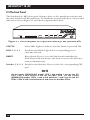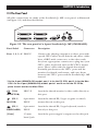
1
APRIL 2001 Mac PC 1 2 3 4 ET 1 2 3 4 RES US STAT SW627A-R2 SW628A-R2 Customer Support Information: FREE tech support 24 hours a day, 7 days a week: Call 724-746-5500 or fax 724-746-0746. Mailing address: Black Box Corporation, 1000 Park Dr., Lawrence, PA 15055-1018 World-Wide Web: www.blackbox.com • E-mail: [email protected] © Copyright 2001. Black Box Corporation. All rights reserved. THE SERVSWITCH™ FAMILY Welcome to the ServSwitchTM Family! Thank you for purchasing a BLACK BOX® ServSwitch™ Brand KVM switch! We appreciate your business, and we think you’ll appreciate the many ways that your new ServSwitch keyboard/video/mouse switch will save you money, time, and effort. That’s because our ServSwitch family is all about breaking away from the traditional, expensive model of computer management. You know, the one-sizefits-all-even-if-it-doesn’t model that says, “One computer gets one user station, no more, no less.” Why not a single user station (monitor, keyboard, and mouse) for multiple computers—even computers of different platforms? Why not a pair of user stations, each of which can control multiple computers? Why not multiple user stations for the same computer? With our ServSwitch products, there’s no reason why not. We carry a broad line of robust solutions for all these applications. Do you have just two PCs, and need an economical alternative to keeping two monitors, keyboards, and mice on your desk? Or do you need to share dozens of computers, including a mix of IBM® PC, RS/6000®, Apple® Macintosh®, Sun Microsystems®, and SGI® compatibles among multiple users with different access levels? Does your switch have to sit solidly on a worktable and use regular everyday cables? Or does it have to be mounted in an equipment rack and use convenient many-to-one cables? No matter how large or small your setup is, no matter how simple or how complex, we’re confident we have a ServSwitch system that’s just right for you. The ServSwitch™ family from Black Box—the one-stop answer for all your KVMswitching needs! * This manual will tell you all about your new ServSwitch™ Jr. MP unit, including how to install, operate, and troubleshoot it. For an introduction to the ServSwitch Jr. MP unit itself, see Chapter 2. The ServSwitch Jr. MP product codes covered in this manual are: SW627A-R2 SW628A-R2 1 SERVSWITCH™ JR. MP TRADEMARKS USED IN THIS MANUAL BLACK BOX and the logo are registered trademarks, and ServSwitch, ServSwitch Jr., and ServSwitch Jr. MP are trademarks, of Black Box Corporation. Apple, Mac, and Macintosh are registered trademarks, and G3 and G4 are trademarks, of Apple Computer, Inc. IBM, PC/AT, PS/2, RS/6000, and ThinkPad are registered trademarks, and PC/XT is a trademark, of International Business Machines Corporation. Microsoft, Windows, and IntelliMouse are registered trademarks or trademarks of Microsoft Corporation in the United States and/or other countries. Sun Microsystems is a registered trademarks of Sun Microsystems, Inc. in the United States and other countries. Any other trademarks mentioned in this manual are acknowledged to be the property of the trademark owners. 2 FCC/IC STATEMENTS FEDERAL COMMUNICATIONS COMMISSION AND INDUSTRY CANADA RADIO-FREQUENCY INTERFERENCE STATEMENTS This equipment generates, uses, and can radiate radio-frequency energy, and if not installed and used properly, that is, in strict accordance with the manufacturer’s instructions, may cause interference to radio communication. It has been tested and found to comply with the limits for a Class A computing device in accordance with the specifications in Subpart J of Part 15 of FCC rules, which are designed to provide reasonable protection against such interference when the equipment is operated in a commercial environment. Operation of this equipment in a residential area is likely to cause interference, in which case the user at his own expense will be required to take whatever measures may be necessary to correct the interference. Changes or modifications not expressly approved by the party responsible for compliance could void the user’s authority to operate the equipment. This digital apparatus does not exceed the Class A limits for radio noise emission from digital apparatus set out in the Radio Interference Regulation of Industry Canada. Le présent appareil numérique n’émet pas de bruits radioélectriques dépassant les limites applicables aux appareils numériques de la classe A prescrites dans le Règlement sur le brouillage radioélectrique publié par Industrie Canada. 3 SERVSWITCH™ JR. MP NORMAS OFICIALES MEXICANAS (NOM) ELECTRICAL SAFETY STATEMENT INSTRUCCIONES DE SEGURIDAD 1. Todas las instrucciones de seguridad y operación deberán ser leídas antes de que el aparato eléctrico sea operado. 2. Las instrucciones de seguridad y operación deberán ser guardadas para referencia futura. 3. Todas las advertencias en el aparato eléctrico y en sus instrucciones de operación deben ser respetadas. 4. Todas las instrucciones de operación y uso deben ser seguidas. 5. El aparato eléctrico no deberá ser usado cerca del agua—por ejemplo, cerca de la tina de baño, lavabo, sótano mojado o cerca de una alberca, etc.. 6. El aparato eléctrico debe ser usado únicamente con carritos o pedestales que sean recomendados por el fabricante. 7. El aparato eléctrico debe ser montado a la pared o al techo sólo como sea recomendado por el fabricante. 8. Servicio—El usuario no debe intentar dar servicio al equipo eléctrico más allá a lo descrito en las instrucciones de operación. Todo otro servicio deberá ser referido a personal de servicio calificado. 9. El aparato eléctrico debe ser situado de tal manera que su posición no interfiera su uso. La colocación del aparato eléctrico sobre una cama, sofá, alfombra o superficie similar puede bloquea la ventilación, no se debe colocar en libreros o gabinetes que impidan el flujo de aire por los orificios de ventilación. 10. El equipo eléctrico deber ser situado fuera del alcance de fuentes de calor como radiadores, registros de calor, estufas u otros aparatos (incluyendo amplificadores) que producen calor. 11. El aparato eléctrico deberá ser connectado a una fuente de poder sólo del tipo descrito en el instructivo de operación, o como se indique en el aparato. 4 NOM STATEMENT 12. Precaución debe ser tomada de tal manera que la tierra fisica y la polarización del equipo no sea eliminada. 13. Los cables de la fuente de poder deben ser guiados de tal manera que no sean pisados ni pellizcados por objetos colocados sobre o contra ellos, poniendo particular atención a los contactos y receptáculos donde salen del aparato. 14. El equipo eléctrico debe ser limpiado únicamente de acuerdo a las recomendaciones del fabricante. 15. En caso de existir, una antena externa deberá ser localizada lejos de las lineas de energia. 16. El cable de corriente deberá ser desconectado del cuando el equipo no sea usado por un largo periodo de tiempo. 17. Cuidado debe ser tomado de tal manera que objectos liquidos no sean derramados sobre la cubierta u orificios de ventilación. 18. Servicio por personal calificado deberá ser provisto cuando: A: El cable de poder o el contacto ha sido dañado; u B: Objectos han caído o líquido ha sido derramado dentro del aparato; o C: El aparato ha sido expuesto a la lluvia; o D: El aparato parece no operar normalmente o muestra un cambio en su desempeño; o E: El aparato ha sido tirado o su cubierta ha sido dañada. 5 SERVSWITCH™ JR. MP Contents Chapter Page 1. Specifications ............................................................................................. 8 2. Introduction ............................................................................................. 2.1 The Complete Package ..................................................................... 2.2 Operating Features ........................................................................... 2.3 The Front Panel ................................................................................ 2.4 The Rear Panel .................................................................................. 2.5 Cable Requirements ......................................................................... 2.6 Equipment Requirements ................................................................ 10 10 10 12 13 14 14 3. Installation ................................................................................................ 3.1 Rackmounting (Optional) ............................................................... 3.2 Connecting the Monitor, Keyboard, and Mouse ............................ 3.3 Connecting the CPUs ....................................................................... 3.4 Powering Up the System ................................................................... 3.5 Switching from the Keyboard ........................................................... 15 15 15 16 17 17 4. Operation ................................................................................................. 4.1 Guidelines for Using the ServSwitch Jr. MP with Your Equipment ........................................................................... 4.1.1 CPUs ........................................................................................ 4.1.2 Mouse and Keyboard .............................................................. 4.1.3 Monitor .................................................................................... 4.2 Keyboard-Command Summary ........................................................ 4.3 The Commands in Detail ................................................................. 4.3.1 Selecting a Port from the Shared Keyboard ......................... 4.3.2 Switching to the Next or Previous Port ............................... 4.3.3 Scan Mode ............................................................................. 4.3.4 Reset ...................................................................................... 4.3.5 Send Null Byte (PC CPUs with PS/2 Mouse Ports Only) ... 4.3.6 Identify ROM ........................................................................ 4.3.7 Keep Settings ......................................................................... 4.3.8 Set Maximum Ports (SW628A-R2 Only) .............................. 4.3.9 Set Scan-Delay Time ............................................................. 4.3.10 Set Keyboard Mode (PC CPUs Only) .................................. 4.3.11 Set Keyboard Typematic ....................................................... 4.3.12 Set Apple Emulation ............................................................ 4.3.13 Set Mouse Translation (PC CPUs with Serial Mouse Ports Only) ................................................ 18 6 18 18 18 20 23 25 25 25 25 25 26 26 26 27 27 27 29 31 33 TABLE OF CONTENTS Chapter 5. Page Troubleshooting ...................................................................................... 5.1 Restoring Factory-Default Settings ................................................... 5.2 Common Problems ........................................................................... 5.2.1 CPU Doesn’t Boot ................................................................. 5.2.2 Can’t Switch Ports from Keyboard ....................................... 5.2.3 Typed Characters Wrong or Missing (PC CPUs Only) ...... 5.2.4 Can’t Switch/Scan to Certain Ports (SW628A-R2 Only) .......................................................... 5.2.5 ServSwitch Jr. MP Scans or Switches to Empty Ports (SW628A-R2 Only) .......................................................... 5.2.6 Mouse Driver Doesn’t Load ................................................. 5.2.7 Can’t Access Mouse Functions ............................................. 5.2.8 PS/2 Mouse Gets Out of Sync (PC CPUs with PS/2 Mouse Ports Only) ................................................... 5.2.9 Mouse Doesn’t Move Pointer/Cursor ................................. 5.2.10 Display is Fuzzy ...................................................................... 5.2.11 Video Not Synchronized or Wrong Color ........................... 5.2.12 Can’t Access High-Resolution Mode (PC CPUs Only) ....... 5.2.13 CPUs Lock Up When Windows 3.x Loaded ........................ 5.2.14 ServSwitch Jr. MP Doesn’t Work with Docking Station ...... 5.2.15 ServSwitch Jr. MP Doesn’t Work with Dongle-Protected Software .............................................. 5.2.16 ServSwitch Jr. MP Doesn’t Work with IBM ThinkPad ........ 5.3 Calling Black Box .............................................................................. 5.4 Shipping and Packaging ................................................................... 34 34 35 35 36 36 36 36 37 37 37 38 38 38 39 39 39 39 39 40 40 Appendix A: NVRAM Factory Defaults ......................................................... 41 Appendix B: Cable Product Codes ................................................................ 42 Appendix C: Rackmounting the ServSwitch Jr. MP ...................................... 44 7 SERVSWITCH™ JR. MP 1. Specifications Compliance — FCC Part 15 Subpart J Class A, IC Class/classe A Standards — With original Serv cabling: VGA (color or monochrome/ page white) and Apple Macintosh video; With original Serv cabling (minimal) or coaxial cabling (recommended): SVGA video; With coaxial cabling: XGA (color or monochrome) and Apple Macintosh video Interfaces — VGA/SVGA/XGA (to monitor); PS/2 keyboard and mouse; PC port(s): Proprietary composite of IBM PC/AT or PS/2 keyboard, RS-232 or PS/2 mouse, and VGA/SVGA/ XGA video; MAC port(s): Proprietary composite of Apple Macintosh keyboard, mouse, and video Resolution — With original Serv cabling: Up to 1024 x 768 noninterlaced; With coaxial cabling: Up to 1600 x 1280 noninterlaced Refresh Rate — Up to 100 Hz Maximum Distance — User Controls — 8 Depending on the CPU, monitor, and video resolution (see Section 4.1.3), either: 20 ft. (6.1 m) of original Serv cable from the ServSwitch Jr. MP to any CPU; or 20 ft. (6.1 m) of coaxial cable—possibly as much as 100 ft. (30.5 m) depending on CPUs—from any ServSwitch Jr. MP to any device attached to it Keyboard commands; Front-mounted membrane switches: Both models: (1) for resetting the Switch; SW627A-R2: (2) for port selection; SW628A-R2: (4) for port selection CHAPTER 1: Specifications Indicators — Both models: (1) for Switch’s power status; SW627A-R2: (2) for port status; SW628A-R2: (4) for port status Connectors — All rear-mounted; Both models: (1) HD15 female for VGA monitor; (2) 6-pin mini-DIN female: (1) for PS/2 keyboard, (1) for PS/2 mouse; SW627A-R2: (2) numbered DB25 female for CPUs; SW628A-R2: (4) numbered DB25 female for CPUs, (1) 3.5-mm barrel jack for power Maximum Altitude — 10,000 ft. (3048 m) Temperature Tolerance — 32 to 131˚F (0 to 55˚C) Humidity Tolerance — 5 to 80% noncondensing Enclosure — Steel Power — 5 VDC at up to 1 A, either from the keyboard-power leads of the attached computers or from the included PS255 external power supply: Input: 115 to 230 VAC at 50 or 60 Hz from utilitypower (mains) outlet through detachable input cord and IEC 320 male inlet on transformer Size — 1.75"H (1U) x 8.8"W x 3.5"D (4.4 x 22.4 x 8.9 cm) Weight — Net: 3 lb. (1.4 kg); Shipping: 4 lb. (1.8 kg) 9 SERVSWITCH™ JR. MP 2. Introduction Thank you for choosing a ServSwitch Jr.™ MP. Designed with your needs in mind, your new Switch will simplify your job by helping you organize your multiplecomputer application. Because the ServSwitch Jr. MP lets you use a single keyboard, monitor, and mouse to access one or two IBM® PC compatible computers and one or two Apple® Macintosh® compatible computers, you can significantly reduce your equipment overhead and end keyboard and monitor clutter. This chapter describes everything that comes with the Switch, the external and operating features of the Switch, and the cabling you’ll need for the Switch. 2.1 The Complete Package Your ServSwitch Jr. MP package includes the ServSwitch Jr. MP, its power supply, and this manual. If anything arrived damaged, contact Black Box. 2.2 Operating Features • With the 2-port model (SW627A-R2), you can access one IBM PC compatible CPU and one Apple Mac® compatible CPU with one keyboard, monitor, and mouse. With the 4-port model, you can access two of each. • Microprocessor-controlled keyboard and mouse switching. • Supports all modes of PS/2® compatible keyboards. • Remaps the keys of the IBM keyboard to support all Apple keyboard functions. • Mouse can be any 2-button PS/2 type by Microsoft® or Logitech™, including a PS/2 “wheel mouse” such as the Microsoft IntelliMouse®. • Simultaneously supports IBM type CPUs with either PS/2 or RS-232 mouse ports. • Support SVGA and color or monochrome XGA or VGA video at resolutions up to 1600 x 1280 noninterlaced, at refresh rates up to 100 Hz (although all video types except VGA require coaxial or special cables). • Support Mac video at 640 x 480 resolution; many other resolutions and several sync options are available if you attach a Mac Adapter for ServSwitch (our product code KV99MA). 10 CHAPTER 2: Introduction • If your application is not very demanding, the Switch can operate using only a portion of the attached computers’ keyboard power. For higher-level applications, an external power supply is included. • You can select the desired CPU from your keyboard or from the Switch’s front panel. • Front-panel LEDs show which CPU is selected. • The units remember and restore Num Lock, Caps Lock, Scroll Lock, and keyboard mode for each CPU. • Scan function can sequence between CPUs every 1 to 15 seconds. • Screen-save function can turn off video after 1 to 999 seconds of inactivity. • You can program the keyboard’s typematic rate and delay. • Custom settings for each CPU can be saved in nonvolatile memory. • Rackmount kits are also available. 11 SERVSWITCH™ JR. MP 2.3 The Front Panel The ServSwitch Jr. MP’s front panel features three or five membrane switches and the same number of LED indicators. To familiarize yourself with these controls and indicators, refer to Figure 2-1 and the descriptions that follow. PC STATUS 1 2 3 4 RESET 1 Mac 2 3 4 Figure 2-1. The front panel of a 4-port ServSwitch Jr. MP (SW628A-R2). STATUS Status LED: Lights to indicate that the Switch is powered ON. LEDs 1, 2, 3, 4 Port-Selection LEDs: Light if the corresponding port is currently selected. RESET Reset Switch: Press to reset the Switch and reinitialize the shared keyboard and mouse; also used to restore the Switch to its factory-default state. Switches 1, 2, 3, 4 Port-Selection Switches: Press to select the corresponding CPU port. NOTE On the 2-port (SW627A-R2) model, LED 1 and switch 1 are for the PC CPU, LED 2 and switch 2 are for the Mac CPU. On the 4-port (SW628A-R2) model, LEDs 1 and 2 and switches 1 and 2 are for the PC CPUs, LEDs 3 and 4 and switches 3 and 4 are for the Mac CPUs. 12 CHAPTER 2: Introduction 2.4 The Rear Panel All cable connections are made at the ServSwitch Jr. MP’s rear panel, as illustrated (in Figure 2-2) and described below. 4 3 2 1 Figure 2-2. The rear panel of a 4-port ServSwitch Jr. MP (SW628A-R2). Panel Label Connector Ports 1, 2, 3, 4* DB25 F Description Connect the sharing computers to these ports with special CPU Cables. At the Switch end, these cables have a DB25 male connector; at the other ends, they have appropriate connectors to plug into your CPUs’ video, keyboard, and (on PC CPUs) mouse ports. These cables take the signals that would normally pass between the CPUs’ ports and the monitor, keyboard, and mouse, and carry them between the CPUs’ ports and the ServSwitch Jr. MP instead. * On the 2-port (SW627A-R2) model, port 1 is for the PC CPU, port 2 is for the Mac CPU. On the 4-port (SW628A-R2) model, ports 1 and 2 are for the PC CPUs, ports 3 and 4 are for the Mac CPUs. (VGA MONITOR) HD15 F Attach the shared monitor’s video cable directly to this port. (PS/2 MOUSE) 6-pin miniDIN F Attach the shared PS/2 type (regular or wheel) mouse directly to this port. (PS/2 KEYBOARD) 6-pin miniDIN F Attach the shared PS/2 type keyboard, attach it directly to this port. [None] 3.5-mm barrel jack Attach the power supply’s output cord to this jack. 13 SERVSWITCH™ JR. MP 2.5 Cable Requirements Many switches of this type have what seems like ten million connectors on their rear panels: one for each CPU’s video cable, one for each keyboard cable, and a third for each mouse cable. The potential for tangling or mismatching cables is high. By contrast, you can connect the ServSwitch Jr. MP to your CPUs with one CPU Cable for each CPU. This single cable reaches the CPU’s video-output, keyboard, and (on PC CPUs) mouse ports. The exact variety or varieties of this cable that you’ll need will depend on the equipment you are connecting for your application. Refer to Appendix B for the available types of this cable and the corresponding product codes. Also refer to Chapter 1 or the first Caution notice in Section 3.3 for information about maximum cabling distances. Finally, you can plug the shared monitor, keyboard, and mouse directly into the ServSwitch Jr. MP. 2.6 Equipment Requirements You will have to be careful to choose a common monitor, keyboard, and mouse that adequately support all of your CPUs. For full details, see Section 4.1. 14 CHAPTER 3: Installation 3. Installation 3.1 Rackmounting (Optional) If you want to mount the ServSwitch Jr. MP in a 19", 23", or 24" rack, you will need a ServSwitch Rackmounting Kit (our product code RMK19M, RMK23M, or RMK24M respectively). The Switch is pre-drilled to accept the Kit’s rackmounting screws. See Appendix C for more information. 3.2 Connecting the Monitor, Keyboard, and Mouse CAUTION! Make sure that the monitor, keyboard, and mouse you plan to use can meet the demands of your application—see Section 4.1. Also, note that the ServSwitch Jr. MP does not support most dongles. 1. After you verify that the ServSwitch Jr. MP is powered OFF, plug the HD15 male connector of the video cable from your monitor into the HD15 female port on the ServSwitch Jr. MP’s rear panel that’s labeled with the monitor icon ( ). 2. Plug the 6-pin mini-DIN male connector of your PS/2 type keyboard’s cable into the 6-pin mini-DIN female port on the ServSwitch Jr. MP’s rear panel that’s labeled with the keyboard icon ( ). 3. Plug the 6-pin mini-DIN male connector of your regular PS/2 or PS/2 wheel type mouse’s cable into the 6-pin mini-DIN female port on the ServSwitch Jr. MP’s rear panel that’s labeled with the mouse icon ( ). 15 SERVSWITCH™ JR. MP 3.3 Connecting the CPUs CPU Cables run from the ServSwitch Jr. MP to the keyboard port, video-output port, and (on PC CPUs) mouse port of each CPU you want to directly attach to it. Different types of this cable fit the connectors on different computers (see Appendix B). This cable also comes in the different lengths supported by different applications (see Section 4.1.3). CAUTION! Avoid routing cable near fluorescent lights, air-conditioning compressors, or machines that may create electrical noise. Total length of original Serv cable from a ServSwitch Jr. to any given CPU should not exceed 20 feet (6.1 m). For typical equipment and video resolutions, length of coaxial cable should not exceed 20 ft. (6.1 m) from a ServSwitch Jr. MP to any attached device (keyboard, monitor, mouse, or CPU). However, we do provide coaxial cable in lengths up to 100 ft. (30.5 m), because some CPUs can drive and receive keyboard and mouse signals at greater distances than others. To go even farther, you might want to use Station Extenders or CAT5 KVM Extenders. See Appendix B. 1A. SW627A-R2: After you verify that the ServSwitch Jr. MP is powered OFF, plug the DB25 male composite connector of the PC CPU’s CPU Cable into the port labeled “1” on the Switch’s rear panel. Plug the CPU Cable you’re running to the Mac CPU into the port labeled “2”. 1B. SW628A-R2: After you verify that the ServSwitch Jr. MP is powered OFF, plug the DB25 male composite connector of the first PC CPU’s CPU Cable into the port labeled “1” on the Switch’s rear panel. Plug the CPU Cable you’re running to the first Mac CPU into the port labeled “3”. If you’re using a second PC, plug the third CPU Cable into the port labeled “2”; if you’re using a second Mac, plug the fourth CPU Cable into the port labeled “4”. 2. Plug each CPU Cable’s video-, keyboard-, and mouse-port connectors into the corresponding ports on the CPU. The CPU should be OFF when you do this; the Switch will automatically adjust to the CPU’s keyboard mode when you power up the CPU. Avoid plugging CPUs into the Switch if they are already ON; if you accidentally do so, see Section 4.3.10 to make sure the Switch is set for the proper keyboard mode. NOTE Newer G3™, G4™, and similar Mac computers have HD15 VGA ports rather than traditional DB15 Mac video ports. If you have such a CPU with ADB (legacy) keyboard and mouse ports, you’ll need to use a Mac Gx type cable (EHN550 or EHN560) to connect it to a Mac port on a ServSwitch Jr. MP. If your G3 or G4 type CPU has USB keyboard and mouse ports instead, call Black Box for technical support. 16 CHAPTER 3: Installation CAUTION! Do not attach docking stations for older models of the ThinkPad® or other portable computers to the ServSwitch Jr. MP. The Switch currently supports only “stream mode” (continuous) mouse data, but older ThinkPad models have to see “prompt mode” (burst-on-request) mouse data. Some newer docking stations and some newer ThinkPad models might work with the Switch, but determining whether a particular unit will do so will probably require trial and error. 3.4 Powering Up the System To connect the power supply, first insert the plug of the power supply’s output cord into the 3.5-mm barrel jack on the rear panel of the ServSwitch Jr. MP. Then plug the IEC 320 female outlet on one end of the power supply’s detachable input cord into the IEC 320 male inlet on the supply’s transformer. Finally, insert the country-specific plug at the other end of the input cord into a working utilitypower (mains) outlet. The Switch will begin operating immediately; it has no ON/OFF switch. Now power up the connected CPUs one by one, giving each one time to boot completely before turning ON the next one. (If you’re not using the power supply, the ServSwitch Jr. MP itself will begin operating as soon as you turn ON the first CPU; it will get its power from the CPUs and has no ON/OFF switch.) To boot a Mac using a 101- or 102-key PC keyboard, first boot an attached PC, then select the CPU port of the Mac, then press the right Control ([CTRL]) key (see Section 4.3.12 for a full list of remapped keyboard keys). The Switch emulates all keyboard and mouse functions for automatic boot-up, although you might have to issue the Mode command Mn (see Section 4.3.10) to get proper keyboard communication with your PC CPU(s). 3.5 Switching from the Keyboard Your ServSwitch Jr. MP is now ready for operation using its default settings. To take full advantage of the Switch’s features, refer to Chapter 4, which gives detailed information about each of the Switch commands, describing each command’s function and keystroke sequence. For your convenience, this information is summarized in Section 4.2. To begin switching immediately, however, just press and release your keyboard’s left Control ([CTRL]) key, then—within the next two seconds—type in your desired port number with the regular number keys (not the numeric keypad). 17 SERVSWITCH™ JR. MP 4. Operation The first part of this chapter, Section 4.1, gives you some guidelines that you should follow to make sure your ServSwitch Jr. MP works properly with your equipment. Section 4.2 summarizes the ServSwitch Jr. MP’s keyboard commands, and Section 4.3 describes these commands in detail. NOTES To start any ServSwitch Jr. MP keyboard command, you must press and release the left Control Key ([CTRL]). Pressing and releasing [CTRL] cues the Switch to expect command characters from the keyboard. You then have two seconds in which to start entering a valid command. If no command is begun within two seconds or if an invalid command is entered, the Switch aborts the command. When entering commands that contain numbers or math symbols, use only the numeral keys located at the top of your alphanumeric keyboard. Numbers and symbols entered from the numeric keypad to the right will not be recognized as valid. 4.1 Guidelines for Using the ServSwitch Jr. MP with Your Equipment 4.1.1 CPUS Use only IBM PC/AT or PS/2 or 100% compatible machines on the PC side. The ServSwitch Jr. MP does not support IBM PC/XT™ or compatible machines. It also does not support machines that output CGA or EGA video. 4.1.2 MOUSE AND KEYBOARD When you power up your ServSwitch Jr. MP system, make sure that your CPUs, mice, and keyboards are properly cabled to the ServSwitch Jr. MP. When you boot up the CPUs, the ServSwitch Jr. MP should start operating automatically. (You should be able to freely disconnect and reconnect a mouse or keyboard from a ServSwitch Jr. MP while the Switch is ON, but if you experience problems when you do this, issue the Reset command [CTRL] R—see Section 4.3.4.) The mouse must be a 2-button PS/2 type mouse by Microsoft or Logitech™, or a 3-button or “wheel” PS/2 mouse such as the Microsoft IntelliMouse. The ServSwitch Jr. MP is designed to support IBM PS/2 compatible 101- through 105-key keyboards and IBM keyboard-scan modes 1, 2, and 3, and it’s designed to work with keyboards that use 6-pin mini-DIN keyboard connectors. The Switch 18 CHAPTER 4: Operation might not work properly with keyboards that have proprietary keys or connectors or use proprietary keyboard-scan modes. Standard PC keyboards have between 101 and 105 keys. In order to reproduce all of the functions of the Apple keyboard, which has 105 keys (not all the same as those on the 105-key PC keyboard), we have “mapped” several of the special Apple keys to other keys on the PC keyboard. You can select any of three different mapping options; see Section 4.3.12 for a full rundown. Other concerns: • Because the ServSwitch Jr. MP currently only supports “stream mode” (continuous) mouse data but older IBM ThinkPad models have to handle mouse data in “prompt mode” (burst-on-request), don’t try to attach any older ThinkPad computers to the Switch, either directly or through docking stations. Some newer models should work with the Switch, but there’s no good way to tell other than by trial and error. (You can’t damage your equipment by trying—if you have the wrong kind of ThinkPad, it just won’t work.) • Make sure that the IBM PC CPU(s) use only the generic Microsoft mouse driver MOUSE.COM, version 4.0 at least and preferably version 9.01 or higher. If you’re running Windows® 3.x, this driver must be loaded in Windows as well as in the base operating system. On PCs, do not run any programs or TSRs, or enter any DOS commands, that change the settings of the mouse port after the driver has been loaded. • When you first switch between CPUs, especially from the PC CPU to a Mac CPU or vice versa, you might notice wide variations in mouse sensitivity (how far or fast the mouse moves) from CPU to CPU. This is normal. Both the PC and Apple platforms have ways to adjust the sensitivity of the mouse. (This is usually handled through some kind of software “control panel,” but the specifics vary depending on the operating system and—in IBM applications— on the mouse driver.) To optimize mouse movement, adjust the sensitivity on each CPU according to your individual preference. • Although the ServSwitch Jr. MP resists minor transient surges that can be caused by rapidly cycling power, certain keyboards are sensitive to such transients. Because your shared keyboard’s power comes through the Switch, wait at least three seconds after powering down the Switch before powering it up again, or the keyboard might not reset correctly. 19 SERVSWITCH™ JR. MP 4.1.3 MONITOR NOTE No keyboard/video switch can provide perfect video. You will see at least a little fuzziness on your monitor no matter how close to ideal your ServSwitch Jr. MP system is. While PC-type CPUs and VGA monitors normally use two separate leads to send/receive sync signals (one lead for horizontal sync and one for vertical sync), Mac CPUs/monitors normally send/receive a composite sync signal on a single lead. This means that either your monitor must be capable of accepting both H/V and composite-sync input, or you will have to attach a Mac Adapter for ServSwitch (our product code KV99MA) to the Mac in order to resynchronize its video-port output. For maximum compatibility, we recommend a 17" or larger, high-quality multisync monitor capable of (a) displaying a maximum resolution of not less than 1280 x 1024 at a maximum refresh rate of not less than 75 Hz, and (b) accepting both relevant types of sync input (H/V and composite). Such monitors are available from many manufacturers. The ServSwitch Jr. MP is designed to support standard VGA video, including VGA monochrome (“page white”). It does not support PCs that use CGA, EGA, or proprietary versions of VGA that depart from the original specifications. Consult your PC’s manual, and if that doesn’t tell you whether or not the PC uses standard VGA, consult with the PC’s or the video card’s manufacturer. The ServSwitch Jr. MP is also designed to support SVGA, although we recommend coaxial cabling for this, especially for higher resolutions. With coaxial cables, the Switch will also support XGA. 20 CHAPTER 4: Operation The ServSwitch Jr. will support SVGA (Super VGA) video, but with original Serv cables the video quality for SVGA and Mac video will decrease markedly at higher resolutions and distances. Table 4-1 illustrates this. The distances in the table are total cable lengths measured from the CPU to the monitor. Table 4-1. Video Quality vs. Distance for Original Serv Cables Distance 5' (1.5 m) 10' (3 m) 15' (4.6 m) 20' (6.1 m) 25' (7.6 m) Resolution 640 x 480 3 3 3 3 3 800 x 600 noninterlaced 3 3 3 2 2 1024 x 768 interlaced 3 3 2 2 2 1024 x 768 noninterlaced 3 2 2 2 2 1280 x 1024 interlaced 2 1 1 1 1 1280 x 1024 noninterlaced 2 1 1 1 1 1600 x 1280 noninterlaced 2 1 1 1 1 Quality 3 = Near perfect; screen defects are not conspicuous Quality 2 = Good to very good; images are clear; there are small reflections around text lettering depending on the color; screen defects are sometimes conspicuous Quality 1 = Fair to poor as distance increases; images run from slightly fuzzy to badly smeared; text runs from fuzzy but readable to completely washed out 21 SERVSWITCH™ JR. MP By contrast, coaxial cables (required for XGA applications, and recommended for most other applications) do much better at maintaining video quality, as shown in Table 4-2. (For the meaning of quality numbers 3, 2, and 1, see the bottom of the previous page.) As before, the distances in the table are total cable lengths measured from the CPU to the monitor. Table 4-2. Video Quality vs. Distance for Coaxial Cables Distance Resolution 10 ft. 20 ft. 30 ft. 50 ft. 75 ft. 100 ft. 150 ft. 200 ft. (3 m) (6.1 m) (9.1 m) (15.2 m) (22.9 m) (30.5 m) (45.7 m) (61 m) 640 x 480 3 3 3 3 3 3 2 2 800 x 600 noninterl. 3 3 3 3 3 3 2 2 1024 x 768 interlaced 3 3 3 3 3 3 2 2 1024 x 768 noninterl. 3 3 3 3 2 2 2 1 1280 x 1024 interlaced 3 2 2 2 2 1 1 1 1280 x 1024 noninterl. 3 2 2 1 1 1 1 1 1600 x 1280 noninterl. 3 2 2 1 1 1 1 1 CAUTION! Some CPUs can’t drive or receive keyboard and mouse signals across longer runs of coaxial cable. Consult with the manufacturers of your CPUs before installing this cable in lengths greater than 20 ft. (6.1 m). For CPU-to-monitor distances over 200 feet (61 m), Station Extenders or CAT5 KVM Extenders might be required. Call Black Box for technical support to discuss this option. 22 CHAPTER 4: Operation 4.2 Keyboard-Command Summary Table 4-3 on this page and the next page summarizes the commands that can be sent to the ServSwitch Jr. MP. To enter any command at the shared keyboard, first press and release the left Control Key ([CTRL]). This cues the Switch to look for commands from the keyboard. Then enter the command followed by any arguments you wish to specify (the port number, for example). Letter commands are not case-sensitive; they are all shown in uppercase for clarity only. When you enter numeric commands or arguments, use only the numbered keys at the top of your alphanumeric keyboard. Numbers entered from the numeric keypad to the right will not be recognized as valid commands. All of these commands have a two-second timeout between characters. This means that if you begin entering a command, but you stop for more than two seconds at any time before you type the final character, the command is aborted and the ServSwitch Jr. MP returns to normal operation. This keeps the Switch from getting stuck waiting for you to finish the command. The [CTRL] character is always passed through to the CPU. The command characters and operands, however, are absorbed by the ServSwitch Jr. MP and are not sent to the CPU. Many of these commands have factory-default values (see Appendix A) that can be reloaded if your Switch becomes badly misconfigured; see Section 5.1. Table 4-3. The ServSwitch Jr. MP’s Keyboard Commands Command Keystroke Sequence Description Select Port [CTRL] xxx (xxx = a 1- to 3-digit port number) Connects your shared monitor, keyboard, and mouse (user station) to the specified port. Switch to the Next Port [CTRL] + Switches to the next port in sequence. Switch to the Previous Port [CTRL] – Switches to the previous port in sequence. Scan ON [CTRL] S Turns Scan mode ON, causing the ServSwitch Jr. MP to start scanning sequentially from the current port through the remaining ports and then begin again at Port 1. 23 SERVSWITCH™ JR. MP Command Keystroke Sequence Description Scan OFF [CTRL] X Turns Scan mode OFF (the port being scanned at the time the command is entered is given access to the shared monitor, keyboard, and mouse). Note: Scan can also be stopped by entering a Select Port command. Reset [CTRL] R Resets and enables the keyboard and mouse. Issue this command to correct your keyboard or mouse if one of them malfunctions or gets stuck. Send Null Byte [CTRL] N PC CPUs with PS/2 mouse ports only: Causes the ServSwitch Jr. MP to send a null byte to the CPU’s PS/2 mouse port. Issue this command to correct the current CPU if it gets “out of sync” with the PS/2 mouse (see Section 4.3.5). Identify ROM [CTRL] I Causes the ServSwitch to report the version of ROM it is using. Issue this command if you are asked to do so by a technical-support person. Keep Settings [CTRL] K Enter this command after you enter any of the following six commands (it saves new settings to nonvolatile memory): Set Maximum Number of Ports [CTRL] Px [ENTER] (x = 2 or 3) SW628A-R2 only: Tells the ServSwitch Jr. MP the total number of ports to which devices are (or will be) connected. Issue this command when you’re only using 2 or 3 of the ports on a 4-port unit. Set ScanDelay Time [CTRL] Txx [ENTER] (xx = delay in seconds from 1 to 15) Sets the time, in seconds, that the ServSwitch Jr. MP will pause at each port when scanning. Set Keyboard Mode [CTRL] Mx [ENTER] (x = 1, 2, or 3) PC CPUs only: Tells the ServSwitch Jr. MP the keyboard mode of the currently selected CPU. Set Keyboard Typematic [CTRL] Axxx [ENTER] (xxx = a decimal value from 0 to 127) Sets the keyboard typematic (automatic keyrepeat) function of the currently selected CPU. This command works only with CPUs that have standard keyboards and CMOS that allows users to program the typematic function. Set Apple Emulation [CTRL] Ex [ENTER] (x = 0, 1, or 2) Determines how your PC-keyboard keys are mapped to Apple keyboard keys and functions. Set Mouse Translation [CTRL] Qx [ENTER] (x = 0 or 1) PC CPUs with RS-232 mouse ports only: Q1 turns on PS/2 to RS-232 mouse translation for the currently selected PC. Q0 turns it off. 24 CHAPTER 4: Operation 4.3 The Commands in Detail 4.3.1 SELECTING A PORT FROM THE SHARED KEYBOARD To select a port from your keyboard, press and release your keyboard’s left Control Key ([CTRL]), then press the number key corresponding to the number of your desired port ([1], [2], [3], or [4]). The ServSwitch Jr. MP will immediately switch to that port. You can always, of course, select any port by pressing its numbered button on the Switch’s front panel. 4.3.2 SWITCHING TO THE NEXT OR PREVIOUS PORT From the keyboard you can go forward or backward through the ServSwitch Jr. MP’s ports by selecting either the next or the previous port respectively. To switch to the next port, press and release the left Control Key ([CTRL]), then press the plus key (the key at the top of the keyboard marked with [=] and [+]). To switch to the previous port, press and release [CTRL], then press the minus key (the key at the top of the keyboard marked with [–] and [_]). The command is not casesensitive. Do not use the [+] and [–] keys on the keyboard’s numeric pad; the Switch doesn’t recognize these. 4.3.3 SCAN MODE To enable scanning (switching from CPU to CPU in a continuous rotation) from the keyboard, press and release the left Control Key ([CTRL]), then press [S]. The ServSwitch Jr. MP will begin scanning sequentially from its currently selected port through the higher-numbered ports, then begin again at CPU Port 1. As it scans, it delays 1 to 15 seconds at each port. (This “Scan-Delay Time” is user-selectable; see Section 4.3.9.) To stop scanning, press and release [CTRL], then press [X]. You can also disable scanning by entering a Select Port command. (ServSwitch Jr. MP letter commands are not case-sensitive: You can enter upper- or lower-case letters.) 4.3.4 RESET This command, along with the commands described in the next two sections, comes in handy when certain problems arise. It will reset or refresh your shared equipment. Issue it if (a) your shared keyboard gets stuck or begins behaving oddly, (b) you need to send mouse data to a CPU that hasn’t enabled the mouse (this can happen if you boot up the CPU while the ServSwitch Jr. MP is off or disconnected), or (c) while using a PS/2 type mouse, you unplug it, then plug it back in. To issue the Reset command, press and release the left Control Key, then type [R]. (If you’re using a PS/2 type mouse, don’t issue this command to a PC type CPU that doesn’t have a mouse driver loaded. Many PCs will crash if you send them unexpected mouse data.) 25 SERVSWITCH™ JR. MP 4.3.5 SEND NULL BYTE (PC CPUS WITH PS/2 MOUSE PORTS ONLY) PS/2 type mice send control data to CPUs in three-byte increments. Sometimes, because of electronic transients, unusual power-up effects, or plugging and unplugging of cables from live equipment, the currently selected PC type CPU in a ServSwitch Jr. MP system can lose one or two bytes of this control information and get “out of sync” with the shared mouse. In this situation, the mouse might seem to refuse to move the pointer or cursor, open windows for no reason, or exhibit other strange behavior. To get the CPU back in sync, send this command to tell the Switch to send a “null byte” to the CPU’s PS/2 mouse port (this has no other effect than getting the CPU “caught up”). To issue the Send Null Byte command, press and release the left Control Key, then type [N]. If the mouse still isn’t right after you issue this command, the CPU must have been two bytes out of sync. Issuing the command again should do the trick. The CPU will be thrown out of sync if it has a PS/2 mouse port and it’s in sync when you issue this command. Issue this command two more times to get it back in sync again. This command has no effect on Mac CPUs or on CPUs that are attached to the Switch through an RS-232 mouse port. If you have version 9.01 or higher of the Microsoft mouse driver, the CPU should never get out of sync. Contact Microsoft if you would like to upgrade your Microsoft mouse driver. 4.3.6 IDENTIFY ROM Unfortunately, as with all complex equipment, problems might arise with your ServSwitch Jr. MP that require the assistance of technical-support personnel. One of the things technicians might want to know when they attempt to diagnose and correct your problem is the revision level of your Switch’s ROM. This command causes the ServSwitch Jr. MP to send the three-character “x.x” ROM level to the currently selected CPU as ASCII keyboard data; these characters will be echoed back to the shared monitor if you are at some type of prompt. (You must be at some kind of prompt or screen capable of displaying typed-in keyboard characters, or you will not see the Switch’s response.) To issue the Identify ROM command, press and release the left Control key, then type [I]. 4.3.7 KEEP SETTINGS The Keep Settings command saves the current state of the ServSwitch Jr. MP’s keyboard-selectable settings to nonvolatile memory (NVRAM), where they become the new default (loaded at power-up) settings. To enter the command from your keyboard, press and release the left Control Key, then type [K]. The six keyboardselectable settings are described in the next six sections. 26 CHAPTER 4: Operation 4.3.8 SET MAXIMUM PORTS (SW628A-R2 ONLY) Use this command to tell a 4-port ServSwitch Jr. MP the total number of CPU ports to which computers are or will be connected. This allows the scan function to cycle correctly if you have computers attached to only two or three of the Switch’s CPU ports. To issue the Set Maximum Ports command, press and release the left Control Key, type [P] followed by the total number of ports accessible to that Switch ([2] or [3]), and press [ENTER]. To save a new Maximum Ports setting, you must issue a Keep Settings command. 4.3.9 SET SCAN-DELAY TIME Issue the Set Scan-Delay Time command to set how long, in seconds, the ServSwitch Jr. MP will pause at each of the CPU ports when it’s scanning them. The factory-default setting is 5 seconds. To set a different delay time, press and release the left Control Key, type [T] followed by the new delay time in seconds (1 to 15), and press [ENTER]. (If you issue this command with an argument of zero, the ServSwitch Jr. MP will set the scan-delay time to the default value most recently saved in NVRAM.) Enter the Keep Settings command after you enter this command. 4.3.10 SET KEYBOARD MODE (PC CPUS ONLY) Keyboard “modes” are electrical signaling protocols that determine how a powered PC type CPU and keyboard interact. A CPU and keyboard must use the same mode in order to work with each other. Of the three standard keyboard modes currently in use, mode number 2 is the one used by the vast majority of PC CPUs. It is also the default state of all 101-key and PS/2 keyboards. Mode 1 is used primarily by certain PS/2 CPUs. Mode 3 is used by RS/6000® CPUs, some other UNIX® based computers, and certain specialized servers. The ServSwitch Jr. MP supports all three of these modes: As it receives signals from one of the keyboards, it sends them to the currently selected PC CPU by emulating a keyboard of the appropriate mode for that CPU; as it receives signals for one of the keyboards from the currently selected or scanned CPU, it sends them to that keyboard by emulating a CPU of the appropriate mode. Most CPUs that use keyboard mode 1 or 3 send a “mode command” to the keyboard at power-up, to put the keyboard in the proper mode. A ServSwitch Jr. MP can use these commands to automatically detect each such CPU’s keyboard mode when you turn on the CPU after it has been cabled to the Switch. However, the Switch doesn’t automatically save this value; unless you send it a Keep Settings command, it will forget the modes it has detected when it is powered down, then default to each port’s most recently saved setting when it’s powered up again. 27 SERVSWITCH™ JR. MP The ServSwitch Jr. MP can’t detect the CPU’s keyboard mode if the CPU doesn’t send “mode commands” (most CPUs that use mode 2 fall into this category) or if the CPU is already ON when you connect it to the Switch (it shouldn’t be). In these situations, the Switch tries to use the keyboard-mode setting stored in its nonvolatile memory for that port. The factory-default is mode 2 for all ports. Send the Set Keyboard Mode command to change the keyboard mode for a port if: • the CPU on that port uses mode 1 or 3, • it uses mode 2, but the default setting of the port you want to connect it to has been changed, or • you don’t know which mode the CPU uses or the port is set for, but the keyboard’s behavior makes you suspect that the port’s setting is wrong. To set the keyboard mode of the currently selected port on a ServSwitch Jr. MP, press and release the left Control Key, type [M], and press the numeral key of the mode number ([1], [2], or [3]). After you enter this command, enter the Keep Settings command to save the mode setting in NVRAM, so that the new setting becomes the default value (preserved during power-down and reloaded at powerup). If most or all of the CPUs you’ll be connecting to your ServSwitch Jr. MP system use a keyboard mode other than 2, you might want to change the defaults of their Switch ports at installation time. This is because when power outages occur, the Switch ports will return to their default keyboard mode when the power comes back on. 28 CHAPTER 4: Operation 4.3.11 SET KEYBOARD TYPEMATIC Most IBM PC type keyboards have an internal seven-bit “typematic” setting, which governs the way the keyboard responds when you hold a key down to force it to repeat. The five “low” bits of this setting represent the rate at which the key repeats; the two “high” bits represent the delay after you begin holding down the key before it begins to repeat. Sometimes a keyboard’s typematic setting isn’t suitable for a given operator or for a given application. To change the typematic setting of your station’s shared keyboard, issue the Set Keyboard Typematic command: Press and release the left Control Key, type [A] followed by the desired “typematic value,” and press [ENTER]. The “typematic value” is the decimal equivalent of the binary seven-bit typematic setting: While the typematic setting = delay bits + rate bits, the typematic value = decimal delay value + decimal rate value (see Table 4-4 below and Table 4-5 on the next page). For example, to set your shared keyboard to register a key 16 times per second after the key has been held down for half a second (typematic value = 7 + 32 = 39), type [CTRL] [A] [3] [9] [ENTER]. Enter the Keep Settings command after you enter this command. Because Apple computers do not support the typematic feature, this setting will have no effect when you are working with the attached Mac CPU(s). Table 4-4. Typematic Delay Decimal Value Binary Bit Values Delay Before Key Repeats 0 00[xxxxx] 1 32 01[xxxxx] 1 64 10[xxxxx] 3 96 11[xxxxx] 1 second (1000 ms) ⁄4 second (250 ms) ⁄2 second (500 ms) ⁄4 second (750 ms) 29 SERVSWITCH™ JR. MP Table 4-5. Typematic Rate Decimal Value 0 1 2 3 4 5 6 7 8 9 10 11 12 13 14 15 16 17 18 19 20 21 22 23 24 25 26 27 28 29 30 31 30 Binary Bit Values [xx]00000 [xx]00001 [xx]00010 [xx]00011 [xx]00100 [xx]00101 [xx]00110 [xx]00111 [xx]01000 [xx]01001 [xx]01010 [xx]01011 [xx]01100 [xx]01101 [xx]01110 [xx]01111 [xx]10000 [xx]10001 [xx]10010 [xx]10011 [xx]10100 [xx]10101 [xx]10110 [xx]10111 [xx]11000 [xx]11001 [xx]11010 [xx]11011 [xx]11100 [xx]11101 [xx]11110 [xx]11111 Repeat Rate in Keys per Second 30 26.7 24 21.8 20 18.5 17.1 16 15 13.3 12 10.9 10 9.2 8.6 8 7.5 6.7 6 5.5 5 4.6 4.3 4 3.7 3.3 3 2.7 2.5 2.3 2.1 2 CHAPTER 4: Operation 4.3.12 SET APPLE EMULATION Your shared keyboard must be an IBM PC type. In order for you to be able to reproduce all of the keyboard-driven functions of your Mac CPUs, the ServSwitch Jr. MP has to “map” some of the important keys on the Mac keyboard to keys on the PC keyboard that are either duplicates of other keys or keys that are not used in a Mac environment. (This is called “keyboard emulation.”) The Switch can map the Apple keys in any of the three ways shown below and on the next page; use the Set Apple Emulation command to select the mapping that’s appropriate for your keyboard type and your user history. To issue the Set Apple Emulation command, press and release the left Control Key, type [E], and press the numeral key of your desired mapping number ([0], [1], or [2]). (Use the number keys at the top of the keyboard, not those on the numeric keypad.) Enter the Keep Settings command after you enter this command. [E][0]: Standard Mapping (104/105-Key Keyboard, PC Users) If your keyboard was made within the last few years, chances are it’s one of the 104or 105-key keyboards with special keys (the left and right Start keys and the App [Application] key) designed to trigger Windows 95/Windows 98 functions. Because they have so many keys, these Windows keyboards can be mapped to reproduce all of the keys on an Apple keyboard. And the factory-default keyboard mapping for the ServSwitch Jr. MP assumes that the keyboard you will be using with the Switch is, in fact, one of this type. In its default state (equivalent to the [E][0] setting), the ServSwitch Jr. MP maps the keys of the Windows 95 keyboard as shown below. PC users, especially those who have used the 104/105-key keyboard for some time, will probably be comfortable with this arrangement: On the IBM PC 104/ 105-key keyboard, this key: Emulates this key on the Apple keyboard: Left Ctrl Left Control Left Windows Start ( ) Left Command () Left Alt Left Option (alt) Right Alt or Alt Graph Left Option (alt) Right Windows Start ( Windows App ( Right Ctrl ) ) Left Command () Power ( ) Left Control 31 SERVSWITCH™ JR. MP [E][1]: Swapped Mapping (104/105-Key Keyboard, Mac Users) For those of you who are used to the placement of the command and option keys on the Apple keyboard and would like to preserve that key arrangement on the Windows keyboard, you can enter the [E][1] command to switch to a mapping that swaps the command- and option-key equivalences: On the IBM PC 104/ 105-key keyboard, this key: Emulates this key on the Apple keyboard: Left Ctrl Left Control Left Windows Start ( ) Left Option (alt) Left Alt Left Command () Right Alt or Alt Graph Left Command () Right Windows Start ( Windows App ( ) Right Ctrl ) Left Option (alt) Power ( ) Left Control [E][2]: Older-Keyboard Mapping (101/102-Key Keyboard, All Users) Those of you who are using one of the older 101/102-key PC keyboards can enter the [E][2] command to switch to the standard 101/102-key mapping: 32 On the IBM PC 101/ 102-key keyboard, this key: Emulates this key on the Apple keyboard: Left Ctrl Left Control Left Alt Left Command () Right Alt or Alt Graph Right Option Right Ctrl Power ( ) CHAPTER 4: Operation 4.3.13 SET MOUSE TRANSLATION (PC CPUS WITH SERIAL MOUSE PORTS ONLY) If each IBM PC CPU attached to your ServSwitch Jr. MP has a PS/2 mouse port, you can plug a PS/2 mouse into the Switch and control them both without having to reconfigure the system at all. However, if an attached PC CPU has an RS-232 serial mouse port, you’ll need to set the Switch to do PS/2 to RS-232 mouse translation for the serial-mouse CPU. To enable mouse translation for a serialmouse CPU, select that CPU’s port, then type [CTRL] [Q] [1] [ENTER]. Enter the Keep Settings command after you enter this command. If later you attach a computer with a PS/2 mouse port to that CPU port on the Switch, type [CTRL] [Q] [0] [ENTER] to disable mouse translation, then enter the Keep Settings command. 33 SERVSWITCH™ JR. MP 5. Troubleshooting The first two sections of this chapter discuss some of the problems that can arise in a ServSwitch Jr. MP system and suggest possible causes and solutions. If the trouble you’re having with the Switch is something you haven’t seen before, or if the trouble seems minor, try the procedure detailed in Section 5.1 before doing anything else. If the trouble is chronic, see Section 5.2. Sections 5.3 and 5.4 discuss what’s involved in calling Black Box and shipping your Switch. CAUTION! Do not open the ServSwitch Jr. MP’s cover. You could easily damage the Switch and attached devices, and if the Switch is powered you could hurt yourself as well. 5.1 Restoring Factory-Default Settings If you’re having difficulty with a ServSwitch Jr. MP, something that often helps is resetting the Switch to its factory defaults. Follow these steps carefully: 1. Make sure that at least one powered CPU is attached to the ServSwitch Jr. MP (it doesn’t matter to which port). 2. Press and hold the “1” button on the ServSwitch Jr. MP’s front panel. 3. Press and release the RESET button, then release the “1” button. The POWER LED should flash three times, and the unit should be restored to the factory-default settings listed in Appendix A. Now reconfigure the Switch to your desired settings. If you’re still having difficulty, refer to Section 5.2. If it doesn’t help you to solve your problem, call Black Box for technical support. 34 CHAPTER 5: Troubleshooting 5.2 Common Problems 5.2.1 A CPU CONNECTED TO YOUR SWITCH DOESN’T BOOT, AND YOU GET A KEYBOARD OR MOUSE ERROR A. First make sure that the CPU is in fact connected to the ServSwitch Jr. MP and that the Switch is receiving power. (One of the Switch’s numbered CPU ports must be cabled to the keyboard port of a powered CPU in order for the Switch to work properly.) B. If the Switch is ON, make sure its keyboard and mouse settings are correct. C. If the configuration is OK, check your cables. Tighten any loose connections. If the keyboard and mouse strands of the CPU Cable have been reversed, plug them into the proper ports. D. If you don’t find a cable error, try swapping in different keyboards and/or mice one at a time. If the problem goes away when you substitute a device, the old one might have gone bad. E. If swapping input devices doesn’t solve the problem, begin swapping your cables one at a time. If the problem goes away when you substitute a cable, the old cable is probably defective. F. If swapping cables doesn’t solve the problem, and the Switch is a 4-port (SW628A-R2) model, try plugging the CPU into the other CPU port on the Switch that’s designed for that platform (that is, the other PC port or the other Mac port). If the CPU boots when it’s connected to a different port, the old port is probably defective. G. If you’re using an SW627A-R2 or if swapping ports doesn’t solve the problem, try plugging a known-good keyboard and mouse directly into the CPU that’s having the problem. If the CPU boots, the Switch might be defective; call Black Box. H. If the CPU still doesn’t boot, the CPU’s keyboard or mouse port (or other components) might be defective. (If the CPU’s Power LED doesn’t light, the fuse on the CPU’s motherboard might be blown.) If you still have them, plug that CPU’s original monitor, keyboard, and mouse into it and try again. If the CPU does not boot with its original equipment, something in the CPU is defective; call the CPU’s manufacturer. If the CPU does boot, there is some kind of unusual mismatch between that CPU and the shared monitor, keyboard, or mouse; call Black Box for technical support. 35 SERVSWITCH™ JR. MP 5.2.2 YOU CAN’T SWITCH PORTS FROM THE KEYBOARD A. Can you do anything from the keyboard? If not, the keyboard cable has probably come loose. Reconnect it. B. The ServSwitch Jr. MP might have lost power for less than three seconds. (This can cause the keyboard to lock up.) Disconnect the keyboard and plug it back in. C. The keyboard mode that the currently selected CPU port is set for doesn’t match the mode that the CPU on that port expects. Issue the Set Keyboard Mode command to change the port’s mode (see Section 4.3.10). Sometimes this situation can confuse the CPU or keyboard so badly that it is necessary to reboot the CPU or to reset the keyboard by unplugging it and plugging it back in. D. For PS/2 type equipment, if the keyboard and mouse strands of the CPU cable have been reversed, plug them into the proper ports. E. You might be using the keyboard incorrectly. Make sure to use the left Control key to start port-switching commands. Make sure to use the numeric keys at the top of the keyboard rather than the numeric keypad when you type in port numbers. Make sure to release the Control key before you start typing in a port number. Make sure you don’t wait too long before you enter a port number. Make sure you don’t accidentally hit keys such as Shift or Alt. 5.2.3 CHARACTERS THAT YOU TYPE COME UP WRONG OR MISSING (PC CPUS ONLY) The keyboard mode that the currently selected CPU port is set for doesn’t match the mode that the CPU on that port expects. See item C under Section 5.2.2. 5.2.4 YOU CAN’T SEEM TO SCAN OR SWITCH TO CERTAIN PORTS AT ALL (SW628A-R2 ONLY) The Maximum Ports setting is too low. Set Maximum Ports to match the number of CPUs in your system. See Section 4.3.8. 5.2.5 THE SERVSWITCH JR. MP SCANS OR SWITCHES TO EMPTY OR NONEXISTENT PORTS (SW628A-R2 ONLY) The Maximum Ports setting is too high. Set Maximum Ports to match the number of CPUs in your system. See Section 4.3.8. 36 CHAPTER 5: Troubleshooting 5.2.6 YOUR MOUSE DRIVER DOESN’T LOAD (PC CPUS ONLY) A. What type of mouse are you using? If it’s a regular PS/2 mouse (either a regular type or a wheel mouse), see steps B and C. If it’s a Microsoft BallPoint mouse, see step C. At the time of this writing, the ServSwitch Jr. MP does not support other types of mice. B. To recognize the mouse, the CPU must be directly connected to it, or indirectly connected to it through the Switch, at boot-up time. Make sure that all cables are properly seated and that the Switch is receiving power from another computer, then reboot the CPU. C. Your mouse driver might be old or incompatible with your mouse. Try the latest version of the Microsoft mouse driver. 5.2.7 YOU CAN’T ACCESS ALL THE FUNCTIONS OF YOUR MOUSE A. What type of mouse is it? If it is any other type than those listed as being supported in item A under Section 5.2.6, chances are that the ServSwitch Jr. MP doesn’t support it. B. If your mouse is a Microsoft BallPoint, you need the latest version of the Microsoft mouse driver. C. If your mouse is a Logitech mouse, the Switch supports the two-button models but not the three-button models. 5.2.8 YOUR PS/2 MOUSE GETS OUT OF SYNC (PC CPUS WITH PS/2 MOUSE PORTS ONLY) Cabling might have been disturbed during mouse movement. Issue the Send Null Byte command (see Section 4.3.5) once or twice to get the mouse back in sync. You need the latest version of the Microsoft mouse driver to stop this from happening. 37 SERVSWITCH™ JR. MP 5.2.9 YOUR MOUSE DOESN’T MOVE THE POINTER/CURSOR A. What type of mouse is it? If it is any other type than those listed as being supported in item A under Section 5.2.6, chances are that the ServSwitch Jr. MP doesn’t support it. B. The mouse might not be configured properly. C. The mouse might not have been connected to the Switch when the Switch was powered up. It might also have been disconnected and reconnected after the Switch was powered up. D. Your mouse must be connected to a the ServSwitch Jr. MP when the CPUs are booted and when mouse applications are run. Try exiting and re-entering your application; if this doesn’t work, issue the Reset command (see Section 4.3.4). 5.2.10 YOUR MONITOR DISPLAY IS FUZZY A. Check the settings of your monitor, especially the sharpness control. B. If you can’t solve the problem by changing the monitor settings, you might have run cable too far; maximum distance of original Serv cable from any CPU to the ServSwitch Jr. MP is 20 ft. (6.1 m)—or less, if you are using SVGA video or highresolution Mac video. You might need to upgrade from original Serv cables to coaxial cables that carry the video signal better. See Section 4.1.3 and Appendix B. 5.2.11 YOUR VIDEO IS NOT SYNCHRONIZED OR IS THE WRONG COLOR A. Check the settings of your monitor, especially the sync or color controls. B. Your monitor might not be capable of synching to the CPU’s video output. Try a lower resolution or frequency or a more powerful or multisync monitor, or, if the problem is only with your Mac CPUs, attach Mac Adapters for ServSwitch (product code KV99MA) to their video ports. C. If the video problem is not centered on the monitor itself, check the monitor cable and the video strand of the CPU Cable. Tighten any loose connections. D. If no cable connectors are loose, begin swapping your cables one at a time. If the problem goes away when you substitute a cable, the old cable is probably defective. E. If swapping cables doesn’t solve the problem, try plugging the CPU into a different CPU port on the ServSwitch Jr. MP. If the problem goes away when the CPU is connected to a different port, the old port is probably defective. 38 CHAPTER 5: Troubleshooting 5.2.12 YOUR VIDEO IS OK IN LOW-RESOLUTION MODE, BUT YOU CAN’T GET INTO HIGHRESOLUTION MODE (PC CPUS ONLY) A. If you’re using XGA, you must use coaxial cables (see Section 4.1.3 and Appendix B). B. Check your video driver. It might not be set up correctly for your desired resolution. 5.2.13 ONE OR BOTH OF YOUR PC CPUS LOCK UP WHEN YOU START WINDOWS 3.X The usual cause of this problem is that the affected CPUs are set to load a Logitech or other type of mouse driver when Windows starts up. Set the CPU to load the generic Microsoft mouse driver instead. 5.2.14 THE SWITCH DOESN’T WORK WITH YOUR DOCKING STATION The ServSwitch Jr. MP does not support most docking stations for portable computers. 5.2.15 THE SWITCH DOESN’T WORK WITH YOUR DONGLE-PROTECTED SOFTWARE The ServSwitch Jr. MP does not support most dongles (the devices required to be inserted into the keyboard line by some software for copy protection). 5.2.16 THE SWITCH DOESN’T WORK WITH YOUR IBM THINKPAD The ServSwitch Jr. MP supports only “stream mode” (continuous) mouse data. It doesn’t support the “prompt mode” (burst-on-request) method for handling mouse data that some older IBM ThinkPad models use, regardless of whether the ThinkPad is connected to the Switch directly or through a docking station (and see Section 5.2.14). 39 SERVSWITCH™ JR. MP 5.3 Calling Black Box If you determine that your ServSwitch Jr. MP is malfunctioning, do not attempt to alter or repair the unit. It contains no user-serviceable parts (and see the Caution notice at the start of Chapter 5). Call Black Box Technical Support at 724-746-5500. Before you do, make a record of the history of the problem. We will be able to provide more efficient and accurate assistance if you have a complete description, including: • the nature and duration of the problem; • when the problem occurs; • the components involved in the problem; • any particular application that, when used, appears to create the problem or make it worse; and • the results of any testing you’ve already done. 5.4 Shipping and Packaging If you need to transport or ship your ServSwitch Jr. MP: • Package it carefully. We recommend that you use the original container. • If you are shipping the Switch for repair, make sure you include the CPU Cables you’re using with it. If you are returning the Switch, make sure you include its power supply and manual. Before you ship, contact Black Box to get a Return Authorization (RA) number. 40 APPENDIX A: NVRAM Factory Defaults Appendix A: NVRAM Factory Defaults The table below shows, for the ServSwitch Jr. MP’s saveable options, the default values stored in nonvolatile memory (NVRAM) when the Switch is shipped from the factory. It also shows what commands or actions can change these settings for the Switch’s current operating period, as well as what commands or actions can save changed settings to NVRAM, so that they become the new defaults. Option Factory-Default Setting To Change To Save Changes Caps/Scroll/ Num Lock Num Lock ON (fixed) Select port, then press the corresponding button on the keyboard Can’t be saved Scan OFF Type [CTRL] S (to turn ON) or [CTRL] X (to turn OFF) Can’t be saved Scan-Delay Time 5 seconds Type [CTRL] Txx [ENTER] (xx = 1 to 15, time in seconds) [CTRL] K Maximum Ports SW627A-R2: Two SW628A-R2: Four Type [CTRL] Px [ENTER] (xxx = 2 or 3) [CTRL] K Keyboard Mode Mode 2 Select port, then type [CTRL] Mx (x = 1, 2, or 3) [CTRL] K Keyboard Typematic 43 (delay of 1⁄2 second, rate of 10.9 characters per second) Type [CTRL] Axxx [ENTER] (xxx = 0 to 127; see Section 4.3.11) [CTRL] K Apple Keyboard Emulation 0 (standard 104/105-key mapping) Type [CTRL] Px [ENTER] (xxx = 0, 1, or 2) [CTRL] K PS/2 to RS-232 Mouse Translation 0 (OFF) for each computer Select port, then type [CTRL] 1 [ENTER] to turn ON or [CTRL] 0 [ENTER] to turn OFF [CTRL] K 41 SERVSWITCH™ JR. MP Appendix B: Cable Product Codes The tables below list the product codes for all the types of cables we currently offer for use with the ServSwitch Jr. MP. The four digits that follow the dash in each product code indicate how long each cable is in feet (one foot = 30.5 cm). For these cables, xxx’s are shown in place of the last three digits of the product code because the cables come in several stock lengths: “005,” “010,” “020,” “035,” “050,” “075,” or “100” for 5-foot (1.5-m), 10-foot (3-m), 20-foot (6.1-m), 35-foot (10.7-m), 50-foot (15.2-m), 75-foot (22.9-m), or 100-foot (30.5-m) cables respectively. You’ll also see the product codes for the Mac Adapter, Station Extenders, and CAT5 KVM Extenders listed on the next page. Depending on your equipment and the video resolution you’re using, you might be able to use the Extenders to connect the ServSwitch Jr. MP to monitor/keyboard/mouse stations or CPUs as much as 1000 ft. (300 m) away. If your monitor/keyboard/mouse-sharing system has cabling requirements that can’t be met by what you see here, call Black Box for a possible quote on custom cables or adapters. Standard CPU Cables: Video Type (Connector on Cable) Keyboard Type (Connector on Cable) Mouse Type (Connector on Cable) Product Code VGA (HD15 male) IBM PC/AT (5-pin DIN male) Serial RS-232 (DB9 female) EHN048-0xxx VGA (HD15 male) IBM PS/2 (6-pin mini-DIN male) PS/2 (6-pin mini-DIN male) EHN051-0xxx Mac (DB15 male) Mac (4-pin mini-DIN male) N/A EHN215-0xxx Mac Gx (HD15 female) Mac (4-pin mini-DIN female) N/A EHN550-0xxx Coaxial CPU Cables: Video Type (Connector on Cable) Keyboard Type (Connector on Cable) Mouse Type (Connector on Cable) Product Code VGA (HD15 male) IBM PS/2 and PC/AT PS/2 and serial RS-232 EHN282-0xxx Mac (DB15 male) Mac (4-pin mini-DIN male) N/A EHN208-0xxx Mac Gx (HD15 female) Mac (4-pin mini-DIN female) N/A EHN560-0xxx 42 APPENDIX B: Cable Product Codes Mac Adapter for ServSwitch (provides monitor ID to Mac CPUs that need to see it): KV99MA Station Extenders for PC equipment: CPU to Switch (RS-232 Mouse): AC254A Switch to Station (RS-232 Mouse): AC255A CPU to Switch (PS/2 Style Mouse): AC258A Switch to Station (PS/2 Style Mouse): AC259A Station Extenders for Mac equipment: CPU to Switch: AC269A Switch to Station: AC268A Station-Extender Cables: EHN250-0zzz, where “zzz” = 050, 100, 150, or 200 CAT5 KVM Extenders (PC only, Extender Kits include local and remote modules and most cables): Single-Access Kits (remote user station only): Micro Extender, for distances up to 50 m (160 ft.): ACU3001A Regular Extender, for distances up to 300 m (1000 ft.): ACU1001A Dual-Access Kits (local and remote user stations contend): Micro Extender, for distances up to 50 m (160 ft.): ACU3009A Regular Extender, for distances up to 300 m (1000 ft.): ACU1009A AT→PS/2 Mouse Ghost (for PC/AT connections to the Extender): AC244A Keyboard Adapter (for PC/AT connections to the Extender): FA212 43 SERVSWITCH™ JR. MP Appendix C: Rackmounting the ServSwitch Jr. MP If you want to mount your ServSwitch Jr. MP in a 19", 23", or 24" rack, use the corresponding ServSwitch Rackmounting Kit: product code RMK19M, RMK23M, or RMK24M respectively. Each of these Kits consists of two rackmounting “ears” and four screws. To use a Kit to mount a ServSwitch Jr. MP, take these steps, referring to Figure C-1: 1. Match up the two holes in the “Switch end” of each Kit ear with the two empty screwholes on the side of the Switch, then fasten the ear to the Switch with two of the screws included with the Kit. 2. Once you’ve attached both ears, match the holes in the “rack end” of each ear to an appropriate set of matching holes on your equipment rack, then screw the Switch assembly to the rack using your own screws, bolts, or cage nuts (not included). Figure C-1. Rackmount assembly. 44 JANUARY 2001 Remote Unit M FIBER KV R EXTENDE Power R G B 1 2 ACS235A ACS236A Customer Support Information: FREE tech support 24 hours a day, 7 days a week: Call 724-746-5500 or fax 724-746-0746. Mailing address: Black Box Corporation, 1000 Park Dr., Lawrence, PA 15055-1018 World-Wide Web: www.blackbox.com • E-mail: [email protected] © Copyright 2001. Black Box Corporation. All rights reserved.