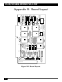
1
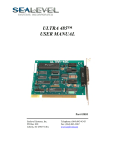
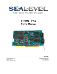
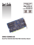
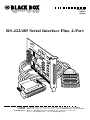
JUNE 2000
IC058C
IC183C
RS-422/485 Serial Interface Plus, 4-Port
CUSTOMER
SUPPORT
INFORMATION
Order toll-free in the U.S. 24 hours, 7 A.M. Monday to midnight Friday: 877-877-BBOX
FREE technical support, 24 hours a day, 7 days a week: Call 724-746-5500 or fax 724-746-0746
Mail order: Black Box Corporation, 1000 Park Drive, Lawrence, PA 15055-1018
Web site: www.blackbox.com • E-mail: [email protected]
RS-422/485 SERIAL INTERFACE PLUS, 4-PORT
TRADEMARKS
All applied-for and registered trademarks are the property of their respective
owners.
Any trademarks mentioned in this manual are acknowledged to be the property of the
trademark owners.
EMC Directive Statement
Products bearing the CE label fulfill the requirements of the EMC directive
(89/336/EEC) and of the low-voltage directive (73/23/EEC) issued by the
European Commission.
To obey these directives, the following European standards must be met:
• EN55022 Class A — “Limits and methods of measurement of radio
interference characteristics of information technology equipment”
• EN50082-1 — “Electromagnetic compatibility — Generic immunity
standard” Part 1: Residential, commercial, and light industry
• EN60950 (IEC950) — “Safety of information technology equipment,
including electrical business equipment”
4
RS-422/485 SERIAL INTERFACE PLUS, 4-PORT
Contents
1. Specifications . . . . . . . . . . . . . . . . . . . . . . . . . . . . . . . . . . . . . . . . . 7
2. Introduction . . . . . . . . . . . . . . . . . . . . . . . . . . . . . . . . . . . . . . . . . . 8
2.1 Overview . . . . . . . . . . . . . . . . . . . . . . . . . . . . . . . . . . . . . . . . 8
2.2 What’s Included . . . . . . . . . . . . . . . . . . . . . . . . . . . . . . . . . . 8
2.3 Factory-Default Settings . . . . . . . . . . . . . . . . . . . . . . . . . . . . 8
2.4 Technical Description . . . . . . . . . . . . . . . . . . . . . . . . . . . . . 9
2.4.1 Features . . . . . . . . . . . . . . . . . . . . . . . . . . . . . . . . . . . . 9
2.4.2 Modem Control Signals . . . . . . . . . . . . . . . . . . . . . . . 10
2.4.3 Interrupts . . . . . . . . . . . . . . . . . . . . . . . . . . . . . . . . . . 10
2.4.4 Why Use an ISP? . . . . . . . . . . . . . . . . . . . . . . . . . . . . . 10
3. Card Setup. . . . . . . . . . . . . . . . . . . . . . . . . . . . . . . . . . . . . . . . . . . . 11
3.1 Address Selection . . . . . . . . . . . . . . . . . . . . . . . . . . . . . . . . . 11
3.2 Jumper Selections . . . . . . . . . . . . . . . . . . . . . . . . . . . . . . . . . 14
3.3 IRQ Selection . . . . . . . . . . . . . . . . . . . . . . . . . . . . . . . . . . . . 14
3.4 Interrupt Modes . . . . . . . . . . . . . . . . . . . . . . . . . . . . . . . . . . 15
3.5 RS-485 Enable Modes . . . . . . . . . . . . . . . . . . . . . . . . . . . . . . 16
3.6 Interface Mode Examples J1D – J4D . . . . . . . . . . . . . . . . . . 18
3.7 Line Termination . . . . . . . . . . . . . . . . . . . . . . . . . . . . . . . . . 20
3.8 Clock Modes . . . . . . . . . . . . . . . . . . . . . . . . . . . . . . . . . . . . . 21
4. Installation . . . . . . . . . . . . . . . . . . . . . . . . . . . . . . . . . . . . . . . . . . . 24
4.1 Software Installation . . . . . . . . . . . . . . . . . . . . . . . . . . . . . . . 24
4.1.1 Windows 3.1x . . . . . . . . . . . . . . . . . . . . . . . . . . . . . . . 24
4.1.2 Windows 95/98 . . . . . . . . . . . . . . . . . . . . . . . . . . . . . . 24
4.1.3 Windows NT . . . . . . . . . . . . . . . . . . . . . . . . . . . . . . . . 24
4.2 Hardware Installation . . . . . . . . . . . . . . . . . . . . . . . . . . . . . . 24
5. Troubleshooting . . . . . . . . . . . . . . . . . . . . . . . . . . . . . . . . . . . . . . . 26
5
RS-422/485 SERIAL INTERFACE PLUS, 4-PORT
Appendix A: Connector Pin Assignments . . . . . . . . . . . . . . . . . . . . 27
Appendix B: Board Layout . . . . . . . . . . . . . . . . . . . . . . . . . . . . . . . . 29
Appendix C: Electrical Interface . . . . . . . . . . . . . . . . . . . . . . . . . . . 30
Appendix D: Asynchronous Communications . . . . . . . . . . . . . . . . 31
6
RS-422/485 SERIAL INTERFACE PLUS, 4-PORT
1. Specifications
Communication Chip — IC058C: 16750 UART; IC183C: 16950 UART
Maximum Distance — 4000 ft. (1219.2 m)
Operation — 2- or 4-wire
Protocol — Asynchronous
Speed — IC058C: Up to 460.8 kbps; IC183C: 460.8 kbps and above
Connectors — (1) DB37 male, (4) DB9 male on included cable
CE Approval — The unit is CE approved
Manufacturing — IPC 610-A Class-III standards are adhered to with an 0.1
visual A.Q.L. and 100% Functional Testing. This printed circuit board is built
to U.L.® 94V0 rating and is 100% electrically tested. This printed circuit board
is solder mask over bare copper or solder mask over tin nickel.
MTBF — Greater than 150,000 hours (calculated)
Temperature — Operating: 32 to 122°F (0 to 50°C);
Storage: -4 to +158°F (-20 to +70°C)
Humidity — 10 to 90% relative humidity, noncondensing
Power — From PC bus: 600 ma @ 5 VDC
Size — Half-card; 4.2”H x 3.9”W 8”D (10.7 x 9.9 x 20.3 cm)
7
RS-422/485 SERIAL INTERFACE PLUS, 4-PORT
2. Introduction
2.1 Overview
The RS-422/485 Serial Interface Plus, 4-Port provides the PC with four
additional RS-422/485 serial ports for terminals, modems, printers, etc. The
Card is RS-485 compatible without special software or drivers. This ability is
especially useful in Windows®, Windows NT, and OS/2® environments where
the lower-level I/O control is abstracted from the application program. This
ability means that you can effectively use the Card in an RS-485 application
with existing standard RS-232 software drivers.
2.2 What’s Included
The Card is shipped with the following items. If any of these items
are missing or damaged, contact the supplier.
• RS-422/485 Serial Interface Plus, 4-Port Card
• DB37 to four DB9 “Spider Cable”
• (2) serial utility software diskettes: (1) for 32-bit Windows®,
(1) for DOS and Windows®3.1x,
• This User’s Manual
2.3 Factory-Default Settings
The factory-default settings are as follows:
Table 2-1. Factory Default Settings.
8
Port #
Base Address
IRQ
Electrical Specifications
Port 1
3F8
4
RS-422
Port 2
2F8
3
RS-422
Port 3
3E8
4
RS-422
Port 4
2E8
3
RS-422
RS-422/485 SERIAL INTERFACE PLUS, 4-PORT
To install the Card using factory-default settings, refer to Chapter 4,
Installation.
For your reference, record installed Card settings below:
Table 2-2. Your Installed Card Settings.
Port #
Base Address
IRQ
Electrical Specifications
Port 1
Port 2
Port 3
Port 4
2.4 Technical Description
The IC058C Card uses the 16750 UART. This chip features programmable
baud rate, data format, and interrupt control, and a 16-byte input and output
FIFO. The IC183C card uses the 16950 UART, which features a 128-byte FIFO
for even better performance.
2.4.1 FEATURES
• Automatic RS-485 driver enable/disable allows card to appear to be
RS-232, requiring no additional drivers
• “PAL” option allows for unique OEM address selection
• “Shareable” IRQs allow more than one port to share a single IRQ
• IRQs 2/9-7, 10, 11, 12, 15 supported
• 16750 buffered UARTs (IC058C) or 16950 UARTs (IC183C)
• 16 Bit address decode allows for easier integration
• Speeds up to 460.8 kbps available
• Multiple clocking modes ensure compatibility with existing software
products
9
RS-422/485 SERIAL INTERFACE PLUS, 4-PORT
2.4.2 MODEM CONTROL SIGNALS
Some software packages require the use of modem handshake signals such as
CTS or DCD. Refer to your application software manual to determine the
requirements for modem control signals. If no requirements are mentioned,
a safe configuration is to tie DTR to DSR and DCD, and tie RTS to CTS. This
configuration will typically satisfy the modem control-signal requirements for
most communications software.
2.4.3 INTERRUPTS
A good analogy of a PC interrupt would be a phone ringing. The phone “bell”
is a request for us to stop what we are currently doing and take up another
task (speak to the person on the other end of the line). This is the same
process the PC uses to alert the CPU that a task must be performed. The CPU,
upon receiving an interrupt, makes a record of what the processor was doing
at the time and stores the information in the “stack”; this allows the processor
to resume its predefined duties after the interrupt is handled, exactly where it
left off. Every main subsystem in the PC has its own interrupt, frequently
called an IRQ (short for Interrupt ReQuest).
2.4.4 WHY USE AN ISP?
An Interrupt Status Port (ISP) is a read-only, 8-bit register that sets a
corresponding bit when an interrupt is pending. Port 1 interrupt line
corresponds with Bit D0 of the status port, Port 2 with D1, etc. The use of this
port means that the software designer now only has to poll a single port to
determine if an interrupt is pending.
The ISP is at Base+7 on each port (Example: Base=280 Hex, Status
Port=287, 28F...etc.). The RS-422/485 Serial Interface Plus Card will allow any
one of the available locations to be read to obtain the value in the status port.
All four status ports on the Card are identical, so any one of the four can be
read.
Example: This indicates that Port 2 has an interrupt pending.
Bit Position:
Value Read:
10
7
0
6
0
5
0
4
0
3
0
2
0
1
1
0
0
RS-422/485 SERIAL INTERFACE PLUS, 4-PORT
3. Card Setup
The RS-422/485 Serial Interface Plus, 4-Port Card has several jumper straps
which must be set for proper operation.
3.1 Address Selection
Each port on the Card occupies eight consecutive I/O locations. A DIP switch
is used to set the base address for these locations. The Card has a unique
addressing scheme that allows it to be completely compatible with older four
port RS-422/485 interface adapters and provide for the ability to select
address combinations more commonly used.
The first addressing scheme allows the Card to select the addresses for its
ports from a table of available address combinations.
Table 3-1 shows the addressing combinations available. If different address
combinations are required, please contact Technical Support about a custom
PAL option.
11
RS-422/485 SERIAL INTERFACE PLUS, 4-PORT
Table 3-1. Available Address Combinations.
Switch 6
Switch 7
Switch 8 Port 1
Port 2
Port 3
Port 4
On
On
Off
3F8
2F8
3E8
2E8
On
Off
On
2F8
3E8
2E8
2E0
On
Off
Off
3E8
2E8
280
288
Off
On
On
500
508
510
518
Off
On
Off
580
588
590
598
Off
Off
On
1500
1508
1510
1518
Off
Off
Off
3220
3228
4220
4228
On
On
On
Addresses set up by switches 1-5
NOTE
Each COM: port in the system should have a unique address. Typically COM 1: COM4: addresses are 3F8, 2F8, 3E8, and 2E8 Hex.
Refer to Chapter 5 for common address contentions.
The second mode of address selection provides the compatibility mode. In
this mode, the DIP switch sets the base address and the adapter occupies 32
consecutive I/O locations. Table 3-2 describes the location of each port and
its relationship to the other ports.
NOTE
For switches 1-5 to become active, switches 6, 7, and 8 must be set in the “On” or
“Up” position.
12
RS-422/485 SERIAL INTERFACE PLUS, 4-PORT
Table 3-2. Address Selection Table.
Address lines
A9
A8
A7
A6
A5
Address Selected 1
2
3
4
5
280-29F
Off
On
Off
On
On
2A0-2BF
Off
On
Off
On
Off
380-39F
Off
Off
Off
On
On
1A0-1BF
On
Off
Off
On
Off
2E0-2FF
Off
On
Off
Off
Off
Figure 3-1 shows the correlation between the DIP-switch setting and the
address bits used to determine the base address. In the example below,
address 2E0 is selected as a base. Address 2E0 in binary is XX 10 111X XXXX
where X = a non-selectable address bit.
A9
A5
ON
OFF
1 2 3 4 5 6 7 8
Figure 3-1. DIP Switch Setting.
13
RS-422/485 SERIAL INTERFACE PLUS, 4-PORT
Table 3-3. Port to Connector Table.
Port #
Connector Location
Address
Example (Base=2E0)
1
1
Base+0
2E0-2E7
2
2
Base+8
2E8-2EF
3
3
Base+16
2F0-2F7
4
4
Base+24
2F8-2FF
3.2 Jumper Selections
For ease of configuration, the headers are grouped by port. Port 1 headers
have a “J1” prefix, Port 2 headers have the “J2” prefix, etc. For example, the
header that controls the Port 1 IRQ selection is J1B, the header that controls
the Port 2 IRQ selection is J2B. Information for configuring the adapter is
printed directly on the Card. This is particularly useful in field reconfiguration.
3.3 IRQ Selection
Headers J1B through J4B select the interrupt request for each serial port. If
COM1: is selected, the corresponding jumper must be on the IRQ4 setting. If
COM2: is selected, the corresponding jumper must be on IRQ3.
NOTE
Most communications software applications default COM3: to IRQ4 and COM4:
to IRQ3. This requires the sharing of interrupts between COM1: and COM3:,
and between COM2: and COM4:. While this is the default, it is not always the
best setting. Check your software configuration instructions to determine the
most appropriate IRQ selection.
14
RS-422/485 SERIAL INTERFACE PLUS, 4-PORT
3 4 5 6 7 9 10 11 12 15
Figure 3-2. Headers J1B – J4B, IRQ Selection.
Any two or more ports can share a common IRQ by placing the jumpers on
the same IRQ setting and setting the appropriate selections at J1A through
J4A. Consult your particular software for IRQ selection. If no interrupt is
desired, remove the jumper.
3.4 Interrupt Modes
Headers J1A through J4A select the interrupt modes for each port. Each port
must be set in the correct mode to ensure proper operation.
“N” indicates the (N)ormal, single-interrupt-per-port mode. “S” indicates
the (S)hared interrupt mode, which allows more than one port to access a
single IRQ. ‘M’ indicates the inclusion of a 1-Kohm pull-down resistor
required on one port when sharing interrupts.
J1A
N
S
M
Figure 3-3. Header J1A, Normal IRQ Mode.
15
RS-422/485 SERIAL INTERFACE PLUS, 4-PORT
Set the jumpers to “S” for shared interrupt mode on all blocks sharing an
IRQ except one. Set that port block for “M.” This provides the pull-down
resistor circuit that makes sharing IRQs possible. If you are using more than
one Serial Interface Plus Card or a compatible adapter in a bus you should
only have one port set to “M.” Figure 3-4 shows two ports sharing a single IRQ.
J1A
N
S
M
N
S
M
J2A
Figure 3-4. Header J1A & J2A, Shared IRQ Mode.
Set the jumper to “S” if you are using more than one Card in a bus or to
completely remove the pull-down resistor for hardware compatibility. Setting
the adapter in this configuration when it is not accompanied by a pull-down resistor
will prevent the ports from triggering an interrupt.
16
RS-422/485 SERIAL INTERFACE PLUS, 4-PORT
3.5 RS-485 Enable Modes
RS-485 is ideal for multi-drop or network environments. RS-485 requires a tristate driver (not dual-state) that will allow the electrical presence of the driver
to be removed from the line. The driver is in a tri-state or high-impedance
condition when this occurs. Only one driver may be active at a time and the
other driver(s) must be tri-stated. The output modem control signal Request
To Send (RTS) is typically used to control the state of the driver. Some
communication software packages refer to RS-485 as RTS enable or RTS
block-mode transfer.
One of the unique features of the Serial Interface Plus Card is the ability to
be RS-485 compatible without the need for special software or drivers. This
ability is especially useful in Windows, Windows NT, and OS/2 environments
where the lower-level I/O control is abstracted from the application program.
This ability means that you can effectively use the Card in an RS-485
application with existing standard RS-232 software drivers.
Headers J1D through J4D are used to control the RS-485 mode functions
for the driver circuit. The selections are “RTS” enable (silk-screen “RT”) or
“Auto” enable (silk-screen “AE”). The “Auto” enable feature automatically
enables/disables the RS-485 interface. The “RTS” mode uses the “RTS”
modem control signal to enable the RS-485 interface and provides backward
compatibility with existing software products.
Position 3 (silk-screen “NE”) of J1D through J4D is used to control the RS485 enable/disable functions for the receiver circuit and determine the state
of the RS-422/485 driver. The RS-485 “Echo” is the result of connecting the
receiver inputs to the transmitter outputs. Every time a character is
transmitted, it is also received. This can be beneficial if the software can
handle echoing using received characters to throttle the transmitter or it can
confuse the system if the software does not. To select the “No Echo” mode
select silk-screen position “NE.”
For RS-422/530/449 compatibility, remove the jumpers at J1D through J4D.
Examples on the following pages describe all of the valid settings for
J1D-J4D.
17
RS-422/485 SERIAL INTERFACE PLUS, 4-PORT
AT
RT
NE
3.6 Interface Mode Examples J1D – J4D
AT
RT
NE
Figure 3-5. Headers J1D - J4D, RS-422.
Figure 3-6. Headers J1D - J4D, RS-485 “Auto” Enabled,
with “No Echo.”
18
AT
RT
NE
RS-422/485 SERIAL INTERFACE PLUS, 4-PORT
AT
RT
NE
Figure 3-7. Headers J1D - J4D, RS-485 “Auto” Enabled, with “Echo.”
Figure 3-8. Headers J1D - J4D, RS-485 “RTS” Enabled,
with “No Echo.”
19
AT
RT
NE
RS-422/485 SERIAL INTERFACE PLUS, 4-PORT
Figure 3-9. Headers J1D - J4D, RS-485 “RTS” Enabled, with “Echo.”
3.7 Line Termination
Typically, each end of the RS-485 bus must have line-terminating resistors
(RS-422 terminates at the receive end only). A 120-ohm resistor is across each
RS-530/422/485 input in addition to a 1-Kohm pull-up/pull-down
combination that bias the receiver inputs. Headers J1E through J4E allow the
user to customize this interface to their specific requirements. Each jumper
position corresponds to a specific portion of the interface. If multiple Serial
Interface Plus adapters are configured in a RS-485 network, only the boards
on each end should have jumpers T, P, and P ON. Refer to the table on the
next page for each position’s operation:
P
P
T
L
L
Figure 3-10. Headers J1E - J4E, Line Termination.
20
RS-422/485 SERIAL INTERFACE PLUS, 4-PORT
Table 3-4. Jumper Functions.
Name
Function
P
Adds or removes the 1-Kohm pull-down resistor in the
RS-422/RS-485 receiver circuit (Receive data only).
P
Adds or removes the 1-Kohm pull-up resistor in the
RS-422/RS-485 receiver circuit (Receive data only).
T
Adds or removes the 120-ohm termination.
L
Connects the TX- to RX- for RS-485 two-wire operation.
L
Connects the TX+ to RX+ for RS-485 two-wire operation.
3.8 Clock Modes
The Serial Interface Plus Card employs a unique clocking option that allows
the user to select from divide by 4, divide by 2, and divide by 1 clocking
modes. These modes are selected at Headers J1C through J4C.
To select the baud rates commonly associated with COM: ports (2400,
4800, 9600, 19.2, and so on up to 115.2 kbps ) place the jumper in the “divide
by 4” mode (silk-screen DIV4).
21
DIV1
DIV2
DIV4
RS-422/485 SERIAL INTERFACE PLUS, 4-PORT
Figure 3-11. Clocking Mode “Divide By 4.”
DIV1
DIV2
DIV4
To double these rates up to a maximum rate for 230.4 kbps, place the jumper
in the “divide by 2” (silk-screen DIV2) position.
Figure 3-12. Clocking Mode “Divide By 2.”
To select the maximum data rate (460.8 kbps) place the jumper in the
“divide by 1” (silk-screen DIV1) position.
22
DIV1
DIV2
DIV4
RS-422/485 SERIAL INTERFACE PLUS, 4-PORT
Figure 3-13. Clocking Mode “Divide By 1.”
23
RS-422/485 SERIAL INTERFACE PLUS, 4-PORT
4. Installation
IMPORTANT
You MUST set up the operating system BEFORE you physically install
the Card.
4.1 Software Installation
If you are installing an ISA adapter in DOS, OS/2, or QNX, please refer to the
appropriate directory on one of the Serial Utilities Disks for instructions.
4.1.1 WINDOWS 3.1X
Please refer to the /WINDOWS sub-directory on the Serial Utilities Diskette
for help files and current information on the installation of the Card in
thisoperating environment.
4.1.2 WINDOWS 95/98 USERS
For the ISA card, run setup on disk two of the Serial Utilities Diskettes before
installing the card. Make note of the resources that Windows assigns the adapter
and set the adapter to match those resources. Power down the computer and
install the adapter as described in Section 4.2. If you wish to change any resources
assigned to the adapter, refer to the help file installed in the Black Box folder in
the Start, Programs menu.
4.1.3 WINDOWS NT
For the ISA card, run setup on disk two of the Serial Utilities Diskettes before
installing the card. After installing the software, refer to the help file that
automatically comes up for installation instructions.
24
RS-422/485 SERIAL INTERFACE PLUS, 4-PORT
4.2 Hardware Installation
The RS-422/485 Serial Interface Plus Card can be installed in any of the PC
expansion slots. The Card contains several jumper straps for each port that
you must set for proper operation.
1. Turn off PC power. Disconnect the power cord.
2. Remove the PC case cover.
3. Locate an available slot and remove the blank metal slot cover.
4. Gently insert the Card into the slot. Make sure that the Card is seated
properly.
5. Replace the screw.
6. Replace the cover.
7. Connect the power cord.
Installation is complete.
25
RS-422/485 SERIAL INTERFACE PLUS, 4-PORT
5. Troubleshooting
Two Serial Utility Diskettes are supplied with the adapter and will be used in
the troubleshooting procedures. By using this diskette and following these
simple steps, most common problems can be eliminated. If you still cannot
solve your problem, call Black Box technical support at 724-746-5500.
1. Identify all I/O adapters currently installed in your system. This includes
your on-board serial ports, controller cards, sound cards etc. The I/O
addresses used by these adapters, as well as the IRQ (if any) should be
identified.
2. Configure your RS-422/485 Serial Interface Plus Card so that there is no
conflict with currently installed adapters. No two adapters can occupy the
same I/O address.
3. Make sure the adapter is using a unique IRQ. While the adapter does
allow the sharing of IRQs, many other adapters (such as SCSI adapters
and on-board serial ports) do not. The IRQ is typically selected via an onboard header block. Refer to the section on Card Setup for help in
choosing an I/O address and IRQ.
4. Make sure the adapter is securely installed in a motherboard slot.
5. Use the supplied diskette and User Manual to verify that the adapter is
configured correctly. The supplied diskette contains a diagnostic program
“SSD” that will verify if an adapter is configured properly. This diagnostic
program is written with the user in mind and is easy to use. Refer to the
“README” file on the supplied diskette for detailed instructions on using
“SSD.”
26
RS-422/485 SERIAL INTERFACE PLUS, 4-PORT
6. The following are known I/O conflicts:
• The 278 and 378 settings may conflict with your printer I/O adapter.
• 3B0 cannot be used if a Monochrome adapter is installed.
• 3F8-3FF is typically reserved for COM1:
• 2F8-2FF is typically reserved for COM2:
• 3E8-3EF is typically reserved for COM3:
• 2E8-2EF is typically reserved for COM4:
7. Please refer to your included diskette for any post production manual
updates and application specific information.
8. Always use the included diagnostic software when troubleshooting a
problem. This will eliminate the software issue from the equation.
27
RS-422/485 SERIAL INTERFACE PLUS, 4-PORT
Appendix A: Connector Pin Assignments
Table A-1. DB9 Pin Assignments.
28
Signal
Name
Pin #
Mode
GND
Ground
5
TX+
Transmit Data Positive
4
Output
TX-
Transmit Data Negative
3
Output
RTS+
Request to Send Positive
6
Output
RTS-
Request to Send Negative
7
Output
RX+
Receive Data Positive
1
Input
RX-
Receive Data Negative
2
Input
CTS+
Clear to Send Positive
9
Input
CTS-
Clear to Send Negative
8
Input
RS-422/485 SERIAL INTERFACE PLUS, 4-PORT
Table A-2. DB37 Pin Assignments.
Port #
1
2
3
4
GND
33
14
24
5
TX-
35
12
26
3
RTS-
17
30
8
21
TX+
34
13
25
4
RX-
36
11
27
2
CTS-
16
31
7
22
RTS+
18
29
9
20
RX+
37
10
28
1
CTS+
15
32
6
23
29
RS-422/485 SERIAL INTERFACE PLUS, 4-PORT
Appendix B: Board Layout
Y1
C1
R1
D1
R2
D2
R3
D3
R4
D4
R5
3 4 5 6 7 9 10 11 12 15
N S M
3 4 5 6 7 9 10 11 12 15
N S M
3 4 5 6 7 9 10 11 12 15
N S M
U1 74LS74
PORT1= J1x
PORT2= J2x
PORT3= J3x
PORT4= J4x
J1A
J1B
J2A
J2B
J3A
J3B
N S M
3 4 5 6 7 9 10 11 12 15
J1C
J2C
J3C
J4C
C4
+
C5
U4
C7
U7
C9
RP1 MACH215
RP2
SWITCH8DIP
U8
U9
C12
MACH215
J1D
J4D
J3D
J2D
SW1
C10
74HC04
75175
U13 75174
U12
RP3
U11
R6
R7
R8
R9
U16
74LS245
C14
C15
C17
RP4
R10
75175
R11
U14
C16
R12
R13
U15 75174
* JxD JUMPER SETTINGS *
RS422= REMOVE ALL JUMPERS
RS485-AT= AUTO ENABLE
RS485-RT= RTS ENABLE
RS485-NE= NO ECHO
C13
74LS244
U10
J1E
P
P
T
L
L
P
P
T
L
L
P
P
T
L
L
P3
* JxE JUMPER SETTINGS *
P= PULL UP/DOWN ENABLE
T= TERMINATION ENABLE
L= CONNECT RX TO TX
J2E
J3E
J4E
P
P
T
L
L
Figure B-1. Board Layout.
* JxA= INT MODE SELECT *
* JxC= CLOCK DIV SELECT *
N= NORMAL INT MODE
DIV1= CLOCK DIVIDE BY 1
S= SHARED INT MODE
DIV2= CLOCK DIVIDE BY 2
M= SHARED WITH RESISTOR DIV4= CLOCK DIVIDE BY 4
* JxB= INT SELECT *
U2
16550 PORT2
C8
16550 PORT4
U6
U5 74HC125
C5
16550 PORT1
U3
16550 PORT3
P1
XC7336-3440
C11
30
J4A
J4B
P2
SD837M-318
R14
R15
R16
R17
AT
RT
NE
AT
RT
NE
AT
RT
NE
AT
RT
NE
A9
A8
A7
A6
A5
S3
S2
S1
C2
C3
DIV1
DIV2
DIV4
DIV1
DIV2
DIV4
DIV1
DIV2
DIV4
DIV1
DIV2
DIV4
RS-422/485 SERIAL INTERFACE PLUS, 4-PORT
Appendix C: Electrical Interface
RS-422
The RS-422 specification defines the electrical characteristics of balancedvoltage digital interface circuits. RS-422 is a differential interface that defines
voltage levels and driver/receiver electrical specifications. On a differential
interface, logic levels are defined by the difference in voltage between a pair
of outputs or inputs. In contrast, a single-ended interface, for example RS232, defines the logic levels as the difference in voltage between a single
signal and a common ground connection. Differential interfaces are typically
more immune to noise or voltage spikes that may occur on the
communication lines. Differential interfaces also have greater drive
capabilities that allow for longer cable lengths. RS-422 is rated up to 10
Megabits per second and can have cabling 4000 feet (1219 m) long.
RS-422 also defines driver and receiver electrical characteristics that will allow
1 driver and up to 32 receivers on the line at once. RS-422 signal levels range
from 0 to +5 volts. RS-422 does not define a physical connector.
RS-485
RS-485 is backward-compatible with RS-422; however, it is optimized for
partyline or multi-drop applications. The output of the RS-422/485 driver is
capable of being Active (enabled) or Tri-State (disabled). This capability
allows multiple ports to be connected in a multi-drop bus and selectively
polled. RS-485 allows cable lengths up to 4000 feet (1219 m) and data rates
up to 10 Megabits per second. The signal levels for RS-485 are the same as
those defined by RS-422. RS-485 has electrical characteristics that allow for 32
drivers and 32 receivers to be connected to one line. This interface is ideal for
multi-drop or network environments. RS-485’s tri-state driver (not dual-state)
will allow the electrical presence of the driver to be removed from the line.
Only one driver may be active at a time and the other driver(s) must be tristated. RS-485 can be cabled in two ways, two-wire and four-wire mode. Twowire mode does not allow for full-duplex communication, and requires that
data be transferred in only one direction at a time. For half-duplex operation,
the two transmit pins should be connected to the two receive pins (Tx+ to
Rx+ and Tx- to Rx-). Four-wire mode allows full-duplex data transfers. RS-485
does not define a connector pin-out or a set of modem control signals. RS-485
does not define a physical connector.
31
RS-422/485 SERIAL INTERFACE PLUS, 4-PORT
Appendix D: Asynchronous
Communications
In serial data communications, individual bits of a character are transmitted
consecutively to a receiver that assembles the bits back into a character. Data
rate, error checking, handshaking, and character framing (start/stop bits) are
pre-defined and must correspond at both the transmitting and receiving ends.
Asynchronous communications is the standard means of serial data
communication for PC compatibles and PS/2® computers. The original PC
was equipped with a communication or COM: port that was designed around
an 8250 Universal Asynchronous Receiver Transmitter (UART). This device
allows asynchronous serial data to be transferred through a simple and
straightforward programming interface. Character boundaries for
asynchronous communications are defined by a starting bit followed by a predefined number of data bits (5, 6, 7, or 8). The end of the character is
defined by the transmission of a pre-defined number of stop bits (usual
1, 1.5 or 2).
Idle state of
line
Odd, Even
or
Unused
Remain idle or
next start bit
5 to 8 Data Bits
1
P
BIT
STOP
0
1
1.5
2
Figure D-1. Asynchronous Communications Bit Diagram.
32
RS-422/485 SERIAL INTERFACE PLUS, 4-PORT
An extra bit used for error detection is often appended before the stop bits.
This special bit is called the parity bit. Parity is a simple method of
determining if a data bit has been lost or corrupted during transmission.
There are several methods for implementing a parity check to guard against
data corruption. Common methods are called (E)ven Parity and (O)dd
Parity. Sometimes parity is not used to detect errors on the data stream. This
is refereed to as (N)o parity. Because each bit in asynchronous
communications is sent consecutively, it is easy to generalize asynchronous
communications by stating that each character is wrapped (framed) by predefined bits to mark the beginning and end of the serial transmission of the
character. The data rate and communication parameters for asynchronous
communications have to be the same at both the transmitting and receiving
ends. The communication parameters are baud rate, parity, number of data
bits per character, and stop bits (for example, 9600,N,8,1).
33
© Copyright 2000. Black Box Corporation. All rights reserved.
1000 Park Drive
•
Lawrence, PA 15055-1018
•
724-746-5500
•
Fax 724-746-0746