1
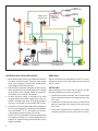
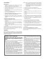
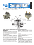
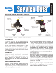
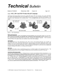
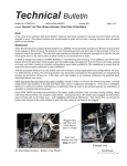
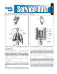
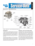
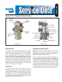
SD-03-3652
Bendix® TP-3® Tractor Protection Valve
TRACTOR
EMERGENCY
PORT
TRAILER
EMERGENCY
PORT
O-RING(13)
PLUNGER(11)
INLET VALVE(4)
TRAILER
SERVICE
PORT
TRACTOR
SERVICE
PORT
VALVE RETAINER(10)
RETAINING RING(2)
O-RING(12)
VALVE SPRING(6)
DIAPHRAGM
SEAT(9)
SEAT
DIAPHRAGM(5)
WASHER(8)
EXTERIOR VIEW
O-RING(7)
RETAINING RING(1)
CAP SCREW(3)
CROSS SECTION
FIGURE 1 - BENDIX® TP-3® TRACTOR PROTECTION VALVE
DESCRIPTION
PREVENTIVE MAINTENANCE
The Bendix® TP-3® Tractor Protection Valve is used in
combination with the Bendix® PP-3™ Trailer Supply Valve
on pre-121 tractors, and the Bendix® PP-7™ Trailer Supply
Valve, or the Bendix® MV-3® Valve, on post-121 tractors. It
contains a passage for trailer supply air and a service line
shut off valve. It is normally mounted behind the cab, with
the delivery line from the trailer supply valve connected
into the tractor emergency port and a delivery line from the
brake valve connected to the tractor service port. The trailer
supply and service hoses are mounted in their respective
ports in the TP-3 valve. See Figure 2.
Important: Review the Bendix Warranty Policy before
performing any intrusive maintenance procedures. A
warranty may be voided if intrusive maintenance is
performed during the warranty period.
OPERATION
Air from the trailer supply valve passes through the
emergency ports of the TP-3 valve to supply the trailer air
system and simultaneously exerts pressure on the end of
the plunger(11). The TP-3 valve requires approximately 45
psi to open the inlet valve. Whenever the pressure from
the trailer supply valve drops below 45 psi, the TP-3 valve
will close the service line shut-off valve.
No two vehicles operate under identical conditions; as
a result, maintenance intervals may vary. Experience is
a valuable guide in determining the best maintenance
interval for air brake system components. At a minimum,
the Bendix TP-3 valve should be inspected every 6 months
or 1500 operating hours, whichever comes first, for proper
operation. Should the TP-3 valve not meet the elements
of the operational tests noted in this document, further
investigation and service of the valve may be required.
1
TRAILER
EMERGENCY LINE
BENDIX TP-3
TRACTOR
PROTECTION
VALVE
®
BENDIX® MV-3®
CONTROL VALVE
®
TRAILER
SERVICE LINE
DOUBLE
CHECK
VALVE
BRAKE
VALVE
AIR
DRYER
FRONT
RESERVOIR
REAR
RESERVOIR
COMPRESSOR
FIGURE 2 - SYSTEM SCHEMATIC
OPERATING AND LEAKAGE CHECKS
REMOVING
1. Block and/or hold the vehicle by a means other than the
air brakes during these tests. Place the trailer supply
valve in the emergency position and disconnect the
trailer supply and service couplings.
Remove the trailer hose assemblies from the TP-3 valve.
Disconnect tractor service and supply lines and remove
the TP-3 valve.
2. With the tractor reservoirs charged to at least 100 psi,
make and hold a full service brake application. Leakage
at either tractor hose coupling should not exceed a 1
inch bubble in five seconds (100 SCCM).
INSTALLING
3. Connect the trailer supply, or emergency line, hose
coupling and place the trailer supply valve in the “run”
position. Leakage at the “service” coupling should not
exceed a 1 inch bubble in five seconds (100 SCCM).
4. Connect the service coupling and make and hold a full
service brake application: Leakage at the diaphragm
end of the Bendix ® TP-3 ® Valve shall not exceed a
1 inch bubble in three seconds (175 SCCM).
NOTE: If the TP-3 Valve does not function as described,
or if leakage is excessive, it is recommended that it be
replaced or repaired using genuine Bendix service
replacement parts.
2
When installing the TP-3 valve, refer to Figure 2, and the
following explanation, for proper connections.
1. The delivery line from the Bendix® MV-3® Dash Control
Valve is connected to the tractor emergency port of the
TP-3 valve.
2. The delivery line from the brake valve (or double check
valve) is connected to the tractor service port of the
TP-3 valve.
3. Trailer hose assemblies are installed in the trailer
emergency and trailer service ports of the TP-3 valve.
DISASSEMBLY
(See Figure 1.)
1. Remove the diaphragm seat retainer ring (1) while
holding the diaphragm seat (9) in the body.
2. While still holding the diaphragm seat in the body,
remove the date code ring.
3. Allow the seat to rise until the valve spring force is no
longer present.
NOTE: When using pipe thread sealant during assembly
and installation, take particular care to prevent the
sealant from entering the valve itself. Apply the
sealant beginning with the second thread back
from the end.
1. Install the inlet valve (4) on the plunger (11).
2. Position and force the valve retainer (10) down over
the inlet valve.
4. Remove the diaphragm seat assembly (9), valve spring
(6), and plunger assembly (11).
3. Install the retainer ring (2) beneath the inlet valve
retainer.
5. Remove the diaphragm seat o-ring (7), cap screw (3),
diaphragm washer (8) and diaphragm (5).
4. Install both plunger o-rings (12) and (13) in their proper
grooves.
6. Remove the valve retainer ring (2), valve retainer
(10), inlet valve (4), and o-rings (12) and (13) from the
plunger.
5. Place the plunger and valve assembly in the valve body.
CLEANING AND INSPECTION
6. Install the cap head screw (3), diaphragm washer
(8) with the cup side up, and diaphragm (5) into the
diaphragm seat (9).
1. Clean all metal parts in mineral spirits and dry them
completely.
7. Place the inlet valve spring (6) into the plunger.
2. Inspect all parts for excessive wear or deterioration.
Inspect valve seats for nicks or burrs. Check the valve
spring for cracks or corrosion.
9. Position the diaphragm seat assembly over the spring
and plunger assembly and force it into the body.
3. Inspect the bores of the valve housing for deep scuffing
or gouges.
Replace all parts that were discarded, and any parts not
found to be serviceable during inspection, using only
genuine Bendix® replacement parts.
ASSEMBLY
8. Install the diaphragm seat o-ring (7) in the body.
10. Replace the date code washer and install the retaining
ring (1) making sure the retaining ring snaps fully into
the groove.
TESTING SERVICED BENDIX TP-3 VALVES
Perform the operating and leakage checks as outlined in
previous section.
Before assembling the Bendix® TP-3® Tractor Protection
Valve, lubricate all o-rings, o-ring grooves, body bores and
rubbing surfaces with Bendix silicone lubricant (Piece No.
291126) or equivalent.
3
BW1572 © 2012 Bendix Commercial Vehicle Systems LLC, a member of the Knorr-Bremse Group • 9/2012 • All rights reserved..
4