1
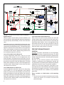
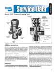
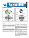
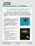
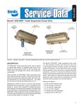
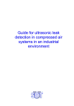
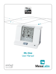
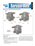
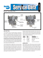
SD-03-1000
Bendix® Dual Relay Valve
PRIMARY
CONTROL
PORT (41)
DELIVERY
PORT (22)
RESERVOIR
SUPPLY
PORT (11)
RESERVOIR
SUPPLY
PORT (11)
MOUNTING
BRACKET STUDS
CAST PORT
IDENTIFICATION
SECONDARY
CONTROL
PORT (42)
EXHAUST
PORT (1)
FIGURE 1 - DUAL RELAY VALVE
DESCRIPTION
The Dual Relay Valve is a special purpose, multifunction
relay valve. It is typically used on articulated vehicles with
three or more axles. Normally mounted at the rear of the
vehicle, in proximity to the valves and chambers served, its
function is similar to a pilot relay and speeds the application
and release of control air pressure to the service relay
valve(s) on the rear most axle or axles of the vehicle. The
Dual Relay Valve is a pilot relay valve that responds to the
control air delivered to it from both circuits of the foot brake
valve. The Dual Relay Valve is controlled independently
by the front (secondary) and mid (primary) delivery circuits
of the dual circuit foot brake valve.
The Dual Relay Valve is supplied air from the rear axle(s)
service reservoir that is isolated from the other service
reservoirs forming a third service brake circuit on the
vehicle. With the addition of a third brake circuit the vehicle
will maintain braking on at least two axles in the event of a
single service system malfunction. In systems where this
valve is used, the brake circuits are designated as Front
(steering) Axle, Mid-Axle and Rear Axle.
Although typically nipple mounted to the rear service
reservoir the valve can be bracket mounted. Only four (4)
ports are utilized in the die cast body of the Dual Relay
Valve. All air connections are identified with raised numerals
with the following designations:
Port ID
Size
Designation
41
3/8 NPTF
Primary Control Port
42
3/8 NPTF
Secondary Control Port
12, 43
Plugged
Not used
22
3/8 NPTF
Delivery
11
3/8 NPTF
Rear Service Reservoir
OPERATION
Refer to figures 1 and 2. Each service reservoir is isolated
and is protected from loss of air in other service reservoirs.
The front and mid-axle service reservoirs supply air directly
to the secondary and primary circuits of the foot brake
valve, as well as antilock and traction components for their
respective circuits. The rear axle service reservoir supplies
air to the Dual Relay Valve, as well as the rear axle service
antilock relay and traction components.
1
AD-IS EP
EXTENDED PURGE
AIR DRYER
PP-DC™
PUSH-PULL VALVE WITH
INTEGRAL DOUBLE CHECK
TO ACCESSORIES
BVA-85™
DOOR
INTERLOCK
VALVE WITH
CONTROL
MODULE
DUAL
RELAY VALVE
BA-922 ®
TWIN CYLINDER
COMPRESSOR
Secondary
Control
REAR
Primary
Control
ABS-6
WITH
TRACTION CONTROL
FAM
FRONT AXLE
MODULE
FRONT
RAM
REAR AXLE MODULE
MID
FIGURE 2 - TYPICAL ARTICULATED COACH SCHEMATIC
System Normal
Loss of Rear Axle Service Reservoir
With the system normal and air pressure available in all
service reservoirs, brake application pressure is transmitted
from the primary and secondary circuits of the foot brake
valve.
With a loss of rear axle service pressure, the front and
mid-axle brakes will be applied by the foot brake valve.
Primary and secondary control pressure is received by the
Dual Relay Valve however, a no or low application of the
rear brakes will occur due to a loss of pressure in the rear
service reservoir. Front and mid-axle brakes will release
when foot brake valve pressure is removed.
Application pressure is transmitted simultaneously to the
front and mid-axle brakes and to the primary and secondary
control ports of the Dual Relay Valve. The Dual Relay Valve
applies or releases the rear axle brakes in direct proportion
to the control signals received from the foot brake valve.
The brake on each axle are applied using pressure from
their dedicated respective reservoirs.
Loss of Front Axle Service Reservoir
A service application made with a loss of air in the
secondary circuit results in a no or low application of the
front axle brakes. Air pressure from the primary circuit of
the foot brake valve applies the mid-axle brakes and enters
the primary control port of the Dual Relay Valve. The Dual
Relay Valve responds to primary control and applies the
rear axle brakes. Brake release occurs when foot brake
valve pressure is removed.
Loss of Mid-Axle Service Reservoir
A service application made with a loss of air in the primary
circuit results in a no or low application of the mid-axle
brakes. Air pressure from the secondary circuit of the foot
brake valve applies the front axle brakes and enters the
secondary control port of the Dual Relay Valve. The Dual
Relay Valve responds to secondary control and applies the
rear axle brakes. Brake release occurs when foot brake
valve pressure is removed.
2
PREVENTIVE MAINTENANCE
GENERAL
Important: Preventive maintenance for the Dual Relay
Valve consists entirely of inspections and tests. The Dual
Relay Valve is not serviceable and must be replaced when
testing or inspection warrants it. Kits and replacement parts
are not available.
Because no two vehicles operate under identical
conditions, maintenance and maintenance intervals will
vary. Experience is a valuable guide in determining the best
maintenance interval for any one particular operation.
Perform the tests and inspections presented at the
prescribed intervals. If the Dual Relay Valve fails to function
as described or leakage is excessive, it must be replaced
with a genuine Bendix unit, available at any authorized
parts outlet.
Every 3 months, or 25,000 miles or 900 operating
hours:
1. Remove any accumulated contaminants and visually
inspect the exterior for excessive corrosion and
physical damage.
2. Inspect all air lines connected to the Dual Relay Valve
for signs of wear or physical damage. Replace as
necessary.
3. Test air line fittings for excessive leakage and tighten
or replace as necessary.
4. Perform the Leakage Test described in this manual.
Every year, 100,000 miles, or 3,600 operating hours:
1. Perform the Operation and Leakage Tests described
in this manual.
GENERAL SAFETY GUIDELINES
WARNING! PLEASE READ AND FOLLOW
THESE INSTRUCTIONS TO AVOID PERSONAL
INJURY OR DEATH:
When working on or around a vehicle, the
following general precautions should be observed
at all times.
1. Park the vehicle on a level surface, apply the parking
brakes, and always block the wheels. Always wear
safety glasses.
2. Stop the engine and remove ignition key when working
under or around the vehicle. When working in the engine
compartment, the engine should be shut off and the
ignition key should be removed. Where circumstances
require that the engine be in operation, EXTREME
CAUTION should be used to prevent personal injury
resulting from contact with moving, rotating, leaking,
heated or electrically charged components.
3. Do not attempt to install, remove, disassemble or
assemble a component until you have read and
thoroughly understand the recommended procedures.
Use only the proper tools and observe all precautions
pertaining to use of those tools.
4. If the work is being performed on the vehicle’s air brake
system, or any auxiliary pressurized air systems, make
certain to drain the air pressure from all reservoirs
before beginning ANY work on the vehicle. If the
vehicle is equipped with an AD-IS® air dryer system or
a dryer reservoir module, be sure to drain the purge
reservoir.
5. Following the vehicle manufacturer’s recommended
procedures, deactivate the electrical system in a
manner that safely removes all electrical power from
the vehicle.
8. Use only genuine Bendix ® replacement parts,
components and kits. Replacement hardware, tubing,
hose, fittings, etc. must be of equivalent size, type
and strength as original equipment and be designed
specifically for such applications and systems.
9. Components with stripped threads or damaged parts
should be replaced rather than repaired. Do not
attempt repairs requiring machining or welding unless
specifically stated and approved by the vehicle and
component manufacturer.
10. Prior to returning the vehicle to service, make certain all
components and systems are restored to their proper
operating condition.
11. For vehicles with Antilock Traction Control (ATC),
the ATC function must be disabled (ATC indicator
lamp should be ON) prior to performing any vehicle
maintenance where one or more wheels on a drive
axle are lifted off the ground and moving.
OPERATION & LEAKAGE TESTS
LEAKAGE TESTS
1. Fully charge the air system making certain that the rear
service reservoir is fully charged.
2. With the system fully charged, check for leakage at the
rubber exhaust flap of the valve. Coat the exhaust flap
with a soap solution. A 1 inch bubble in not less then 3
seconds is permitted (175 sccm max.).
3. Make a full brake application and hold it while checking
for leakage at the rubber exhaust port check of the
valve. Coat the exhaust port with soap solution. A 1
inch bubble in not less then 3 seconds is permitted
(175 sccm max.).
OPERATION TESTS
General
To complete the operational tests two accurate test gauges
and the appropriate fittings to “tee” the gauges into the
various lines are required. Testing requires that one gauge
be installed and remain in the line connected to the delivery
port 22 throughout the operational testing. The second
gauge will be alternately installed in the primary control line
leading to port 41 and the secondary control line leading
to port 42.
1. Install the gauge in the delivery line leading to port
22.
6. Never exceed manufacturer ’s recommended
pressures.
2. Install the gauge in the primary control line leading to
port 41.
7. Never connect or disconnect a hose or line containing
pressure; it may whip. Never remove a component or
plug unless you are certain all system pressure has
been depleted.
3. Remove and PLUG the line leading to the secondary
control port 42.
3
4. Charge the air system to governor cutout. While
observing both test gauges, make, hold and release
several brake applications at various pressures.
Delivery port (22) pressure should rise to the pressure
indicated below (+/- 5 psi) and promptly return to zero
pressure upon release of the brake valve.
Primary Control (41)
Delivery port (22)
20 psi
20 psi
40 psi
40 psi
60 psi
60 psi
100 psi
100 psi
5. UNPLUG the line leading to the secondary control port
42.
6. Remove the gauge from the line leading to the primary
control port 41. Remove and PLUG the line leading to
the primary control port 41.
9. Remove the gauge from the secondary control line
leading to port 42.
10. UNPLUG and reconnect the primary control line leading
to port 41.
11. Remove the gauge from the line leading to the delivery
port 22.
12. Make certain all lines and fittings are returned to their
original pretest positions and tightened sufficiently to
prevent leakage. Make and hold a full brake application
and test all lines and fittings for leakage and note that
the Dual Relay Valve is operating correctly.
If the valve does not function as described or if leakage is
excessive, replace the Dual Relay Valve with a genuine
Bendix replacement.
7. Install the gauge in the line leading to the secondary
control port 42 and reinstall the line in port 42.
8. Charge the air system to governor cutout. While
observing the test gauges installed in the secondary
control line leading to port 42 and delivery port 22 make,
hold, and release several brake applications at various
pressures. Delivery port 22 pressure should rise to the
pressure indicated below (+/- 5 psi) and promptly return
to zero pressure upon release of the brake valve.
4
Secondary Control (42)
Delivery port (22)
20 psi
10 psi
40 psi
30 psi
60 psi
50 psi
100 psi
95 psi
BW2591 © 2006 Bendix Commercial Vehicle Systems LLC. All rights reserved. 11/2006 Printed in U.S.A.