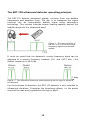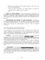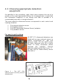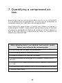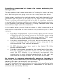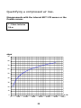
1
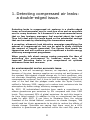
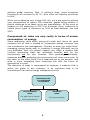
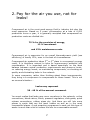
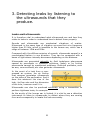
Guide for ultrasonic leak
detection in compressed air
systems in an industrial
environment
Copyright © 2007 by SDT International n.v. s.a.
First edition, English version.
All rights reserved. Reproduction in any form of all or part of this document is
not permitted without the written permission of SDT International n.v. s.a.
SDT International n.v. s.a.
Bd. de l’Humanité 415,
B – 1190 Brussels (BELGIUM)
Tel: ++32.2.332.32.25
Fax: ++32.2.376.27.07
e-mail: [email protected]
web page: http://www.sdt.be
2
Contents
1.
Detecting compressed air leaks: a double-edged
issue. .............................................................................................5
2.
Pay for the air you use, not for leaks!..............................7
3.
Detecting leaks by listening to the ultrasounds that
they produce. .............................................................................9
4.
Implementing a campaign to search for leaks and
drawing the most benefit from it. ...................................11
4.1
4.2
4.3
4.4
4.5
Devising an effective strategy............................................................ 11
Devising the procedure........................................................................ 12
Choosing appropriate detection equipment..................................... 14
Using the SDT 170 detector properly ............................................... 16
Leaks....but where?.............................................................................. 19
5.
Detecting a leak. .....................................................................21
6.
Recording the data.................................................................23
7.
Quantifying a compressed air loss. .................................25
8.
Some practical advice...........................................................37
3
As the indisputable leader in its field, SDT International designs and
produces a large range of measuring instruments for the ultrasonic
detection and evaluation of various other physical parameters.
The company's expertise covers a vast array of applications: large and
small capacity tightness tests and for underground tanks, the detection
of leaks in any pressure system, production quality control and the
detection of wear and faults in the predictive maintenance of
mechanical equipment.
Our company's success is based on our philosophy and our willingness
always to respond to our customers' problems with the most effective,
money-saving solutions.
4
1. Detecting compressed air leaks:
a double-edged issue.
Detecting leaks in compressed air systems is a double-edged
issue: an environmental one for each one of us and an economic
one for every business. Is it because it's an environmental issue
that so few business managers feel worried about the topic?
Then let's deal with this issue based on the substantial savings
that can be made by eliminating this tremendous waste.
A proactive, ultrasonic leak detection campaign
amount of compressed air lost can be used to
the amount of benefit generated. The figures
themselves and will convince you to implement
efficiency management programme.
quantifying the
easily calculate
then speak for
a better energy
When people talk about energy saving prospects the idea of
protecting the environment is, however, never very far
removed. Detecting leaks in your compressed air systems
addresses these two concerns.
An environmental and an economic issue.
Energy is, and will increasingly become, an important, priority issue
because of its price, because supplies are running out and because of
the constant fight against climate change etc. In such conditions, why
not eliminate completely worthless consumption caused by leaks from
compressed air systems? Isn't it time to limit the damage? Especially in
view of the fact that the pledges made under the Kyoto Protocol,
ratified in February 2005, require us to reduce toxic emissions into the
atmosphere by better energy efficiency management.
By 2012, 35 industrialised countries have made a commitment to
reduce greenhouse gas emissions by 5% compared with their 1990
levels. They represent 35% of global emissions. As such this target is
far from being enough. In addition to this no commitment has been
made for after 2012. If you listen to Stephane Dion, the retiring
President of the United Nations' conference on climate changes, "We
would need ten Kyoto agreements to be able to reduce the effects of
climate change. Scientists are saying that there must be a 60%
reduction in greenhouse gas emissions within the next fifty years to
5
stabilise global warming. Well, if nothing's done, these emissions
themselves will increase by 60 %". How much will industry contribute
to this?
While you're watching your energy bills rise, not a day goes by without
new commitments to reduce CO2 emissions' quotas being tackled. A
double challenge to be taken up by any manufacturer. All the more so
because at the beginning of 2007 the European Union undertook to
reduce these types of emissions by 20% at least between now and
2020.
Compressed air leaks are very costly in terms of excess
consumption of energy.
Some awareness, skills within everyone's reach and, above all, good
reactions are all that is needed to incorporate energy concerns into
one's production tool management. Contrary to what you might think,
managing energy better and/ or investing in energy efficiency can be
very profitable. And, this doesn't happen very often, a solution that
involves eliminating leaks has immediate benefits both for the
environment and for your finances. More generally, admittedly,
measures aimed at protecting the environment will incur some costs. In
this case, on the other hand, this is balanced out by the benefits. And
what is more motivating than combining this with the future of
generations to come!
The detection of leaks in compressed air systems, a measure that is
within the grasp of any company, is an important step in its
commitment to an active energy management policy.
Detecting leaks
in compressed
air systems
Environmental
issue.
Economic
issue.
For each one of us and
For every business.
future generations.
6
2. Pay for the air you use, not for
leaks!
Compressed air is the most used energy fluid in industry but also the
most expensive. Based on 5 years' consumption at a rate of 6,000
production hours a year, it is generally accepted that compressed air
production costs are divided into
75 % for the provision of energy,
13 % investment
and 12% maintenance costs.
Compressed air is expensive for an overall thermodynamic yield (use
efficiency) of hardly 10%, even in the best of circumstances.
Compressed air production takes 2nd or 3rd place in a company's energy
costs. It is therefore natural to take its improvement potential into
consideration. It is important and is based essentially on the ideal
balance between actual production requirements and pressure levels,
on reducing energy losses, on maintaining components, on checking air
quality and eliminating leaks in the network.
In some companies, rather than thinking about these improvements,
they bring in a compressor to compensate for these losses. This is not
an unusual situation...
Leaks may represent
30 - 40 % of the amount consumed.
You must realise that leaks may occur anywhere in the network; online
connections, bleed valves, filters, pressure regulators, slide gates, quick
release connections, rubber pipes etc. And there are still lots more
places in spots that are the most hidden as well as in the most
inaccessible places. A real proactive programme to seek out this type of
waste is more than vital to reduce the loss to a reasonable amount:
7
Reducing compressed air losses
to 5 % of the amount consumed.
It's all the more true that if losses prevent minimum service pressure
being reached, you very often tend to increase pressure. Which
increases the percentage of losses. Taking into account the number of
components in any compressed air system, it is easy to imagine the
potential for leaks and the financial benefits of a detection campaign.
This can be calculated very quickly using the cost of the smallest leaks
and by simple multiplication:
A single 1 mm leak at 6 bars
is already costing you €144 per year.
At 12 bars,
it will cost you €480 per year.
Annual costs of energy caused by an undetected leak*.
Hole Ø
[mm]
Loss
Loss of air
Loss
of air at
at
of energy
6 bars
12 bars
in kWh
[l/s]
[l/s]
at 6 bars
Loss
of energy
in kWh
at 12 bars
Costs at
6 bars
[EUR]
Costs at
12 bars
[EUR]
1
1.2
1.8
0.3
1
144
480
1.5
2.6
3.7
0.7
2.0
312
987
2
4.8
7.4
1.2
4.1
576
1.973
2,5
7.5
12.8
1.9
7.5
900
3.413
3
11.1
20.8
3.1
12.7
1,488
6,096
Costs to be multiplied by the number of leaks
*kWh x 0.06 EUR x 8,000 operating hours per year.
8
3. Detecting leaks by listening to
the ultrasounds that they
produce.
Leaks emit ultrasounds.
It is therefore vital to understand what ultrasounds are and how they
relate to leaks in order to understand how to detect them properly.
Sounds and ultrasounds are mechanical vibrations of matter.
Ultrasound is the same type of vibration as sound but at a frequency
higher than 20 kHz, which is inaudible to the human ear, which has a
range of between 15Hz and 20Hz.
Compared with the diffuse emission of sounds, ultrasounds spread in a
concentrated fashion in one direction. They can be compared with a
beam of light whose intensity decreases depending on the distance.
Ultrasounds are generated naturally by fluid turbulence phenomena
caused by pneumatic or hydraulic problems (leaks) or by friction
phenomena caused by mechanical problems. Electrical problems, such
as arcs, corona effects, etc. also generate ultrasounds.
In the event of a leak from a compressed air system, the air friction
that escapes generates ultrasounds
on the sides of the perforation. And it
does this whatever the size of the
leak, its flow rate and the dimension
of the hole, however small it is.
Ultrasounds can also be produced artificially using a transmitter to
perform tightness tests, for example.
As the acuity of the human ear is limited, it is vital to use a detection
instrument to listen to ultrasounds, to detect where they are coming
from and consequently to locate the leak accurately.
9
The SDT 170 ultrasound detector operating principle.
The SDT 170 detects ultrasound signals, converts them into audible
frequencies and amplifies them. The aim is to transpose the signal
received into an interpretable audible signal using heterodyne
technology. This solution extends human hearing capacity beyond the
audible range into the ultrasound band.
Figure 1 - The main function of
the SDT 170 is to convert high
frequency signals into audible
signals.
It must be noted that the detector's central frequency band can be
adjusted to a specific frequency between 15.1 and 190.7 kHz ; the
default frequency is 38.4 kHz.
Figure 2 - The frequency bands are used depending on the type of sound to
be detected.
For the purposes of detection, the SDT 170 detector is only sensitive to
ultrasound vibrations. It restores the turbulence effects, i.e. the actual
sound of the leak and it quantifies this leak in dBµV.
10
4. Implementing a campaign to
search for leaks and drawing the
most benefit from it.
A proactive campaign for looking for leaks requires devising a schedule
for performing services repeatedly over time.
This is completely different from the prompt, unforeseen reactions
required by leaks that appear suddenly. This proactive campaign
involves using the most appropriate tool and attachments for each
location, observing an appropriate methodology, managing the data
relating to each leak, documented, validated repair measures and,
finally, as far as possible, quantifying leaks and doing the calculation
resulting from the campaign.
4.1 Devising an effective strategy
The proper management and success of a maintenance programme for
your compressed air network is based essentially on the quality of your
strategic plan.
•
DEFINE THE OBJECTIVES - Defining what the objectives are
apart from the main one which is to drastically reduce energy costs by
only agreeing to a small investment in a detector is vital.
Any effective maintenance strategy is necessarily based on a well
defined goal. Thus the first question to ask yourself is, quite logically,
"What objectives must be achieved by applying a maintenance plan to
my compressed air network?"
Here are some examples:
-
Drastically reduce your energy costs with just a small investment.
-
Detect, quantify the amount and repair any compressed air leak in
the existing system.
-
Restrict the overall amount of losses to 5% of the amount
consumed.
-
Take the strain off your compressors and prolong their lifespan.
11
-
Make all the staff in your company aware of the high cost
price of compressed air.
-
Train the users involved in the most effective methods for
maintaining the compressed air network.
Etc.
-
•
MAKE ALL STAFF AWARE - To achieve maximum efficiency it is
important to make all staff aware of this by posting permanent notices
about the objectives. These objectives must be spread around the
whole company so that each member of staff comes up against them all
the time.
•
RECONSIDER THE WHOLE OF YOUR NETWORK - Managing a
maintenance programme for your network is much more than looking
for leaks and making repairs. It's also thinking about the network as a
whole and making the improvements that are vital for greater
efficiency.
4.2 Devising the procedure
Your procedure must be devised so that it achieves three results: the
safety, reliability and effectiveness of your programme for looking for
leaks. For optimum management of your compressed air network,
some procedural steps deserve special attention:
•
SAFETY – This means compiling a procedural manual. Particular
attention must be paid to this document. It will specify the frequency of
inspections for each control point as well as the most appropriate
sensor and attachments for each of these points.
The checking procedure will be detailed in five phases: detecting,
locating, quantifying, repairing and checking the repair. It will also
describe how each person involved must record that he has observed
the procedure for each phase and also record information about the
leak.
•
FREQUENCY – An effective annual maintenance plan requires 3
- 4 inspections of all the points of the network. Moving parts or those in
a hazardous environment will be checked every month. You will then
ensure that you have detected all new leaks as early as possible after
they appeared and that you have checked the repairs required by
previous inspections.
12
•
KNOWING ALL ABOUT THE NETWORK – for yourself and the
people involved, knowledge of the network, compressors, the various
pressure levels necessary are vital to devising the maintenance plan
and observing it.
•
UPDATING THE CONTROL PLANS – Keeping the installation
diagrams up to date will enable you to devise the most appropriate plan
of all the points to be checked. All leaks will be recorded there
progressively, with their precise location, their frequency, how big they
are, the type of repair carried out and the check on this.
•
CHOICE OF EQUIPMENT – It is important to determine precisely
the most appropriate sensors and attachments that must be used for
each detection point.
•
TRAINING – All users of the ultrasound leak detector will have
received practical and theoretical training from an experienced person
before starting his job.
•
OBSERVING THE 4 STAGES OF THE PROCEDURE – The four
stages of the programme for looking for leaks must be observed;
identify, locate, repair, check again.
•
CHECKING REPAIRS – To be incorporated into the procedure: an
ultrasound check of each leak repaired. On the one hand, the person
who checks is not always the one who repairs, and, on the other hand,
you have to check that another leak hasn't been created accidentally
when working on the network.
•
DATA MANAGEMENT – Quantifying how much is leaking is a
difficult matter. From feedback from major users and its specialist
expertise, SDT provides you with a unique approach to quantification.
Recording such figures with the history of each leak will allow you to
compile an annual table of savings generated by your network
maintenance. They will also encourage the transfer of skills within your
business.
13
4.3 Choosing appropriate detection
equipment
As specified in the procedure, each check point requires the use of a
sensor or the most appropriate fitting. Let us always bear in mind that
the ultrasound frequency is low energy and that is spreads in a
concentrated way and in a single direction.
The most effective ultrasound sensor corresponds to each control and
locating situation:
•
•
•
•
The
The
The
The
internal detector sensor
flexible sensor
EDS (Extended Distance Sensor) adapter
parabolic sensor.
For easy to get to places
All SDT 170 ultrasound detectors are
fitted with an open internal sensor to
detect compressed air, gas and
vacuum leaks. It's the ideal sensor
for daily searches and for a quick
check of easily accessible places
opposite
the
operator.
Several
precision attachments (fig.3 nos. 2 5) may help to locate exactly where
the leak is.
Figure 3 – The SDT 170's
internal sensor and the precision
attachments.
14
For difficult to get to places
This flexible rod with integral
sensor has been designed to
detect leaks in places deemed
to be inaccessible and to get
round the parts to be checked.
In fact, it can be bent, turned
and pointed in any direction.
Two lengths available: 550 and
820 mm.
Figure 4 – The flexible sensor.
Average distance (up to 10 m).
Generally, a large part of the compressed air system is located at
ceiling level. You need to use a ladder or lifter to inspect it. There is an
easier way… The EDS (Extended Distance Sensor) allows you to inspect
it while keeping your feet on the ground. This conical shaped adapter is
fitted with a threaded tip. It is screwed onto the SDT 170's internal
sensor and concentrates the ultrasonic
frequencies.
It enables better
detection at a medium distance and it
improves
the
accuracy
of
the
approach.
Figure 5 - The EDS (Extended Distance
Sensor) adapter.
15
Long distance (up to 25 - 30 m).
If the place to be inspected or
the leak to be located is out of
range of the detector in spite
of using the EDS (fig. 5), you
can use this parabolic sensor.
This is a high precision signal
concentrator which enables
detection
at
very
long
distances.
This
transparent
plexiglas parabola is fitted with
a particularly sensitive sensor.
It has two sights for extremely
accurate location: one is a
"rifle" sight and the other a
powerful laser sight.
Figure 6 – The parabolic sensor and its
laser sight.
4.4 Using the SDT 170* detector properly
1.
If you don't use the SDT 170 detector's internal sensor, connect
the selected sensor to the connection for the external sensor.
Then connect the headphones to the unit's audio output. You
must use these to search for the leak, to locate it and to be
able to quantify it. You will also be protected from surrounding
parasitic noises.
2.
Start the apparatus (fig. 8 page 18).
16
3.
Ensure that the sensor connected is automatically recognised
by the SDT 170 unit. The sensor ID is displayed in the top left
corner of the screen (fig. 7, Type of sensor).
Figure 7 – The LCD display
4.
Check the battery level on the icon in the upper right corner of
the screen (fig. 7).
5.
After the company safety procedures have been performed, you
start detecting leaks as described in Chapter 5.
*All details in the user manual supplied with the unit.
The importance of the digital display.
Your SDT detector
display or a digital
the digital display
economic approach
may be fitted with a screen with a bar graph
display for measuring the leak. More precisely,
is vital for quantifying leaks in view of an
following your strategy for finding leaks.
Apart from the fact that measures can be traced and it is very userfriendly, there are many advantages from saving data and
transferring it to a PC. Some versions have this option.
17
Figure 8 – The basic functions of the SDT 170
18
4.5 Leaks....but where?
Leaks may occur anywhere in your compressed air system! A look at
the top twelve most common leaks:
1.
Connections on the supply line.
2.
Quick coupler
3.
Filters
4.
Pneumatic cylinders.
5.
Regulator/dryer assembly
6.
Pressure regulators
7.
Rubber pipes
8.
Regulator/lubricator assembly
9.
Isolation valves
10. Control valves
11. Automatic drain traps
12. Various pipes
As a rough guide, the table below gives you the distribution of
compressed air used in industry where there is absolutely no proactive
predictive network maintenance programme.
Distribution of the amounts of compressed air used in
industry (international averages)
Consumption by equipment
43 %
Leaks into the atmosphere
34 %
Inappropriate uses
16 %
Purged air
5%
Failed drain traps
2%
These figures are averages drawn up by Plant Support & Evaluations Inc. – Audit
Division
19
20
5. Detecting a leak.
The detection service as such requires the application of some basic
principles aimed mainly at efficiency and ease of work.
•
For repeating and comparing measures you will always use the
same sensor and/or attachment for the same place to be
tested.
•
The unit's level of amplification will be selected depending on
the working environment.
•
The exact location will be determined by sweeping in all
directions searching for the strongest ultrasound signal. This is
when the highest value appears on the screen. It's simple and
intuitive given that it's actually the noise of the leak that you
are hearing.
•
If it is not to be repaired immediately you will have to provide
an exact location of the place.
•
Each repair must be checked as must the immediate surroundings.
Procedure:
1.
Start searching with maximum amplification, sweeping from the top
to the bottom and from left to right with the unit or the sensor that
you have connected to the unit, in order to locate the leak
accurately.
Detecting the hissing sound that is typical of ultrasounds indicates
that there is a compressed air or vacuum leak. If the signal
detected is too powerful, reduce the amplification level to make it
more comfortable to work.
2.
As soon as you detect the hissing sound, move the sensor closer to
the source to locate the leak. Press the down arrow to reduce the
signal level given that it will increase as you approach the precise
location of the leak.
21
3.
This will be at the place where the signal is most powerful and
when the highest value is displayed on the screen.
4.
Select the amplification level depending on your working
environment so that you do not have either of the two indicator
arrows on the screen of the SDT 170. They may, still be there when
the amplification level is at its maximum (A=80) or at its minimum
(A=10).
5.
Note down or save the leak measurement (dBµV) displayed on the
screen.
6.
Report this precise spot if the leak is to be repaired immediately or
mark it with a locating mark if it is to be repaired later.
7.
Note down as much information as possible about the leak: the
place, the type of leak, how big it is, the identity of the inspector
and the repairer are very useful items to note down.
Compressed air is expensive.
Compressed air losses = waste!
1. Controlling this energy vector is an absolute necessity.
Compressed air is expensive.
2. Compressed air costs €0.6 - 3.0 per Nm³ depending on the
optimisation of the plant.
3. The overall thermodynamic efficiency (efficiency of use) of a plant
is very low: only ± 10 % on average taking into account energy
leakage, motor, transmission and compressor losses, load losses and
leaks.
The potential for improvement is therefore very great.
22
6. Recording the data.
Recording data relating to each leak inspected is a vital step in your
campaign to search out leaks. It must be incorporated into your
maintenance plan with the option to add records appropriate for your
strategy which will meet the objectives of each campaign.
Example of an internal data record sheet for an inspected leak.
COMPANY LOGO
Detecting compressed
air leaks:
DEPARTMENT: ................................................
MACHINE (or premises): ..................................
INSPECTOR: …………………………………….
SENSOR: …………………………………………
MEASURING DISTANCE: ………………………
Date
and
inspector
Department
Leak
number
Description
and
location
Size of
the leak
in dBµV
23
Loss
of air
in
L/h
Air
loss
€/y
/y
Person
responsible
and date of
repair
Person
responsible
and date of
second
check
Data recorded for the inspected leak:
Date and inspector
Date and name of the person responsible for checking leaks.
Department
Part of the plant in which the inspection took place (e.g. production
workshop, packaging unit etc.).
Leak number
Number on the leak locating mark.
Description/location
Description and location of the leak (e.g. on the left side of the T at the
outlet of boiler no. XXX or at the inlet to pump no. YYYY, see diagram
Z).
Size of the leak in dBµV
The value measured and displayed on the detector screen.
Air loss in L/hour
See tables from page 28 "Quantifying a compressed air loss".
Air loss in €/year
If you have the cost prices of compressed air in your company you can
easily estimate the annual financial loss resulting from this leak.
Person responsible and date of repair
Actual date the repair was finished and the name of the person who
carried it out.
Person responsible and date of re-check
Date the repaired leak underwent a second ultrasound check and the
name of the inspector.
24
7. Quantifying a compressed air
loss.
Quantifying a leak by converting the dBµV into L/y or into SCCM/SCFM
is to be planned with the greatest care. It should only be undertaken by
competent people who have been trained appropriately.
Given that a very large number of factors may influence the taking of
measurements in dBµV, it goes without saying that the user of this type
of measuring equipment will first of all include all of these factors so
that he can take account of them when he makes his conclusions on
quantifying a detected leak.
When detecting leaks in an industrial environment, certain
factors may influence the measurements:
The leak orifice size, its shape, its configuration.
The surrounding parasitic ultrasound signals.
The distance between the leak and the sensor.
The position and the working angle of the sensor in relation to the
leak axis.
The features of the ultrasound sensor and the conditions under which
it is used.
The temperature and humidity level of the air escaping from the leak.
… and very many more.
25
Quantifying compressed air losses also means evaluating the
savings made.
The big question that's asked most often is "Looking for leaks is all very
well. But what good is it going to do me? Is it really worth the effort?"
Under certain conditions the method enables each leak detected to be
quantified and the gains to be had from its repair to be calculated.
There is nothing more gratifying that to be able to compile a quarterly
or annual table of savings made by your network maintenance services,
in the certainty that energy efficiency is being managed better and
there will be a rapid return on investment.
In the tables below you will find the values in dBµV measured for a
determined compressed air leak whatever the pressure up to 10 bars
inclusive.
•
The dBµV measurements in the first two tables are the results
of detecting with the internal sensor or the flexible sensor using
an SDT 170 S+, M, M+ or MD unit, given that the 170 S model
does not have a digital display of the measured value.
•
The dBµV measurements in the third and fourth tables are the
results of detecting with the parabolic sensor, using one of the
units mentioned in the previous paragraph.
•
All SDT detectors have been used in the default 38.4 kHz
central frequency band.
•
The dBµV values were recorded at the loudest level of the leak.
They are, therefore, maximum values. You will note that when
using the SDT detector in an industrial environment, this
noisiest level is rarely detected perpendicular to the leak, but
most often at an angle of about 30° to the axis of the leak.
An increase in pressure automatically causes an increase in
flow. And, at the same time, the ultrasound signals measured in
dBµV by the SDT 170 detector also increase.
You can, therefore, favourably deduce from this that quantifying leaks
based on the SDT 170 measurements is independent of the level of
pressure used (not always known).
26
Details of the leak used:
Leak orifice: from 0.2 - 1 mm
Area: from 0.033 - 0.822 mm²
Important note:
The values in these tables are given as a rough guide and may only be
used as guidelines to make the task easier.
27
Quantifying a compressed air loss.
Measurements with the internal SDT 170 sensor or the
flexible sensor.
1 - 6 bars inclusive
0.4 m
dBµV
90
80
70
60
50
40
30
20
10
L/h
0
0
500
1000
1500
2000
28
2500
3000
3500
dBµV
L/h
SCCM
SCFM
20
141
2355
0.083
22
158
2627
0.093
24
176
2931
0.104
26
196
3270
0.115
28
219
3647
0.129
30
244
4069
0.144
32
272
4539
0.160
34
304
5063
0.179
36
339
5648
0.199
38
378
6301
0.223
40
422
7029
0.248
42
470
7841
0.277
44
525
8747
0.309
46
585
9758
0.345
48
653
10885
0.384
50
729
12143
0.429
52
813
13546
0.478
54
907
15111
0.534
56
1011
16858
0.595
58
1128
18805
0.664
60
1259
20978
0.741
62
1404
23402
0.826
64
1566
26106
0.922
66
1747
29123
1.028
68
1949
32488
1.147
70
2174
36241
1.280
72
2426
40429
1.428
74
2706
45100
1.593
76
3019
50311
1.777
29
Quantifying a compressed air loss.
Measurements with the internal SDT 170 sensor or the
flexible sensor.
1 - 10 bars inclusive
2m
dBµV
90
80
70
60
50
40
30
20
10
0
0
1000
2000
3000
4000
30
5000
L/h
6000
dBµV
L/h
SCCM
SCFM
10
225
3745
0.132
12
250
4169
0.147
14
278
4641
0.164
16
310
5167
0.182
18
345
5753
0.203
20
384
6404
0.226
22
428
7130
0.252
24
476
7938
0.280
26
530
8837
0.312
28
590
9838
0.347
30
657
10953
0.387
32
732
12194
0.431
34
815
13575
0.479
36
907
15113
0.534
38
1010
16826
0.594
40
1124
18732
0.662
42
1251
20854
0.736
44
1393
23217
0.820
46
1551
25847
0.913
48
1727
28776
1.016
50
1922
32036
1.131
52
2140
35665
1.260
54
2382
39706
1.402
56
2652
44205
1.561
58
2953
49213
1.738
60
3287
54789
1.935
62
3660
60996
2.154
64
4074
67907
2.398
66
4536
75600
2.670
68
5050
84165
2.972
70
5622
93701
3.309
31
Quantifying a compressed air loss.
Measurements with the SDT 170 and the parabolic
sensor.
5 - 10 bars inclusive
2m
dBµV
90
80
70
60
50
40
L/h
30
0
1000
2000
3000
32
4000
5000
6000
dBµV
L/h
SCCM
SCFM
65
756
12600
0.445
66
855
14250
0.503
67
956
15933
0.563
68
1059
17650
0.623
69
1165
19417
0.686
70
1274
21233
0.750
71
1385
23083
0.815
72
1500
25000
0.883
73
1618
26967
0.952
74
1740
29000
1.024
75
1866
31100
1.098
76
1996
33267
1.175
77
2132
35533
1.255
78
2274
37900
1.338
79
2422
40367
1.426
80
2580
43000
1.519
81
2744
45733
1.615
82
2920
48667
1.719
83
3110
51833
1.831
84
3318
55300
1.953
85
3548
59133
2.088
86
3810
63500
2.243
87
4125
68750
2.428
88
4550
75833
2.678
33
Quantifying a compressed air loss.
Measurements with the SDT 170 and the parabolic
sensor.
5 - 10 bars inclusive
5m
dBµV
90
80
70
60
50
40
30
L/h
20
0
2000
4000
34
6000
8000
dBµV
L/h
SCCM
SCFM
56
944
15733
0.556
57
1052
17533
0.619
58
1164
19400
0.685
59
1280
21333
0.753
60
1400
23333
0.824
61
1516
25267
0.892
62
1632
27200
0.961
63
1770
29500
1.042
64
1902
31700
1.120
65
2040
34000
1.201
66
2186
36433
1.287
67
2333
38883
1.373
68
2490
41500
1466
69
2656
44267
1.563
70
2830
47167
1.666
71
3016
50267
1.775
72
3217
53617
1.894
73
3438
57300
2.024
74
3682
61367
2.167
75
3964
66067
2.333
76
4305
71750
2.534
77
4776
79600
2.811
35
Table correlating the diameter of the leak, its volume and the
loss of energy.
Diameter of the
leak
Volume of air lost
at 6.2 bars
Power required
mm
inch
L/h
SCCM
SCFM
kW
1.6
1/16
3 570
59 466
2.1
0,3
3.2
1/8
36 040
600 320
21.2
3,1
6.4
1/4
97 240
1 619 732
57.2
8,3
9.5
3/8
222.5
33
378 250 6 300 533
Information source for this table: Atlas Copco Compressed Air.
Annual cost in electricity for the compressor power supply.
Pk
kWh
Cost (EUR)
Cost (USD)
5
3.7
1 196
1 415
10
7.4
2 391
2 830
20
14.7
4 712
5 576
30
22.1
7 102
8 405
60
44.2
14 134
16 727
100
73.6
23 628
27 962
150
110.4
35 442
41 943
300
220.8
70 814
83 803
500
368.0
117 998
139 643
700
515.2
165 254
195 567
1000
736.0
236 068
279 370
Base 24h/24h=8,760 h/year
Price:€0.037/kWh
36
8. Some practical advice.
1. Use simple screen effect techniques in order to eliminate any
parasitic noise.
Ultrasounds are directional, in other words, they spread in one direction
only. Use your body or a piece of cardboard to make a screen between
the parasitic ultrasound (from the bleed valve for example) and the
place where you are trying to detect the leak. Put a rag or your hand
above the sensor in order to indicate the exact location of the leak.
2. Be careful of reflection phenomena.
When looking for a leak it seems sometimes that the leak is coming
from a wall, a partition, the ground or a place where it is obvious that
no ultrasound is being created. We are then faced with the laws of
reflection. Ultrasounds are partially absorbed by the material on which
they are reflected and partially reflected by this material. When faced
with a reflection phenomenon, you must estimate the angle of
reflection and place yourself in the direction of the angle of incidence
(the direction the leak is coming from). In relation to the reflection
surface the two angles are equal. When looking for the leak in the
direction of incidence the height where it is detected in the headphones
should be higher than the height detected in the direction of reflection.
3. Absorption of ultrasound.
As we have already described in the trick above, part of the ultrasound
signal is absorbed by the object on which the ultrasounds are reflected.
This absorption factor depends entirely on the material of the object on
which the ultrasound signals are reflected. A fabric-covered surface
absorbs the sound much more or reflects it much less than a concrete
or metal surface.
37
4. Locating a leak precisely.
It isn't normally enough to stop detecting a leak a few centimetres
away from the assumed leak. In order to locate the leak precisely you
must always check the area surrounding it because the precise location
of the leak may be in the same direction as the one you were looking
for. All the more so if a compressed air system is behind a pipe or a
flange. This is why it is advisable to carry out an inspection of the area
all around the suspected leak.
5. Quantifying leaks.
To quantify leaks as accurately as possible you must always start from
the maximum dBµV value.
This is equivalent to the highest leak sound detected.
Only the highest value can be considered, recorded in the internal
memory and then transferred to the computer. By inserting these
values in the appropriate Excel lists, it becomes easy to calculate the
total air loss (loss in €).
38
39
Detecting leaks in compressed air systems is a double-edged issue: an
environmental one for each one of us and an economic one for every
business. Is it because it's an environmental issue that so few business
managers feel worried about the topic? Then let's deal with this issue
based on the substantial savings that can be made by eliminating this
tremendous waste.
A proactive, ultrasonic leak detection campaign quantifying the amount
of compressed air lost can be used to calculate the amount of savings
made. The figures then speak for themselves and will convince you to
implement a better energy efficiency management programme.
Eliminating compressed air leaks has immediate benefits both for the
environment and for your finances. More generally, admittedly,
measures aimed at protecting the environment will incur some costs. In
this case, on the other hand, this is balanced out by the benefits. And
what is more motivating than combining this with the future of
generations to come!
The detection of leaks in compressed air systems, a measure that is
within the grasp of any company, is an important step in its
commitment to an active energy management policy.
The solution is there. It is simple and
easy to implement. It enables you to
make substantial savings and goes well
beyond eliminating a great waste of
energy.
And however, compressed air is still
often forgotten when programmes for
reducing production costs are drawn up.
André DEGRAEVE, Manager SDT International
SDT International s.a.
Bd. de l’Humanité 415,
B – 1190 Brussels (BELGIUM)
Tel: ++32.2.332.32.25
Fax: ++32.2.376.27.07
e-mail: [email protected]
web page: http://www.sdt.be