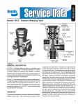
1
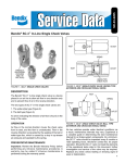
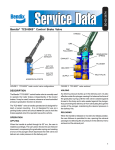
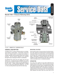
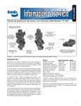
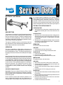
SD-06-130
®
Air Horns and Valves
for air brake system components. At a minimum, the air
horns and valves should be inspected every 6 months or
1500 operating hours, whichever comes first, for proper
operation. Should the air horns and valves not meet the
elements of the operational tests noted in this document,
further investigation and service of the valve may be required.
TESTING FOR SERVICEABILITY
DESCRIPTION
The purpose of our air horn is to provide a warning signal of
greater volume and farther carrying qualities than usually
found on automotive vehicles. The horn is designed on the
principle of a vibrating diaphragm. The horn consists of die
cast bodies, diaphragms, and two chrome plated horn bells,
with the bells in a horizontal position.
Two types of operating valves are commonly used, the
foot-operated horn valve and the hand-operated horn valve.
Each of these valves have a built-in strainer.
OPERATING TEST
1. With air pressure in the system, operate the horn valve
and the horn should give a loud, clear dual tone horn
blast.
LEAKAGE TEST
1. With horn valve in the released position, leakage at the
delivery port or at the valve stem at the top of the horn
valve should not exceed a 1” soap bubble in 5 seconds
(100 SCCM).
2. With the horn valve applied, leakage at the stem at the
top of the horn valve should not exceed a 1” soap bubble
in 5 seconds (100 SCCM).
REMOVING
To remove the air horn or horn valve;
OPERATION
The horn is operated by pulling down on the lever of a
hand-operated horn valve or pushing down on the button of
the foot-operated horn valve. This action pushes down on
the supply valve stem in the horn valve and opens the supply
valve.
When the supply valve in the horn valve is opened, air passes
through the horn valve and enters the cavity in the air horn
on one side of the diaphragms. As the air pressure builds up
on the diaphragm, it deflects it and the air escapes through
the horn bells. This action sets up a vibration of the diaphragm
in each horn bell. The two different lengths of horn bells give
the horn its dual tone. The vibrations are set up in an air
column denser than atmosphere, due to escaping
compressed air, which provides unusual tone carrying
qualities.
PREVENTIVE MAINTENANCE
Important: Review the Bendix Warranty Policy before
performing any intrusive maintenance procedures. A warranty
may be voided if intrusive maintenance is performed during
the warranty period.
No two vehicles operate under identical conditions; as a
result, maintenance intervals may vary. Experience is a
valuable guide in determining the best maintenance interval
AIR HORN
1. Disconnect the air line to the air horn.
2. Remove air horn mounting nut and remove horn.
HORN VALVE
1. Drain air brake system.
2. Disconnect air lines to the horn valve.
3. Remove mounting bolts and remove horn valve.
INSTALLING
To install an air horn or air horn valve;
AIR HORN
1. Mount horn on top side of vehicle roof or under hood.
2. Securely bolt horn on a flat surface and use care to be
sure the body is not distorted.
3. The horn bells should point down slightly for adequate
draining.
4. Install at least 1/4" O.D. tubing to the air horn.
HORN VALVE
1. Mount the valve in the cab where it can be easily removed
for servicing.
2. Mount so that pull-cord for the hand-operated valve will
be within easy reach of driver.
3. Mount the foot-operated valve on floor in a convenient
location for driver’s left foot.
4. Connect air lines to the horn valve.
1
DISASSEMBLY
TEST OF REBUILT AIR HORN AND HORN VALVE
AIR HORN
1. Remove the eight nuts and bolts holding the two covers
to the body.
2. Remove the diaphragms from the body of the air horn.
3. Remove the spring contact, springs, and spring
assemblies from the covers of air horn.
4. Remove the horn bells from the body.
Both operating test and leakage test must be made after
rebuilding or repairing an air horn or horn valve. If the air horn
does not operate satisfactorily, adjustment of the spring load
behind the diaphragm can be made by turning the adjusting
screw in the cover. Before attempting to turn the adjusting
screw, loosen the adjusting screw lock nut. Be sure to tighten
the adjusting screw lock nut after any adjustment.
HORN VALVE
1. Remove the spring cage from the valve body.
2. Remove the valve stem from the valve body.
3. Remove the strainer and spring from the spring cage.
WARNING! PLEASE READ AND FOLLOW
THESE INSTRUCTIONS TO AVOID
PERSONAL INJURY OR DEATH:
CLEANING AND INSPECTION
AIR HORN
1. Wash all metal parts in cleaning solvent.
2. Carefully inspect the diaphragms to be sure they are not
cracked, deteriorated, or distorted in any way. If ridges
or cracks are found, the diaphragms must be replaced.
3. Inspect condition of the body. Be sure diaphragm seat
in body is not chipped or damaged in any way. Check
for cracks in the body. If these conditions prevail, replace
body.
4. Inspect condition of the covers. Be sure diaphragm seat
in cover is not chipped or damaged. Inspect the cover
for cracks. If these conditions prevail, replace covers.
5. Inspect the horn bells. If they are cracked or broken,
they should be replaced.
6. Inspect the spring contacts. If distorted or deteriorated,
they should be replaced.
7. Check the spring. If broken, replace.
HORN VALVE
1. Inspect supply valve and seat. If damaged, they should
be repaired or replaced.
2. Check the spring. If broken, replace.
3. Be sure the valve stem does not bind when inserted in
the valve body.
ASSEMBLY
NOTE: When using pipe thread sealant during assembly
and installation, take particular care to prevent the
sealant from entering the valve itself. Apply the
sealant beginning with the second thread back from
the end.
AIR HORN
1. Place the diaphragms in the body.
2. Install the spring contacts, springs, and spring
assemblies to the covers.
3. Install the eight bolts and nuts, attaching cover to the
body. Care should be used to be sure equal pressure is
exerted on all the screws holding the cover to the body.
4. Assemble the horn bells to the body.
HORN VALVE
1. Insert the valve stem in the valve body.
2. Place the strainer and spring in the spring cage.
3. Assemble the spring cage to the body.
2
When working on or around a vehicle, the following
general precautions should be observed at all times.
1. Park the vehicle on a level surface, apply the
parking brakes, and always block the wheels.
Always wear safety glasses.
2. Stop the engine and remove ignition key when
working under or around the vehicle. When
working in the engine compartment, the engine
should be shut off and the ignition key should be
removed. Where circumstances require that the
engine be in operation, EXTREME CAUTION should
be used to prevent personal injury resulting from
contact with moving, rotating, leaking, heated or
electrically charged components.
3. Do not attempt to install, remove, disassemble or
assemble a component until you have read and
thoroughly understand the recommended
procedures. Use only the proper tools and observe
all precautions pertaining to use of those tools.
4. If the work is being performed on the vehicle’s air
brake system, or any auxiliary pressurized air
systems, make certain to drain the air pressure from
all reservoirs before beginning ANY work on the
vehicle. If the vehicle is equipped with an AD-IS™
air dryer system or a dryer reservoir module, be
sure to drain the purge reservoir.
5. Following
the
vehicle
manufacturer’s
recommended procedures, deactivate the electrical
system in a manner that safely removes all
electrical power from the vehicle.
6. Never exceed manufacturer’s recommended
pressures.
7. Never connect or disconnect a hose or line
containing pressure; it may whip. Never remove a
component or plug unless you are certain all
system pressure has been depleted.
8. Use only genuine Bendix ® replacement parts,
components and kits. Replacement hardware,
tubing, hose, fittings, etc. must be of equivalent
size, type and strength as original equipment and
be designed specifically for such applications and
systems.
9. Components with stripped threads or damaged
parts should be replaced rather than repaired. Do
not attempt repairs requiring machining or welding
unless specifically stated and approved by the
vehicle and component manufacturer.
10. Prior to returning the vehicle to service, make
certain all components and systems are restored
to their proper operating condition.
BW1592 © 2004 Bendix Commercial Vehicle Systems LLC All rights reserved. 4/2004 Printed in U.S.A.