1
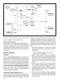
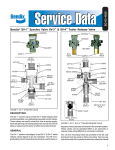
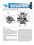
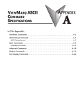
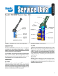
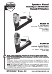
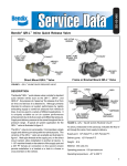
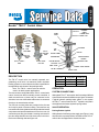
SD-03-3625
Bendix® TW-12™ Control Valve
CONTROL
CABLE
CONNECTION
LEVER CAM
LEVER
PIVOT
LEVER
CAM
LEVER CAM
PIVOT
LEVER
YOKE
CAM
FOLLOWER
MOUNTING
HOLE (2)
1/8" P.T.
RETURN
PORT
1/4" P.T. SUPPLY
PORT
LEVER
YOKE
PLUNGER
CAP
NUT
1/4" P.T.
DELIVERY
PORT
PISTON
PISTON O-RING
PISTON RETURN
SPRING
RETURN PORT
SUPPLY PORT
CAP NUT
PISTON RETURN
PASSAGE
DELIVERY PORT
INLET VALVE
CAP NUT O-RING
INLET VALVE SPRING
SUPPLY PORT
TM
FIGURE 1- TW-12 CONTROL VALVE
DESCRIPTION
The TW-12™ control valve is a manually operated, nongraduating, on-off valve. It is extensively used in hydraulic
braking systems to control devices that are responsible for
the application and release of the parking brakes.
Note: The TW-12™ control valve can also be
used in air brake system applications.
The most common configuration of the TW-12™ control valve
uses a levered cam that is manually, remote controlled. A
dash mounted lever or button may be connected to the
aluminum lever cam via Bowden cable control or connected
directly to the transmission selector.
Two .28 inch mounting holes are provided in the die cast
zinc body for panel or frame mounting. Two steel hex cap
nuts at the ends of the cylindrical valve body retain the internal
components and provide attachment for the lever cam. All
connection ports are pipe threads. Lettering embossed in
the valve body identifies two of the three ports in the valve.
Refer to the following chart and figure one.
Connection
Body Ident. Thread Sizex
Supply
SUP
1/4" P.T. xx
Delivery
DEL
1/4" P.T. xx
Vent
NONE
1/8" P.T. xx
OPERATION
SYSTEM CONNECTIONS
Although the TW-12™ valve can be used in a variety of different
systems and connected in different ways, figure 2 illustrates
a typical hydraulic parking brake system. In this system
the TW-12™ valve controls an HR-1™ hydraulic relay that in
turn applies and releases hydraulic spring brakes.
VALVE OPERATION
Parking Brakes Applied
With hydraulic fluid flowing to the supply port (Figure 1) and
the piston in the upward position, fluid flow into the TW-12™
control valve is stopped at the closed inlet valve.
1
IN
POWER
STEERING
GEAR
OUT
OUT
IN
RETURN
HYDRAULIC
BRAKE
BOOSTER
MASTER
CYLINDER
TW-12™
CONTROL
VALVE
IN
HYDRAULIC
SPRING BRAKE
ACTUATOR
TO SERVICE
BRAKES
DELIVERY
SUPPLY
SUPPLY
CONTROL
DELIVERY
RETURN
HYDRAULIC
RESERVOIR
RETURN
DELIVERY
HR-1™
HYDRAULIC
RELAY
HYDRAULIC
SPRING BRAKE
ACTUATOR
RETURN
POWER
STEERING
PUMP
IN
OUT
FIGURE 2 - TW-12™ CONTROL VALVE HYDRAULIC PARK SYSTEM
The TW-12™ valve delivery port is open to its return port
through a passage in the center of the piston.
Parking Brakes Released
When the TW-12™ control valve plunger is depressed by the
cam action of the lever (Figure 1) the piston contacts the
inlet valve, closing the return passage. Continued piston
movement pushes the inlet valve off its seat in the body,
allowing hydraulic fluid to flow through the valve and out the
delivery port.
SERVICE CHECKS
GENERAL
Read the "General Safety Guidelines" presented in this
manual before beginning any testing or service procedure.
With the TW-12™ control valve installed in the vehicle brake
system, proper valve operation can only be observed by the
reaction of the system and components controlled by the
TW-12™ valve. If malfunction or internal leakage is suspected
or specific operational and leakage testing is desired, the
TW-12™ valve must be removed and bench tested. Bench
testing of the TW-12™ valve is accomplished using air
pressure regardless of its application or the braking media
used in the vehicle brake system.
OPERATING AND LEAKAGE TESTS
Function test the TW-12™ valve while it is installed in the
system by starting the engine and warming the vehicle brake
system for 5 minutes. Move the lever cam from one extreme
2
position to the other three times and observe that the
components controlled by the TW-12™ control valve function
promptly to the ON then OFF condition. Inspect the exterior
of the TW-12™ valve. If the TW-12™ valve is used to control
hydraulic brakes, no fluid leakage should be noted. Pay
particular attention to the area around and beneath the lever
cam.
1. When bench testing the TW-12™ control valve, attach a
small reservoir volume to the delivery port with an air
gauge installed.
Note: 6-8 feet of ½” tubing or hose could be
used in lieu of a small reservoir.
2. Apply a 120psi air pressure source to the supply port
and move the lever cam to the applied and released
position three times. Note that delivered air pressure is
the same as supply air pressure in the applied position
and that air is promptly exhausted in the released
position.
3. With the TW-12™ control valve in the released position
and 120psi at the supply port, apply a soap solution to
the return port and around the supply port cap nut.
Leakage should not exceed a 1” bubble in less than 5
seconds (100 SCCM) at the return port. No leakage is
permitted at the cap nut.
4. Place the valve in the applied position and again apply a
soap solution to the return port. Leakage should not
exceed a 1” bubble in less than 5 seconds (100 SCCM)
at the return port.
5. With 120psi applied to the supply and return ports
simultaneously, apply a soap solution around the plunger
and cam follower in the yoke assembly. Leakage should
not exceed a 1” bubble in less than 5 seconds (100
SCCM).
If the TW-12™ valve does not function as described or if
excessive leakage is detected, it is recommended that it be
replaced with a genuine Bendix® service replacement.
PREVENTIVE MAINTENANCE
Important: Review the Bendix Warranty Policy before
performing any intrusive maintenance procedures. A warranty
may be voided if intrusive maintenance is performed during
the warranty period.
No two vehicles operate under identical conditions, as a
result, maintenance intervals may vary. Experience is a
valuable guide in determining the best maintenance interval
for system components. At a minimum the TW-12™ valves
should be inspected every 6 months or 1500 operating hours,
whichever comes first.
1. Check the TW-12™ control valve for proper operation.
2. Inspect the exterior of the valve for signs of leakage and
any apparent physical damage.
3. Inspect the control cable and its connection point to the
lever cam for damage and wear.
If the TW-12™ control valve does not function as required or
if leakage excessive, wear, or damage is noted during
inspection, replace the valve with a genuine Bendix® service
replacement unit.
GENERAL SAFETY GUIDELINES - WARNING!
PLEASE READ AND FOLLOW THESE
INSTRUCTIONS TO AVOID PERSONAL
INJURY OR DEATH:
When working on or around brake systems and components,
the following precautions should be observed at all times:
1. Park the vehicle on a level surface, apply the parking
brakes, and always block the wheels. When working
around or under the vehicle, stop the engine and remove
the key from the ignition. Always keep hands away
from chambers as they may apply as system pressure
drops. Always wear safety glasses.
2. When working in the engine compartment, the engine
should be shut off and the ignition key should be
removed. Where circumstances require that the engine
be in operation, EXTREME CAUTION should be used
to prevent personal injury resulting from contact with
moving, rotating, leaking, heated or electrically charged
components.
3. Do not attempt to install, remove, disassemble or
assemble a component until you have read and
thoroughly understand the recommended procedures.
Use only the proper tools and observe all precautions
pertaining to the use of those tools.
4. Following the vehicle manufacturer’s recommended
procedures, deactivate the electrical system in a manner
that safely removes all electrical power from the vehicle.
5. If the vehicle is equipped with an air over hydraulic brake
system or any auxiliary pressurized air system, make
certain to drain the air pressure from all reservoirs before
beginning ANY work on the vehicle. If the vehicle is
equipped with an AD-IS® air dryer system or a dryer
reservoir module, be sure to drain the purge reservoir.
6. Never connect or disconnect a hose or line containing
pressure; it may whip. Never remove a component or
pipe plug unless you are certain all system pressure
has been depleted.
7. Never exceed manufacturer’s recommended pressure.
8. Never attempt to disassemble a component until you
have read and understand all recommended procedures.
Some components contain powerful springs and injury
can result if not properly disassembled. Use only proper
tools and observe all precautions pertaining to use of
those tools.
9. Use only genuine Bendix ® replacement parts,
components and kits.
A. Use only components, devices and mounting and
attaching hardware specifically designed for use
in hydraulic brake systems.
B. All replacement hardware, tubing, hose, fittings, etc.
must be of equivalent size, type and strength as
the original equipment.
10. Components with stripped threads or damaged parts
should be replaced rather than repaired. Do not attempt
repairs requiring machining or welding unless specifically
stated and approved by the vehicle and component
manufacturer.
11. Prior to returning the vehicle to service, make certain all
components and systems are restored to their proper
operating condition.
VALVE REMOVAL
1. Park the vehicle on a level surface and block the wheels
and/or hold the vehicle by means other than the service
brakes.
2. Remove pressure from the vehicle service and parking
brake system. In the case of a hydraulic brake system
consult the vehicle manual for proper procedures to be
followed.
3. Identify and mark or label all lines and their respective
connections on the valve to facilitate ease of installation.
3
4. Disconnect all lines and the control cable from the lever
cam.
5. Remove the valve from the vehicle.
VALVE INSTALLATION
1. Install all line fittings and plugs making certain thread
sealing material, if used, does not enter the valve.
2. Install the valve on the vehicle.
3. Reconnect all lines to the valve using the identification
made during VALVE REMOVAL (step 3). Reconnect the
control cable to the lever cam.
4. After installing the valve, test all fittings for excessive
leakage and tighten as needed.
5. Perform operational and leakage inspections prior to
returning the vehicle to service. In the case of a hydraulic
brake system consult the vehicle manual for proper
procedures to be followed.
4
BW2578 © 2006 Bendix Commercial Vehicle Systems LLC.
6/2006 Printed in U.S.A. All rights reserved.