1
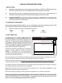
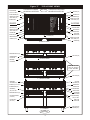
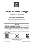
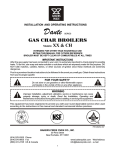
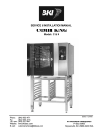
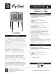
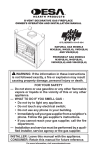
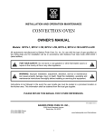
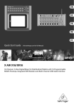
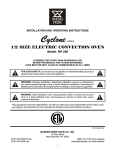
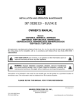
INSTALLATION AND OPERATING INSTRUCTIONS
Dante
SERIES
GAS CHAR BROILERS
Models: F, C and L
INTENDED FOR OTHER THAN HOUSEHOLD USE
RETAIN THIS MANUAL FOR FUTURE REFERENCE
BROILER MUST BE KEPT CLEAR OF COMBUSTIBLES AT ALL TIMES
IMPORTANT INSTRUCTIONS
After the gas supply has been connected to your unit, it is extremely important to check piping for possible
leaks. To do this, use soap and water solution or solutions which are expressly made for this purpose. DO
NOT USE matches, candles, flames, or other sources of ignition since these methods are extremely
dangerous.
Post in a prominent location instructions to be followed in the event you smell gas. Obtain these instructions
from your local gas supplier.
FOR YOUR SAFETY: Do not store or use gasoline or other flammable
!
vapors and liquids in the vicinity of this or any other appliance.
!
!
WARNING: Improper installation, adjustment, alteration, service or
maintenance can cause property damage, injury or death. Read the Installation,
Operating and Maintenance Instructions thoroughly before installing or
servicing this equipment.
!
This equipment has been engineered to provide you with year round dependable service when used
according to the instructions in this manual and standard commercial kitchen practices.
BAKERS PRIDE OVEN CO., INC.
P/N U4180A 3/07
30 Pine Street
New Rochelle, NY 10801
+1 (800) 431-2745 US & Canada
+1 (914) 576-0200 Phone
+1 (914) 576-0605 Fax
[email protected] E-Mail
www.bakerspride.com Web Address
1
CONTENTS
SECTION
PARAGRAPH
ITEM
PAGE
I. INSTALLATION INSTRUCTIONS
3
1
2
3
4
5
6
7
8
9
10
11
12
Installation
Clearances
Gas Connection
Burners
Radiant Units
Glo-Stone Units
Grease Drawer & Water Pans
Griddle Plate
Smoker Boxes
Lighting Instructions
Additional Instructions
Installation with Casters
3
3
3
4
4
4
5
5
5
5
6
6
II. OPERATING INSTRUCTIONS
6
1
2
Lighting Instructions
Broiling
6
6
III. MAINTENANCE
7
1
2
Service
Care and Cleaning
7
7
IV. ILLUSTRATIONS
8&9
V. REPLACEMENT PARTS
8
VI SERVICE CENTERS
8
VII. WARRANTY
11
NOTE: Description of Model numbers and Definition of Prefixes used throughout this manual are shown below:
MODEL DEFINITION
F = Floor Model
R = Radiant Type
C = Counter Top Model
GS = Glo-Stone Type
L = Low Profile Model
H = High-Heat
MODEL SIZES
(F, C, L) Width (R, GS)- (H)
Number of Burners
24
5
30
6
36
8
48
11
60
14
72
17
84
20
165
198
210
252
255
306
300
360
BTU/hr (x 1,000) (North America)
Standard
High-Heat
75
90
2
90
108
120
144
I. INSTALLATION INSTRUCTIONS
1. INSTALLATION:
(i)
Installation of this broiler must conform with the latest edition of ANSI Z223.1/NFPA National Fuel
Gas Code in USA ( CSA-B-149.1 or 2 Installation Code in Canada) and/or local codes.
(ii)
Use this Broiler only with an adequately sized exhaust hood. The room in which this broiler is
installed must be suitably vented in accordance with the National and or local codes.
(iii)
In MASSACHUSETTS: All gas products must be installed by a “Massachusetts” licensed plumber
or gas fitter. Ventilation hoods must be installed in accordance with NFPA-96, current edition, with
interlocks as described in that standard.
2. ACCEPTABLE CLEARANCES:
Due to intense heat generated by radiation, only non-combustible construction should be provided. In USA
and Canada these broilers should be installed in non-combustible locations only.
(i)
Minimum Clearance From Non-Combustible Construction.
Right
0
Left
0
Back
0
Floor
4" (100 mm)
3. GAS CONNECTION:
A separate gas shut off valve (supplied with unit)
must be installed in a readily accessible location in
the gas line ahead of the pressure regulator (see
figure “A”). The gas pressure regulator supplied must
be installed on the gas inlet pipe of the broiler (see
below). Each regulator is adjusted to yield a pressure
of 3.5" water column (9 mbar) for Natural Gas or 10"
water column (25 mbar) for Propane Gas.
Figure “A”
PRESSURE REGULATOR
MAIN SHUT-OFF VALVE
All products used with combustible gas, including gas
pressure controls, must be installed and used
strictly in accordance with the manufacturer's
instructions and all applicable government codes and
regulations and plumbing practices.
Do not use the gas pressure regulator if it appears to have been tampered with or damaged in any way as
this may affect proper operation and may create potentially dangerous conditions.
Install the regulator properly with the direction of gas flowing as indicated by the arrow on the casting. (The
arrow must be pointing to the Gas Appliance).
Use a pipe compound or thread sealant that is compatible with the gas supplied to the regulator and apply it
in accordance with the manufacturer's recommendation.
Apply wrench pressure only to the flat area at the threaded end of the regulator closest to the gas
appliance to avoid fracturing the regulator body.
Make sure markings or paintings on the regulator are not painted over or otherwise obliterated.
Check carefully for gas leaks immediately after the regulator has been installed and the gas turned on. Do
this before attempting to operate the appliance. Use a soap and water solution (or other accepted leak
tester) around all pipe joints. It is a good practice to periodically check for gas leaks during use of the
appliance. Do not use the appliance if a gas leak is detected.
3
Recommended minimum gas supply lines are listed below for Broilers:
24” to 36” W:
3/4” (19 mm)
48” to 84” W:
1" (25.4 mm)
When making gas pipe connections, only pipe joint compound resistant to the action of liquefied petroleum
gases should be used.
The broiler and its individual shut-off valve must be disconnected from the gas supply system during any
pressure testing of that system at test pressure in excess of ½ psig (3.45 kpa).
The broiler must be isolated from the gas supply piping system by closing its individual manual shut-off
valve during any pressure testing of the gas supply piping system at test pressures equal to or less than ½
psig (3.45 kpa).
4. BURNERS:
Air-Mixer caps on the front of all burners are adjusted and tightened before the unit leaves the factory. If it is
necessary to adjust the Air-Mixer caps, the adjustment must be done by a factory authorized technician
only, who should tighten the adjustment screw after the adjustment. (See Figure “E”)
(i)
(ii)
(iii)
Place the front venturi end of the burner onto valve assembly by fitting the center hole of the AirMixer cap over the brass orifice accessible through holes in the Chamber Front.
Drop the rear end flange of the burner into the corresponding slot in the burner support at the rear of
the chamber.
While most of the Burners are H-shaped Double Burners, the 24”, 48” and 72” models come with
one additional single Burner each. Place all of the H-shaped Burners first, then insert the single
burner into the remaining space. (See Figure “D”)
5. RADIANT UNITS:
(i)
If the Broiler was ordered with Grease Catches, place them with the slotted front end over the
upturned fingers of the radiant support in front and rest the back end on top of the upturned
fingers in the rear. (See Figure “D”)
(ii)
Place the 'A' shaped radiants over the burners with each end supported on the radiant supports in
front and rear of the chamber. Pushing the radiants all the way to the back will provide more heat in
the front, while pushing them all the way to the front will provide more heat in the back.
(iii)
Place the Top Grates, wider flange toward the back, onto the top grate supports in the rear. Every
broiler is supplied with a sufficient number of Top Grates to cover the entire broiling area. Two of
them are 4-1/2” wide and the rest are 6” wide. Flipping these Top Grates upside down and choosing
between two supports in the rear, four positions are possible for different slopes desired.
6. GLO-STONE UNITS:
(i)
Hold the Glo-Stone Frame (one or more, depending on the size of the Broiler) over the desired
location and lower it slowly onto the Radiant Supports in the front and back of the chamber until it fits
in between the upturned fingers of the supports. Rock it back and forth to assure proper fit.
(ii)
Spread one layer of Glo-Stones covering all of the expanded metal grate exposed.
IMPORTANT NOTE: DO NOT USE MORE THAN ONE LAYER OF GLO-STONES, AS THIS
WILL REDUCE THE AMOUNT OF HEAT REACHING THE TOP GRATES AND CAN CAUSE
OVERHEATING AND PERMANENT DAMAGE TO THE UNIT.
(iii)
Place the Top Grates, wider flange toward the back, onto the top grate supports in the rear. Every
broiler is supplied with a sufficient number of Top Grates to cover the entire broiling area. Two of
them are 4-1/2” wide and the rest are 6” wide. Flipping these Top Grates upside down and choosing
between two supports in the rear, four positions are possible for different slopes desired.
4
7. GREASE DRAWER, WATER PANS:
(i)
A Grease Drawer is provided at the very left of each Broiler to collect the grease from the Grease
Trough above.
(ii)
Depending on the size of the Broiler, one or more Water Pans are provided to collect any drippings
from the broiling area above. Water Pans assist in making cleaning simple and easy. Water should
at all times be present, and replenished as needed, to reduce flare-ups and flash-back and to
prevent the bottom of the broiler from getting too hot.
.
(iii)
(iv)
One Grease Deflector is provided to prevent burning matter from getting into the Grease Drawer
and igniting the accumulated grease there. To install this Grease Deflector, clip its bottom edge to
the left side of the Water Pan next to the Grease Drawer, push down all the way, then slide the Pan
back into place. (See Figure “F”)
Grease Drawer, Grease Deflector and Water Pans should be cleaned daily or even more frequently,
if necessary.
8. GRIDDLE PLATE (Optional):
The Griddle plate should not cover more than 50% of the broiling area. The Griddle Plate should be placed
on top of the top grates, which for this purpose should be in the flat position.
9. SMOKER BOX (Optional):
(i)
This Smoker Box consists of a Wood Chip Drawer and two covers, the longer one in the back and
the shorter one with the handle in the front. On the F and C models this Smoker Box rests on the
Wire Rack (optional). On the “L” models this Smoker Box slides onto supports (optional) located in
the Water Pan. (See Figure “F”)
10. LIGHTING INSTRUCTIONS:
(i)
(ii)
(iii)
(iv)
(v)
(vi)
Turn all Broiler and any Carry-Over Valves to the “OFF' position.
Open main gas shut-off valve.
Allow air to bleed from the gas line through the individual Pilot Burners or, if applicable, open one of
the Carry-Over valves.
Light each individual Pilot Burner (see Figure “B”),or Carry-Over Lighter Tube (see Figure “C”) if
applicable, by inserting a lit taper, or lighter, through the 1/2” diameter lighter holes located above
the Control Panel.
Note: Adjustment screws for the Pilot Valves (see Figure “B”) are adjusted to provide a 1/4” (6 mm)
high flame. If adjustment is required, it should be done by a factory authorized technician only.
Turn the burner control valve to 'ON' to light the burners. If any burner fails to light, turn the burner
valve to 'OFF', wait five minutes, then repeat the above procedure.
After all burners have been lit properly, turn each burner valve 'OFF' and make sure that the Pilot
Burners, or Carry-Over tube(s), stay lit.
Each burner may now be adjusted to the desired flame size by turning the individual burner valve handle.
TO SHUT DOWN THE UNIT, TURN ALL VALVES 'OFF'. WAIT FIVE MINUTES BEFORE ATTEMPTING
TO RE-LIGHT.
NOTE: The individual Pilot Burners will stay lit until the Gas Supply to the whole Broiler is turned 'OFF' while
gas to the Carry-Over Lighter Tube(s) can be shut off by turning the corresponding Gas Valve to the 'OFF'
position.
5
11. ADDITIONAL INSTRUCTIONS:
(i)
(ii)
(iii)
Keep the area around the broiler free and clear of all combustible material.
Provision of adequate supply of air to your broiler is essential. Provide for sufficient outside air to
enter the broiling area and assure that this air flow is not obstructed.
Air enters the burner area from the front of your broiler only. Assure that this area is kept open and
unobstructed.
12. INSTALLATION WITH CASTERS:
THIS IS AVAILABLE FOR FLOOR MODELS ONLY.
Four casters (two with wheel brakes) and the mounting hardware is packed and included in the shipment, if
ordered. Install casters with wheel brakes on the front of the unit.
Installation of the unit should be made with a connector that complies with the latest edition of the Standard
for Connectors for Movable Gas Appliances ANSI Z21.69, in the USA (CAN CGA-6.16 in Canada) and a
quick disconnect device that complies with the latest edition of the standard for quick disconnect devices for
use with gas fuel ANSI Z21.41 in the USA (CAN 1-6.7 in Canada.) Adequate means must be provided to
limit the movement of the appliance without depending on the connector and any quick disconnect device
or its associated piping to limit the appliance movement.
The restraint should be attached to the right side of the back of the unit close to the gas inlet pipe.
If disconnect of the restraint is necessary, the restraint should be reconnected after the appliance has been
returned to its originally installed position BEFORE the gas line is reconnected.
II OPERATING INSTRUCTIONS
ONLY QUALIFIED PERSONNEL, PROPERLY TRAINED AND FAMILIAR WITH THIS EQUIPMENT
SHOULD OPERATE THIS BROILER.
1. LIGHTING INSTRUCTIONS:
See Section 10 of Installation Instructions.
Once each individual Pilot Burner, or the Carry-Over Lighter Tube, is lit, the Main Burners of the broiler may
be turned “ON” , “OFF” or to “Low” by turning the corresponding Control Knob located in the front of the
Broiler under the Work Deck.
Note: The “Low” flame can be adjusted up or down by turning the small screw in the center
of the valve stem. (See Figure “E”)
2. BROILING:
BROILER TOP GRATES MUST BE HOT ENOUGH TO MAKE BLACK CHAR MARKS WHEN
STARTING TO BROIL.
Adequate preheating time is necessary for the food to release from the broiler grates and to cook properly.
Before Broiling, allow Radiant units to preheat for 10-15 minutes and Glo-Stone units for 20-25 minutes.
(i)
Do not press the juice out of the meat as this will dry out the meat.
(ii)
After Broiling, allow the meat to sit covered on a heated platter for 2-5 minutes before cutting. This
will allow the juices to 'settle' and the meat will be more moist.
(iii)
Do not use forks or other sharp objects to poke holes in the meat. Do not cut the meat as it cooks.
(iv)
Thick pieces of meat require longer broiling time with less flare-up. Reduce flare-up by trimming
excess fat for a longer broil time without burning.
(v)
Keep the unit clean. Food caught between the grate will not allow hot air to rise around the product.
This will result in uneven heat, increase the cook time and can cause the Broiler to overheat which
may result in permanent damage.
6
III. MAINTENANCE
1. SERVICE:
ALL SERVICING SHOULD BE PERFORMED BY A FACTORY AUTHORIZED TECHNICIAN ONLY.
Shut off the main gas supply before attempting any maintenance or service on the unit. If required, contact
your dealer, a local service company or the factory to obtain a qualified technician for the required
maintenance/service. A separate list of Dealer and Service locations has been included with your broiler..
2. CARE AND CLEANING:
(A) FOR ALL MODELS.
(i)
TOP GRATES: The top grates should be cleaned daily with a stiff wire brush or steel wool. The rods,
especially the underside of the rods, need to be scraped clean of all accumulated food and fat. A
light coat of oil should be applied to the rods after cleaning.
Under no circumstances should the Top Grates be placed in a dishwasher. Soap, Water, or
any detergent, should never be used on Cast Iron.
(ii)
OUTER SIDES AND FRONT: These are stainless steel surfaces. Commercial stainless steel
cleaners are available for this purpose.
(iii)
INNER COOKING AREA: These are stainless steel surfaces. Make sure that all residue is removed
before cooking is resumed.
(iv)
WOOD CHIP DRAWERS: The Drawers should be removed and cleaned every day or more
frequently if necessary. The Covers should be removed and cleaned frequently so that drippings do
not accumulate.
(v) WATER PANS: Water Pans and the Grease Drawer should be cleaned daily or more often if necessary.
(B) FOR RADIANT MODELS:
STAINLESS STEEL: These should be removed and cleaned frequently so that drippings do not
accumulate.
CAST IRON: These should be removed and cleaned daily with a stiff wire brush. Under no circumstances
should these Radiants be placed in a dishwasher. Soap, Water, or any detergent, should never be
used on Cast Iron.
(C) FOR GLO-STONE MODELS:
(i)
CARE OF GLO-STONES: On a daily basis, when the top grates are removed for cleaning, the GloStones should be mixed about to break away any carbon deposit so it may fall through the
expanded
metal bottom grates. Then spread the Glo-Stones evenly and add more, if necessary, but
only the
amount necessary for a single layer.
(ii)
CARE OF BOTTOM GRATES: Periodically push all the Glo-Stones to one side and inspect the
bottom grates and underlying support angles. If necessary, remove the Glo-Stones and brush the
grates, top and bottom, with a stiff wire brush.
!
CAUTION: CLEAN THE UNIT ONLY WHEN IT IS COLD. ALWAYS RUB WITH THE
GRAIN WHEN CLEANING STAINLESS STEEL. DO NOT USE CHLORINE
BLEACH. DO NOT USE ABRASIVE PADS OR STEEL WOOL FOR CLEANING. DO
NOT USE CAUSTIC CLEANING COMPOUNDS ON ALUMINIZED SURFACES.
7
!
IV. ILLUSTRATIONS:
(i)
See Figure “F” for typical Top View and Front Views of a Cabinet Style Broiler. Both Radiant and GloStone type are
shown and so are Single and Double Burners, Lighter Tubes and Carry-Over
Lighter
Tube to illustrate and identify the various components utilized. For more details see Figures
B, C, D
and E.
V. REPLACEMENT PARTS
A complete list of Replacement Parts available for this series of Gas Char Broilers is included under
separate cover. Always give the Model number, Serial number and type of Gas when ordering Replacement
Parts.
VI. SERVICE CENTERS:
A complete list of Bakers Pride Factory Authorized Service Centers is included under separate cover.
Always have the Model Number, the Serial Number and type of Gas available before calling for Service.
FIGURE “B”
FIGURE “C”
GLO-STONE FRAME
GLO-STONES
RADIANTS
GREASE CATCH (OPT)
PILOT
FLAMES
MAIN
BURNER
VALVES
MANIFOLD
LH LIGHTER TUBE
RH LIGHTER TUBE
LH PILOT FLAME
ADJUST. SCREW
RH PILOT FLAME
ADJUST. SCREW
DOUBLE BURNER
PILOT VALVE
LIGHTER GAS
SUPPLY TUBING
SINGLE
BURNER
CARRY-OVER LIGHTER
TUBE VALVE
MANIFOLD
DOUBLE
BURNER
CARRY-OVER
LIGHTER TUBE
SINGLE BURNER
FIGURE “D”
FIGURE “E”
RH LIGHTER TUBE
SINGLE BURNER
DOUBLE BURNER
GREASE CATCH (OPT)
RADIANT SUPPORT
LH LIGHTER TUBE
CARRY-OVER LIGHTER TUBE
PILOT FLAME
TIP FOR SINGLE BURNER
RADIANTS
LOW FLAME
ADJUST. SCREW
TURN C.W. TO DECREASE
TURN C.C.W. TO INCREASE
MAIN BURNER VALVE
8
MAIN BURNER
AIR MIXER CAP
CAP LOCKING SCREW
Figure “F”
SINGLE BURNER
(24", 48" & 72" ONLY)
ILLUSTRATED WITH RADIANTS
AND INDIVIDUAL LIGHTER TUBES
TOP & FRONT VIEWS
ILLUSTRATED WITH GLO-STONES
AND CARRY-OVER LIGHTER TUBE
TOP VIEW
GAS INLET (TYP)
DOUBLE BURNER (TYP)
BURNER SUPPT
RADIANT & GLO-STONE
SUPPT. REAR (TYP)
DOUBLE BURNER (TYP)
BURNER SUPPT
RADIANT & GLO-STONE
SUPPT. REAR (TYP)
RADIANTS
GLO-STONES
DRIP CATCH (OPT)
GLO-STONE FRAME
RADIANT & GLO-STONE
SUPPT. FRONT (TYP)
BOTTOM GRATE
BOTTOM GRATE SUPPT
LIGHTER TUBE
DRAIN PIPE (TYP)
TOP GRATES (TYP)
GREASE DRAIN (TYP)
CARRY-OVER
LIGHTER TUBE
RADIANT & GLO-STONE
SUPPT. FRONT (TYP)
WORK DECK (TYP)
TOWEL BAR(S)
(60" MODELS SHOWN)
OFF
OFF
ON
ON
GREASE DEFLECTOR (TYP)
4" ADJ. LEGS (OPT)
GREASE DRAWER
LOW PROFILE
L - LOW PROFILE MODEL
DRIP PAN(S)
LOW PROFILE
OFF
OFF
ON
ON
NOTE: MAY BE USED
WITH OR WITHOUT
4” LEGS - INCLUDED
4" ADJ. LEGS (STD)
C - COUNTER TOP MODEL
REVERSIBLE
TOP GRATES (TYP)
TOP GRATE
SUPPORTS (TYP)
WORK DECK (6", 10" OR 12")
& GREASE DRAIN (TYP)
OBSERVATION &
IGNITER HOLES
OFF
OFF
ON
ON
WIRE RACK(S)
(OPT) F & C ONLY
"O" POSITION MARKS
CONTROL PANEL
MAIN BURNER
VALVE KNOBS
GREASE DEFLECTOR (TYP)
EXT. GREASE DRAWER
(F & C ONLY)
WOODCHIP DRAWER(S)
(OPT) F & C ONLY
CARRY-OVER
VALVE KNOBS
EXT. DRIP PAN(S)
(F & C ONLY)
F - FLOOR MODEL
FRONT VIEWS
9
6" ADJ. LEGS (STD)
4" CASTERS (OPT)
IMPORTANT FOR FUTURE REFERENCE
Please complete this information and retain this manual for the life of the equipment. For
Warranty Service and/or Parts, this information is required.
Model Number
Serial Number
Notes:
10
Date Purchased
VII. BAKERS PRIDE LIMITED WARRANTY
30 Pine Street New Rochelle, New York 10801
914 / 576 - 0200 ♦ US & Canada: 1 - 800 - 431 - 2745 ♦ fax 914 / 576 - 0605
WHAT IS COVERED
This warranty covers defects in material and workmanship under normal use, and applies only to the original purchaser
providing that:
♦ The equipment has not been accidentally or intentionally damaged, altered or misused;
♦ The equipment is properly installed, adjusted, operated and maintained in accordance with National and local codes. and
in accordance with the installation instruction provided with the product;
♦ The serial number rating plate affixed to the equipment has not been defaced or removed.
WHO IS COVERED
This warranty is extended to the original purchaser and applies only to equipment purchased for use in the U.S.A.
COVERAGE PERIOD
Full size gas and electric deck ovens: Two (2) year limited parts and labor: Cyclone Convection Ovens: BCO Models: One (1)
Year limited parts and labor; GDCO Models: Two (2) Year limited parts and labor; CO II Models: Two (2) Year limited parts
and labor; (5) Year limited door warranty.
All Other Products: One (1) Year limited parts and labor.
Warranty period begins the date of dealer invoice to customer or ninety (90) days after shipment date from BAKERS PRIDE whichever comes first.
WARRANTY
COVERAGE
This warranty covers on-site labor, parts and reasonable travel time and travel expenses of the authorized service
representative up to (100) miles. round trip, and (2) hours travel time. The purchaser. however, shall be responsible for all
expenses related to travel, including time. mileage and shipping expenses on smaller counter models that may be carried into
a Factory Authorized Service Center, including the following models: PX-14. PX-16, PI8, and BK-I8.
EXCEPTIONS
All removable parts in BAKERS PRIDE Char-broilers, including but not limited to: Burners, Grates. Radiants, Stones and
Valves, are covered for a period of SIX MONTHS.
All Ceramic Baking Decks are covered for a period of THREE MONTHS. The installation of these replacement decks is the
responsibility of the purchaser.
The extended Cyclone door warranty years 3 through 5 is a parts only warranty and does not include labor, travel, milage or
any other charges.
EXCLUSIONS
♦ Failures caused by erratic voltages or gas supplies,
♦ Unauthorized repair by anyone other than a BAKERS PRIDE
Factory Authorized Service Center,
♦ Damage in shipment,
♦ Alteration, misuse or improper installation,
♦ Thermostats and safety valves with broken capillary tubes.
♦ Accessories - spatulas, forks. steak turners, grate lifters,
oven brushes, scrapers, peels. etc.,
♦ Freight - other than normal UPS charges,
♦ Ordinary wear and tear.
♦ Negligence or acts of God,
♦ Thermostat calibrations after (30) days from equipment
installation date,
♦ Air and Gas adjustments,
♦ Light bulbs,
♦ Glass doors and door adjustments.
♦ Fuses,
♦ Char-broiler work decks and cutting boards,
♦ Tightening of conveyor chains,
♦ Adjustments to burner flames and cleaning of pilot burners,
♦ Tightening of screws or fasteners.
INSTALLATION
Leveling and installation of decks. as well as proper installation and check out of all new equipment - per appropriate
installation and use materials - is the responsibility of the dealer or installer, not the manufacturer.
REPLACEMENT
PARTS
BAKERS PRIDE genuine Factory OEM parts receive a (90) day materials warranty effective from the date of installation by a
BAKERS PRIDE Factory Authorized Service Center.
This Warranty is in lieu of all other warranties, expressed or implied, and all other obligations or liabilities on the manufacturers part. BAKERS PRIDE
shall in no event be liable for any special, indirect or consequential damages, or in any event for damages in excess of the purchase price of the unit. The
repair or replacement of proven defective parts shall constitute a fulfillment of all obligations under the terms of this warranty.
Form #U4177A 1/07
11
BAKERS
PRIDE
BAKERS PRIDE OVEN CO., INC.
30 Pine Street
New Rochelle, NY 10801
+1 (800) 431-2745 US & Canada
+1 (914) 576-0200 Phone
+1 (914) 576-0605 Fax
[email protected] E-Mail
www.bakerspride.com Web Address
12