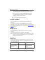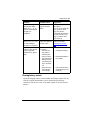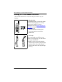
1
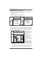
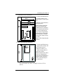
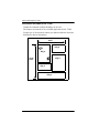
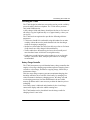
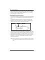
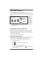
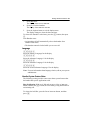
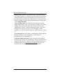
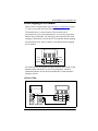
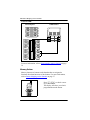
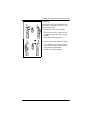
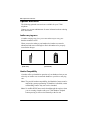
Part No. P0942257 04
Part No. P094225
T7406 Cordless Telephone
Installation Guide
Read all documentation before proceeding with installation of this
unit.
Warning: First-time battery charge
Follow this procedure for the first-time charge of your handset battery packs
and when you first set up your T7406 system. Failure to follow all of these
steps can result in operational difficulties.
Ensure that the battery pack is fully charged before you attempt to use your
T7406 handset for the first time.
• Charge the battery pack in the rear port of the charger for a
minimum of 30 minutes.
• Install the battery pack in the handset.
• Put the handset into the front port of the charger and charge the
battery pack in the handset for a minimum of three hours.
• Trickle charge a spare battery pack in the rear battery port of the
charger for 12 hours.
Ensure you configure the handsets in an orderly fashion. If you are
configuring a number of handsets, ensure the battery packs for all the
handsets are charged before you start configuring the handsets to the base
station.
Refer to Handset Configuration on page 27.
2/
© 2002, Nortel Networks, Nashville, TN 37228. ALL RIGHTS
RESERVED.
For further information, call your technical support team or a Nortel
Networks Sales representative.
Nortel, the Nortel globemark, Norstar, and Business Communications
Manager are trademarks of Nortel Networks. All other trademarks are
property of their respective owners. All information is subject to
charge. Nortel Networks reserves the right, without notice, to change
its products as progress in engineering or manufacturing methods or
any other circumstances may warrant.
P0942257 04
Contents / 3
Contents
Provisioning the T7406 . . . . . . . . . . . . . . . . . . . . . . . . . . . . . . . 7
Operational Bandwidths . . . . . . . . . . . . . . . . . . . . . . . . 7
Operational Parameters . . . . . . . . . . . . . . . . . . . 7
Installation Site Parameters . . . . . . . . . . . . . . . . . . . . . . 8
RF LANs (Radio Frequency Local Area Networks) . . 9
Telephone-to-Base Range . . . . . . . . . . . . . . . . . . . . . . . 9
Environmental Layout Considerations . . . . . . . . . . . . . 10
Environments Unsuitable for the T7406 . . . . . . 12
Powering the T7406 . . . . . . . . . . . . . . . . . . . . . . . . . . . 13
Battery Charge Controller . . . . . . . . . . . . . . . . . 13
Specifications . . . . . . . . . . . . . . . . . . . . . . . . . . . . . . . . 14
Important battery pack information . . . . . . . . . . . . . . . . . . . 15
About your T7406 telephone . . . . . . . . . . . . . . . . . . . . . . . . . . 16
Radio range and coverage considerations . . . . . . . . . . . 16
Security of Conversation . . . . . . . . . . . . . . . . . . . . . . . . 16
Density and Interference . . . . . . . . . . . . . . . . . . . . . . . . 16
Spare Parts . . . . . . . . . . . . . . . . . . . . . . . . . . . . . . . . . . 17
T7406 Parts Lists . . . . . . . . . . . . . . . . . . . . . . . 17
Handset Overview . . . . . . . . . . . . . . . . . . . . . . . . . . . . . . . . . . . 18
Handset Signal Detection . . . . . . . . . . . . . . . . . . . . . . . 19
Handset Features . . . . . . . . . . . . . . . . . . . . . . . . . . . . . . 20
Installing the Base Station . . . . . . . . . . . . . . . . . . . . . . . . . . . . 21
Base Station Features . . . . . . . . . . . . . . . . . . . . . . . . . . 21
Antenna . . . . . . . . . . . . . . . . . . . . . . . . . . . . . . . 21
Mounting Bracket . . . . . . . . . . . . . . . . . . . . . . . 22
T7406 Pre-installation Programming . . . . . . . . . . . . . . 22
Before you start . . . . . . . . . . . . . . . . . . . . . . . . . . . . . . . 23
Mounting and Connecting the Base Station . . . 23
T7406 Installation Guide
4 / Contents
Charging the T7406 Battery Pack . . . . . . . . . . . . . . . . . . . . . . .24
First-time Charging . . . . . . . . . . . . . . . . . . . . . . . . . . . .25
Handset Power . . . . . . . . . . . . . . . . . . . . . . . . . . . . . . . .26
Low battery . . . . . . . . . . . . . . . . . . . . . . . . . . .26
Recharge . . . . . . . . . . . . . . . . . . . . . . . . . . . . . .26
Battery levels . . . . . . . . . . . . . . . . . . . . . . . . . . .27
Handset Configuration . . . . . . . . . . . . . . . . . . . . . . . . . . . . . . . .27
Important First-time Installation Information . . . . . . . .27
Identifying the Handsets to the System . . . . . . .28
Assigning the Handset to the Base Station . . . .29
Using the Handset Display Buttons . . . . . . . . . . . . . . . .30
Configuring the First Handset to a Base Station . . . . . .30
Configuring the Handset ID Number . . . . . . . .30
Changing the Handset ID Password . . . . . . . . .31
Assigning the Security Code . . . . . . . . . . . . . . .32
Configure the next handset to the base station . . . . . . .33
Setting Handset Features . . . . . . . . . . . . . . . . . . . . . . . . . . . . . .33
Ring Type . . . . . . . . . . . . . . . . . . . . . . . . . . . . . . . . . . .33
Ringer Volume . . . . . . . . . . . . . . . . . . . . . . . . . . . . . . . .34
Lock Handset . . . . . . . . . . . . . . . . . . . . . . . . . . . . . . . . .34
Language . . . . . . . . . . . . . . . . . . . . . . . . . . . . . . . . . . . .35
Handset System Feature Notes . . . . . . . . . . . . . . . . . . .35
Button Mapping on the Handset . . . . . . . . . . . . . . . . . . . . . . . .37
Memory buttons . . . . . . . . . . . . . . . . . . . . . . . . . . . . . . .38
Programming memory buttons . . . . . . . . . . . . .39
Button Inquiry . . . . . . . . . . . . . . . . . . . . . . . . . .40
System Feature codes . . . . . . . . . . . . . . . . . . . .40
Handset Asleep (Save Battery Mode) . . . . . . . . . . . . . .41
Handset Asleep Mode Feature Conditions . .41
Make and Answer Calls . . . . . . . . . . . . . . . . . . . . . . . . . . . . . . .42
Make a call . . . . . . . . . . . . . . . . . . . . . . . . . . . . . . . . . . .42
Answer calls . . . . . . . . . . . . . . . . . . . . . . . . . . . . . . . . . .42
P0942257 04
Contents / 5
Hold calls . . . . . . . . . . . . . . . . . . . . . . . . . . . . . . . . . . . 43
Mute microphone . . . . . . . . . . . . . . . . . . . . . . . . . . . . . 43
Page . . . . . . . . . . . . . . . . . . . . . . . . . . . . . . . . . . . . . . . . 43
Customize a handset . . . . . . . . . . . . . . . . . . . . . . . . . . . . . . . . . 44
Backlight On/Off . . . . . . . . . . . . . . . . . . . . . . . . . . . . . 44
Helpful hints . . . . . . . . . . . . . . . . . . . . . . . . . . . . . . . . . . . . . . . 44
Cleaning battery contacts . . . . . . . . . . . . . . . . . . . . . . . 45
Installing the T7406 Handset Accessories . . . . . . . . . . . . . . . . 46
Optional accessories . . . . . . . . . . . . . . . . . . . . . . . . . . . . . . . . . 48
Leather carrying cases . . . . . . . . . . . . . . . . . . . . . . . . . . 48
Headset Compatibility . . . . . . . . . . . . . . . . . . . . . . . . . 48
Headset installation . . . . . . . . . . . . . . . . . . . . . . 49
Regulatory information . . . . . . . . . . . . . . . . . . . . . . . . . . . . . . . 50
Canadian Regulations . . . . . . . . . . . . . . . . . . . . . . . . . . 50
US Regulations . . . . . . . . . . . . . . . . . . . . . . . . . . . . . . . 50
Federal Communications Commission (FCC)
Notice . . . . . . . . . . . . . . . . . . . . . . . . . . . . . . . . 50
EMI/EMC (FCC Part 15) . . . . . . . . . . . . . . . . . . . . . . 51
For Class A Host equipment . . . . . . . . . . . . . 51
For Class B Host equipment . . . . . . . . . . . . . 52
Safety . . . . . . . . . . . . . . . . . . . . . . . . . . . . . . . . . . . . . . 52
Important Safety Instructions . . . . . . . . . . . . . . . . . . . . 52
Installation . . . . . . . . . . . . . . . . . . . . . . . . . . . . . . . . . . . 53
Use . . . . . . . . . . . . . . . . . . . . . . . . . . . . . . . . . . . . . . . . 53
T7406 Installation Guide
6 / Contents
P0942257 04
Provisioning the T7406 / 7
Provisioning the T7406
This chapter provides specification and provisioning information for
the T7406 cordless system.
The T7406 is a Frequency Hopping Spread Spectrum (FHSS) cordless
telephone. The benefits of this technology are: improved range,
robustness and, less susceptibility to interference, fading and multipath.
The use of a common wall-mounted base station for multiple handsets
allows you to position the base antennas for maximum performance and
coverage. The indoor range of the T7406 is 95 meters (300 feet) in a
typical office environment. This range may vary with differing
environments.
Operational Bandwidths
The T7406 cordless telephone operates in the ISM (Industrial,
Scientific, and Medical) 902-928 MHz band. The T7406 divides the
ISM band into two sets of operating frequencies to allow the
coexistence of other ISM devices. Examples of these products are SKU
scanners and remote controls for products such as garage door openers
and home theatre systems. Note that, since the T7406 is a frequency
hopper, it uses at least half of the available frequencies in the ISM band
for operation and can make it difficult for other 900 MHz devices to
operate correctly. The following table identifies the frequencies used
for the upper and lower bands of operation:
• Lower: 902 - 915 MHz
• Upper: 915.1 - 928 MHz
These bands are selectable for each base station through dip switches
located on the back of the T7406 base station. Each base station
supports up to three handsets. Selection of the correct band for
operation may minimize interference between devices.
Operational Parameters
For example, with a configuration of six handsets, two base stations are
required (three handsets per base station). One base station will be set to
the upper band, and the other base station will be set to the lower band.
T7406 Installation Guide
8 / Provisioning the T7406
Another example is an environment that already contains another 900
Mhz device (e.g. a scanner with 900 Mhz wireless connection to a
LAN). In this environment, only one T7406 base station should be
installed. Set the T7406 base station dip switch to the opposite band
that the scanner is operating in.
Installation Site Parameters
Physical characteristics of the site where the T7406 is to be installed, or
has been installed, must be evaluated to maximize the performance of
the T7406 telephone. Outlined below are some of the most common
characteristics to be considered:
• wood vs. metal construction
• metal vs. wood studs in wall construction
• thickness of concrete floors and walls (and type of covering, e.g.
Metallic wall paper)
• number of floors and walls
• open office (cubicles) vs. closed office (floor to ceiling)
• steel partitions, elevator shafts, electric utility rooms
• RF LANs (Radio Frequency Local Area Networks), extensive
machinery, computer equipment, and other cordless phones or
wireless devices
Placement of the antenna is crucial for enhancing the performance of
the T7406. Pick a central location and mount the antenna with the
following guidelines:
• Attach the base station at least eight feet from the floor.
• Minimize the number of walls between the base station and handsets.
• Centralize the location of the base station to make the number of
interfering walls equal in all directions.
• Do not mount the base station on an outside wall.
• Do not mount or place the base station outdoors.
• Adjust the antenna for optimal transmission by moving it through 90degree angle planes (i.e. perpendicular to the wall, parallel to the
wall, perpendicular to the floor, parallel to the floor)
P0942257 04
Provisioning the T7406 / 9
RF LANs (Radio Frequency Local Area Networks)
RF LANs are primarily installed in large chain businesses such as retail
and grocery where the RF LAN is used for inventory equipment.
With the correct selection of the T7406 operating band, the RF LAN
operating at 900 MHz does not pose an operating issue for T7406 nor
does the T7406 pose issues for the RF LAN with respect to data
transmission capabilities. However, there may be instances where the
T7406 user may hear an occasional slight audio click when operating in
a RF LAN environment. This should not inhibit the user's ability to
hold a normal two-way conversation using the T7406.
Telephone-to-Base Range
The T7406 cordless telephone utilizes an extremely efficient radio
design to deliver the maximum possible range while complying with
the governing rules of the Federal Communications Commission (FCC)
and Industry Canada. The effective operating range within a site will
largely depend on the environmental characteristics mentioned
previously, such as building construction and internal layout of the site.
Typically, the T7406 will provide an effective operating range of 95
meters (300 feet).
If the T7406 is not meeting this operating range, the following are some
steps that can be taken to assist with the troubleshooting:
• Check surroundings for any other product that my be causing
interference.
• Check environment for obstructions that may be limiting the range.
• Change the orientation of the base station antenna.
• Move the base station to another location.
• Select the alternate operating band of the T7406.
It is important to keep in mind that, based on environmental
characteristics, the T7406 may not be the optimum solution for all
users. If the desired level of mobility performance is not met, contact
your authorized Nortel Networks distributor to discuss alternatives.
T7406 Installation Guide
10 / Provisioning the T7406
Environmental Layout Considerations
The following facility layouts are examples of reference building
footprints for which the T7406 is most suited.
1. The Storefront
• under 929 square meters/10,0000 square feet
• Open environments with few interior barriers
30.5 m/100 ft.
30.5 m/
100 ft.
Diagonal
measurement
is
44 m/ 144 ft.
46 m/150 ft.
46 m/
150 ft.
Diagonal
measurement
is
55 m/180 ft.
2. Office Facility
The T7406 can also be used in business with larger square footage and
including an interior layout that has a higher concentration of physical
barriers. Full radio coverage at these facilities takes more planning to
work around possible barriers.
• Professional office
46 m/150 ft.
• Typically under 2,323
square meters/25,000
square feet.
• Usually mix of open
and closed offices
46 m/
• Typical office floor
150 ft.
with elevator shaft and
utility rooms in core of
facility.
Some transmission path
loss will occur when the
base station and the
handset are separated by physical barriers, as represented by this
core area.
The amount of path loss is dependent upon the number of walls
and type of material and density of barriers utilized in the core
area.
1
4 GHI
7 PQRS
P0942257 04
2 ABC
3 DEF
5 JKL
6 MNO
8 TUV
9 WXYZ
0
#
Provisioning the T7406 / 11
3. Combination Office/Warehouse
• Various Small Businesses
• Typically under 1,394
square meters/15,000 square
feet
• Mixture of closed offices
and open spaces
Typical facility with both
office and warehousing
combined in one operation.
Some transmission path loss
in expected with the presence of dense firewall and
racking/shelves filled with
dense materials. Consider
placing base station in largest room.
Range will be limited in this
situation.
30.5 m/
100 ft.
61 m/
200 ft.
1
4 GHI
7 PQRS
2 ABC
3 DEF
5 JKL
6 MNO
8 TUV
9 WXYZ
0
#
4. Office with adjacent yard area(s)
95 m/
300 ft.
1
4 GHI
7 PQRS
2 ABC
3 DEF
5 JKL
6 MNO
8 TUV
9 WXYZ
0
#
• Various small businesses
• Typical office facility 465
to 929 square meters.
(5,000 to 10,000 sq. ft.)
• Adjacent open space or
yard next to office
•Radio transmission will be
relatively unimpaired in
more open environments as
path loses due to barriers
such as walls and objects
are minimized.
This environment may allow for ranges in excess of 95 m
(300 ft.).
T7406 Installation Guide
12 / Provisioning the T7406
Environments Unsuitable for the T7406
Campus Environment (multiple buildings on one site)
The campus environment is not a suitable application for the T7406.
For this type of environment, contact your authorized Nortel Networks
distributor to discuss alternatives.
95 m/
300 ft.
Bldg. B
Bldg. A
107 m/
350 ft.
1
4
2
GHI
7 PQRS
5
ABC
3
DEF
JKL
6 MNO
8 TUV
9 WXYZ
0
#
Bldg. C
Bldg. E
P0942257 04
Bldg. D
Provisioning the T7406 / 13
Powering the T7406
The T7406 design has taken into account the need to provide a reliablypowered cordless business telephone. The T7406 utilizes premium
1400 mAh NiMh batteries.
A fully charged 1400 mAh battery should provide four to five hours of
talk time in a typical eight-hour day over, approximately, a three-year
service life.
The T7406 has been engineered to provide the following talk-time
parameters:
• T7406 users should feel comfortable using the handset for an entire
workday without the need to put the handset back into the charger
cradle for charging or topping up.
• Studies have shown that users have been able to get four to five hours
of talk time from a fully charged 1400 mAh battery.
• Traffic studies have shown that typical users do not usually need
more that three hours of talk time in an eight-hour day.
• If talk times exceed four hours or the product is to see use through
multiple, consecutive shifts, multiple spare batteries are strongly
recommended.
Battery Charge Controller
The T7406 incorporates a special handset battery charge controller that
employs a four-stage charging program that sequences charging from a
soft start to a fast charge, and then to a topping charge, followed by a
maintenance charge.
This four-stage charge sequence presents an optimum-charging plan
that helps maximize the overall life of the battery by managing two
critical elements in the battery charging process, the charge rate and
overcharging protection. Note that NiMh batteries do not exhibit
memory problems and it is not necessary to drain the batteries prior to
recharging.
Low battery status is indicated on the handset by the visual charge
status on the display and/or the audible warning tone.
The T7406 handset can be placed back into the charge cradle for
charging when it is not in use.
T7406 Installation Guide
14 / Provisioning the T7406
• A fully depleted 1400 mAh battery will be restored to full charge in
three hours.
• The handset charge light will turn from red to green to indicate that
the handset battery is fully charged and ready for use.
• The T7406 charge stand provides a rear port as a trickle charger that
charges a fully depleted 1400 mAh battery in 12 to 14 hours.
Specifications
Frequency band
Half of the 900 MHz ISM band:
either 902 to 915 MHz or 915.1 to 928 MHz
Total channel
capability
Spread spectrum frequency hopping is
available on 27 channels per base
Handset dimensions Length: 170 mm/6.8 inches (without antenna)
Width: 58 mm/2.32 inches
Overall Thickness: 40 mm/1.60 inches
Handset range
Typical range of 95 m/300 feet, depending on
the physical environment
Handset weight
280 g/9.38 oz. (with battery pack)
Battery Pack
Capacity: 1400 mAh, 3.6 V
Talk Mode: up to five hours (with backlight
OFF)
Standby Mode: up to 72 hours
Base dimensions
Length: 150 mm/6 inches
Width: 160 mm/6.4 inches
Height (front): 28 mm/1.12 inches
Height (rear): 34 mm/1.36 inches
Base power
Input: 110 VAC, 60 Hz
Output: 9 VDC, 600 mA
P0942257 04
Important battery pack information / 15
Important battery pack information
Before you use the T7406 cordless handset, read the following
information.
This unit contains a rechargeable nickel metal hydride battery:
• Follow the proper installation and charging procedures for the
T7406 battery pack. Refer to Charging the T7406 Battery Pack on
page 24.
• The rechargeable battery pack must be fully charged before you use
the T7406 handset for the first time.
• It takes approximately three hours to charge a standard 1400 mAh
battery pack.
• It takes approximately 12 hours to trickle charge the spare battery in
the charging cradle.
Warning:
•
The battery will explode if disposed of in a fire.
•
Do not use the nickel metal hydride batteries provided
with your T7406 cordless telephone with any other
product. These batteries were designed specifically for
use with theT7406 telephone and the T7406 charger
ONLY. Improper use of the T7406 batteries may result in
fire hazard.
•
Do not do anything that would cause the battery to short
circuit.
•
Do not charge the battery with any charger other than the
one supplied with this equipment.
WARNING
Nickel metal hydride batteries must be disposed of
properly.
Do not dispose of the batteries in office or household
waste.
Nickel metal hydride batteries are recyclable. You can help preserve the
environment by returning your unwanted batteries to your nearest
recycling center for recycling or proper disposal.
Phone 1-800-8-BATTERY to locate a Battery Recycling Center near
you.
T7406 Installation Guide
16 / About your T7406 telephone
About your T7406 telephone
The T7406 is a multiple-handset, single-base cordless telephone
system. The T7406 telephone provides a fully-integrated mobility
solution for your business. The T7406 handset allows you to freely
move around your work space while on a call, and still maintain access
to all your telephone system features.
The T7406 telephone uses advanced digital frequency hopping spread
spectrum (FHSS) technology to provide a quality audio path over a 900
MHz radio link. Establishing a call over a radio link is comparable to a
wire line communication.
Note: The T7406 cordless telephone is supported on all Norstar systems
(DR3 or higher) and on all Business Communications Manager
systems.
Radio range and coverage considerations
The effective operating radio range in your facility depends on the
building construction and the internal layout of the facility. Typically, a
dense office or warehouse environment has an effective operating radio
range of 95 meters (300 feet). An open office environment enhances
operating radio ranges. Refer to Provisioning the T7406 on page 7.
Security of Conversation
Each base station has a unique Security Code (S.S. Code). All three
handsets registered to the base station must share the same Security
Code. Each of the three handsets assigned to a base station must also
have a unique identification (Set I.D. 1, 2 or 3).
Density and Interference
For this system to be interference-free, install a maximum of two base
stations and six handsets per location. Each base station provides three
independent time compression multiplexing (TCM) line connections to
the telephone system.
Each base station uses half of the Industrial Scientific Medical (ISM)
band for its frequency hopping channels. The dip switches on the base
station allow you to assign the base station to use either the lower half
(902-915 Mhz) or the upper half (915.1-928 Mhz).
P0942257 04
About your T7406 telephone / 17
Each base station must use a separate ISM half band. For more
information about setting the dip switches, refer to Installing the Base
Station on page 21.
If other devices operating on the ISM band interfere with the T7406
base, the other half of the band may be used to try to minimize
interference. In this situation, install only one base station and three
handsets per location.
Spare Parts
You can order spare parts for your T7406 telephone. For more
information about spare parts, refer to T7406 Parts Lists on page 17.
For more information about accessories, refer to Optional accessories
on page 48. For more information about ordering, contact your system
administrator.
T7406 Parts Lists
Along with this guide, the following items are included with the T7406
telephone.
System parts list
Mounting bracket
Base station and Mounting Bracket
Power
adapter
Telephone cord
(3)
T7406 Installation Guide
18 / Handset Overview
Handset parts list
®
≥
1
2 ABC
4 GHI
5 JKL
6 MNO
8 TUV
9 WXYZ
0
#
7 PQRS
3 DEF
Handset
Charger
Handset card (2) and Plastic lens (1)
Battery pack
(2)
Power
adapter
Belt clip
Wrist strap
Handset Overview
The handset automatically links with the base station by searching for
the base station signal when the following are completed:
• battery is charged
• base station and handset are powered
• handset identification is configured
• base station Security Code is assigned
P0942257 04
Handset Overview / 19
Handset Signal Detection
You can monitor the handset signal strength while moving to different
locations. The antenna/signal strength and battery icons appear on the
handset display.
When you move too far from the base station, the following occurs on
the handset:
• the antenna/signal strength icon disappears
• Out of range... message appears
• handset produces an intermittent beep
• handset may go into scanning mode
If the signal strength is weak, move back into range to stop the handset
display messages and warning tones.
If you go completely out of range during an active call, the call is
automatically placed on hold. For more information, refer to Hold calls
on page 43. Retrieve a held call by selecting the flashing red line button
when you are back in range.
Note: In cases where the line button does not light when you move back
into range of the base station, press the intercom/line button that
the call came in on, to take the call off hold.
T7406 Installation Guide
20 / Handset Overview
Handset Features
Antenna
Light collar
Flashes during ringing
calls.
Display
Shows the time, date, call
information, handset status
icons and guides you while
using features.
Memory and line
buttons
Buttons for one touch
dialing, feature
operations, line
access or answering
a line.
Display buttons
Starts or cancels a feature.
Cancels active calls.
Places calls on hold.
®
1
Headset port
4
GHI
7 PQRS
≥
2 ABC
3 DEF
5
JKL
6 MNO
8 TUV
9 WXYZ
0
#
Lanyard anchor
(hook)
For attaching a
wrist strap.
Microphone
Volume control
Dialpad
Battery Pack
P0942257 04
Options
button/Mute
Answers
calls, Mute the
microphone
on an active
call and
accesses the
Options List.
Installing the Base Station / 21
Installing the Base Station
This section describes the base station and:
• how to mount the base station on a wall
• what programming is required before you connect the base station to
your system
• how to connect the base station to your system
The T7406 cordless telephone operates on the same principle as a twoway radio. Therefore, the location of the base station affects the range
of reception. The base station should not be installed where radio waves
are blocked or reflected, such as next to a filing cabinet.
For optimal performance, install the base station at least 2.4 meters
(eight feet) above the floor. Always position the antenna at a 90° angle
to the base station.
Base Station Features
This section illustrates the base station for the T7406 system.
Antenna
Base
antenna
(90° to base
station)
LED indicates base
station has power
Note: When power is connected to the base station, the LED on the
front of the unit starts flashing. During operation the LED flashes
every second to indicate that the unit is receiving power.
T7406 Installation Guide
22 / Installing the Base Station
Mounting Bracket
Mounting
bracket
Notches match to bracket.
T7406 Pre-installation Programming
Before connecting the T7406 base station to your system, you must set
up system programming for the handset lines.
Have the system administrator set up this programming:
1. Program Handsfree to Auto.
2. Program a maximum of three lines to each handset.
3. Assign Ring & Appear on the lines you assign to the handset.
Note: Appear only does not allow the handset to wake from
Handset Asleep mode.
4.
Set the Page zone to None.
Note: Handsets can send Page announcements, but they cannot
receive them.
5.
Set DND on Busy to Yes if you do not want your calls
interrupted with a ring tone when a second call comes in. Instead,
the button flashes, indicating an incoming call.
Other telephone programming is the same as for the M7310
telephone, with the exception of the memory key locations.
6.
P0942257 04
Installing the Base Station / 23
Before you start
• Ensure there is an AC power outlet within 1.5 meters (5 feet) of the
base station location.
• Ensure that the telephone lines from your system have been installed
to the base station location.
Mounting and Connecting the Base Station
Follow these steps to mount and connect each base station.
1. Use the mounting bracket as a template to position the base
station and mark the screw positions.
2. Use screws to attach the mounting bracket to a wall or ceiling.
3. Set the base station dip switches, located on the back of the base
station, to the required ISM frequency band.
123
Upper half
ISM Band
Lower half
ISM Band
4.
• On the first base station you install,
set the dip switches to operate in the
upper half of the ISM band. From left
to right, set to Down-Up-Down.
• On the second base station, set the dip
switches to operate in the lower half
of the ISM band. From left to right,
set to Down-Down-Up.
Connect the telephone lines to the base station.
a. Plug one end of the line cord into a
telephone jack on the base station.
b. Connect the other end into a telephone
port on the system equipment.
Note:Connect a maximum of three
TCMs per base station to the system.
c. Plug the small end of the power
adapter into the back of the base
station.
d. Plug the other end into an AC outlet.
Note:A red light flashes continuously
on the base station when powered.
T7406 Installation Guide
24 / Charging the T7406 Battery Pack
5.
6.
Align the notches on the back of the base station with the
mounting bracket on the wall.
Push the base station against the brackets until they are securely
connected.
For the best radio reception, make
sure the antenna on the base station
is always at a 90° angle to the base
station.
Charging the T7406 Battery Pack
Warning: It is imperative that you follow the steps in this section when
you first initialize a base station and configure the first handset.
Follow these steps to set up the charging unit:
1. Plug the small end of the power
adapter into the back of the
charger.
2. Plug the power adapter into an
AC outlet.
The back port (battery port) on the
charger is used to charge the battery
pack on its own.
The front port supports the handset
with an installed battery pack.
The rechargeable battery pack must be fully charged before you use
your T7406 handset for the first time.
Note: Multiple handsets — If you are installing a number of handsets
at once, follow these instructions for each handset before you
start trying to configure the handsets to the base station.
P0942257 04
Charging the T7406 Battery Pack / 25
First-time Charging
When you first setup your new handset, follow these steps to charge the
battery and install it into the handset:
1.
Charge the battery pack in the back battery port of the charger for
a minimum of 30 minutes.
2. Install the battery pack in the handset.
3. Charge the battery pack in the handset for a minimum of three
hours.
4. Trickle charge a spare battery pack in the back battery port of the
charger for 12 hours.
The following diagrams demonstrate where the battery pack fits onto a
handset, and how to trickle charge the spare battery pack.
Installing a Battery Pack into the Handset
1. Position the battery pack in the
bottom position on the back of the
Battery
handset.
pack
2. Snap the top of the battery pack into
place.
Charging the Handset
Note: If you
1. Slide the handset into the charger.
are using a
Make sure the handset and charger
leather cover,
contacts touch.
it must be
2.
The handset charge indicator light
removed
turns
on. The battery pack indicator
before you
light
is
red while it is charging.
put your
The
battery
pack fully charges in
handset in
approximately
three hours. When
charger.
the battery pack is fully charged, the
indicator light turns green.
Note: Charging begins as soon as
the handset is placed in the base
station.
3. Slide the spare battery pack into the
back battery port. Make sure the
battery pack and charger contacts
Indicator lights
touch.
T7406 Installation Guide
26 / Charging the T7406 Battery Pack
Note: Make sure the battery is properly installed in the handset or
seated in the charger. If the T7406 battery is not properly
installed, or if the battery level is extremely low, the six
programmable buttons may light or flash simultaneously. This
may also happen when the handset is in the charger.
Exchange the handset battery pack regularly (once a week) if
you have a second (spare) battery pack.
The spare battery pack trickle charges in approximately 12
hours. When the spare battery pack is fully charged, the
indicator light turns green.
Handset Power
Power to the handset comes from the battery pack installed in the back
of the handset. When the battery pack power level is low it must be
recharged in the charging unit.
Low battery
When the power is low, a tone sounds every 15 seconds indicating you
need to recharge the battery soon. Your call is automatically put on hold
20 seconds after the battery pack runs out.
Recharge
Recharging begins as soon as you put the handset in the charging unit.
Refer to Charging the T7406 Battery Pack on page 24.
• Be sure that the handset and charger contacts touch. A red LED
indicates the battery is charging.
• To fully recharge the battery pack, leave the handset in the charger
until the indicator light turns green.
Note: If the T7406 battery is not properly installed, or if the battery
level is extremely low, the six programmable buttons may light or
flash simultaneously. This may also happen when the handset is
in the charger.
P0942257 04
Handset Configuration / 27
Battery levels
The following icons appear on the display.
Indicates battery pack is fully charged.
Indicates battery pack is 2/3 charged.
Indicates battery pack is 1/3 charged.
Indicates battery pack is completely
discharged.
Note: The battery level icons show approximate charge status values.
You can talk continuously for up to five hours on the handset with a fully
charged 1400 mAh battery pack. A fully charged battery pack has a
standby time up to 72 hours. Using the backlight shortens talk and
standby time.
Handset Configuration
This section describes how to set up handsets on a base station. Note
that there is one extra step for setting up the first handset on a new base
station.
Important First-time Installation Information
When performing the initial configurations on the handset, ensure that
all the handsets you intend to configure have fully-charged battery
packs installed.
Since the handsets start scanning as soon as they are powered, you must
set the handset ID #s first when you configure the handset to avoid
conflicts between handset signals and the possibility of one set
mirroring another.
T7406 Installation Guide
28 / Handset Configuration
If you install more than one base station on a system, ensure that you
assign a unique Security code to each base station. However, all base
stations have the same three Handset ID numbers (1, 2, or 3), which
identify the handset to the base station.
Identifying the Handsets to the System
Each of the three handsets registered to a base station share an identical
Security code, but each handset has a unique handset ID number of 1, 2,
or 3.
The handset ID number the handset is assigned to maps back to the
TCM/RJ-11 jack on the back of the base station. The diagram below
identifies which jack supports which handset ID number.
Handset ID 1
Handset ID 2
1
2
Handset ID 3
3
In turn, these numbers correspond to telephone records in the main
system. In the system, these records identify each telephone with a local
number, referred to as a DN (directory number). Since the records will
be set up before you configure your handset, check with your system
administrator to determine which local has been assigned to which port.
From there, you can identify which Handset ID number should be
assigned to each handset.
Note: When a base station is relocated, the Handset ID number follows
the set DN (system telephone record), if the Set relocation feature
is on.
P0942257 04
Handset Configuration / 29
Assigning the Handset to the Base Station
When you assign the first handset to a base station, you must send the
security code to the base station. For subsequent handsets, you only
need to identify the security code on the handset itself. This is
explained in detail in later sections.
This is the general process for setting up a T7406 handset:
• Identify the handset to a unique Handset ID # (1, 2, or 3)
Note: The handset ID #, which gets assigned to each handset,
matches up to TCM/RJ-11 jack on the back of the base .
station. Ask your system administrator which handset ID
maps to which set DN on the system.
• Change the default password for selecting a handset ID (default:
000000)
• Assign a Security code (S.S. code)
• Send the Security code from the handset to the base station
Note: Sending the security code to the base station is only
performed for the first handsets. For subsequent handsets,
you need only identify the security code on the handset.
• Assign the ring type
• Assign the ringer volume
• Assign the language that appears on the handset display
T7406 Installation Guide
30 / Handset Configuration
Using the Handset Display Buttons
The T7406 handset has a three-line display.
The three display buttons located under the display are used to interact
with the handset menus and the feature code messages that appear on the
display.
• The first line of
Ring Again?
Feature message the display
shows handset
NO
EXIT
YES
Button label
messages and
Display icons
menu items.
• The second
line displays
Display button
button labels in
capital letters.
• The third line displays the antenna/signal strength icon and the
battery charge icon.
Configuring the First Handset to a Base Station
When you configure a handset to a new base station, you must ensure
the base station receives the assigned security code. For subsequent
handsets, the security code must be identical, but it does not need to be
re-assigned to the base station.
Other settings are the same for all handsets.
Configuring the Handset ID Number
Each of the three handsets registered to a base station share an identical
Security code, but each handset has a unique Set ID of 1, 2, or 3.
Follow these steps to set the handset ID and new password:
1. Press the Options button.
2. Press SHOW.
3. Press NEXT until the display shows 6. Handset ID.
4. Press SHOW.
The display shows the current Handset ID #.
• If this is the correct number, press OK and continue with
the next section.
P0942257 04
Handset Configuration / 31
• If you want to change the number, follow these steps:
a. Press CHANGE.
The display shows Enter Password. (six digits)
b. Enter the default password (000000).
c. Press OK to accept the code.
The display shows Press Digit 1 - 3. The current
Handset ID # is displayed on the bottom left of the
LCD.
d. Press the digit that you want to assign to this handset.
e. Press OK.
The display shows 6. Handset ID.
Changing the Handset ID Password
After you enter the handset ID, if you want to change the password for
the ID access, follow these steps:
1.
Press NEXT until the display shows 7. Chg Password.
Note: This password is used to access the Handset ID option. If
you decide not to change the password, press the Option
button to exit the menu.
2.
Press SHOW.
The display shows Enter old PWD.
3.
Enter the default six-digit password (000000) or the last password
you entered.
4.
Press OK.
The display shows Enter New PWD.
5.
Enter a new six-digit password.
Note: For ease of administration, it is recommended that you use
the same password as the one you used for the Security
code/S.S. Code.
T7406 Installation Guide
32 / Handset Configuration
6.
7.
8.
9.
Press OK.
The display shows Confirm New PWD.
Re-enter the password.
Press OK.
The display shows PWD Changed!.
Press the Options button to exit the Option menu
The display changes to show the date and time.
Password errors
If you enter an incorrect password and the display shows PWD Error!,
return to the 7. Chg Password menu item and try again.
Lost password
Make a note of the new password. If you forget your password, you will
need to contact your Distributor for help to unlock the set.
Assigning the Security Code
After you assign the handset ID # to a handset, you need to configure
the handset to a base station.
Follow these steps to assign a Security code to the handset.
1. Press the Options button.
2. Press SHOW.
3. Press NEXT until the display shows 4. Set S.S. Code :.
4. Press CHANGE to assign a security code to the handset. The display
shows Enter Password.
5. Enter the six-digit password (default 000000).
6. Press OK. The display shows Press 6 digits.
7. Enter the six-digit Security code.
The display changes to show the code as entered.
8. Press OK to accept the code.
The display shows 4. Set S.S. Code :.
If you are assigning a handset to an existing base, your handset is now
connected to the system.
P0942257 04
Setting Handset Features / 33
If you are assigning the first handset to a new base station (which has
no security code), continue with the following steps:
9. The display shows 4. Set S.S. Code :, press NEXT to get ready to
send the security code to the base station.
The display shows 5. Send S.S. Code.
10. Unplug the AC power adapter connected to the base station, and
plug it back in again.
11. Within 15 seconds, press and hold the OK button for five seconds.
This sends the Security Code to the base station. The display
shows Send OK! and you hear a beep when the transfer is
successful.
Note: If the Security Code transfer fails, the display shows Send
Error! To correct this, repeat steps 9 and 10.
12. Press the Options button to exit the Option menu.
The display changes to show the date and time.
Configure the next handset to the base station
Configure the second and third handsets to the base station using these
procedures:
1.
Follow the steps in Configuring the Handset ID Number on page
30. Ensure you enter a different handset ID number (1, 2, or 3)
for each handset you configure.
2.
If you want to change the handset ID password, continue with the
steps in Changing the Handset ID Password on page 31.
3.
Once you have assigned a Handset ID #, continue with Assigning
the Security Code on page 32 up to and including step 8.
Setting Handset Features
After you identify the handsets to the base station, you can set up the
handset features:
Ring Type
To assign the ring type:
T7406 Installation Guide
34 / Setting Handset Features
1.
2.
3.
4.
5.
6.
Press the Options button.
Press SHOW.
The display shows 1. Ring Type.
Press SHOW. The display shows Ring Type :1.
Note: There is also a Ringer Off setting.
Press CHANGE to listen to the four different rings available on your
handset.
Press OK to accept the ring type of your choice.
Press the Options button to exit the Option menu.
The display changes to show the date and time.
Note: Ring Type can only be set through the Option menu on the
handset. This feature cannot be set in system programming.
Ringer Volume
You can assign the ringer volume level for the handset. The ringer
volume level assignment also affects the listening volume level.
To assign the ringer volume:
1.
2.
3.
4.
5.
6.
7.
Press the Options button.
Press SHOW.
Press NEXT until the display shows 2. Ringer Volume.
Press SHOW. The display shows Press Volume Bar.
Press the volume bar on the left side of the handset. There are
three ring volumes.
Press OK. The display shows 2. Ringer Volume.
Press the Options button to exit the Option menu.
The display changes to show the date and time.
Lock Handset
You can lock the buttons on the handset to prevent unintentional
dialpad or button presses.
To assign the Lock Handset feature:
1. Press the Options button.
2. Press SHOW.
P0942257 04
Setting Handset Features / 35
Press NEXT until:
The display shows 3. Lock Handset.
4. Press OK to lock the handset.
The display shows Handset Locked.
5. Press the Options button to exit the Option menu.
The display changes to show the date and time.
To release the Handset Locked state, press the ® button, then press
•.
Lock Handset notes:
• An incoming call will automatically release the handset from
Handset Lock mode.
• The handset cannot be locked while you are on a call.
3.
Language
≤•fi‚⁄
Select the Primary Language for the display.
≤•fi‚¤
Select the Alternate Language 1 for the display.
≤•fi‚‹
Select the Alternate Language 2 for the display.
≤•fi‚›
Select the second Alternate Language 3 for the display.
Note: For more information about language choices, talk to your system
administrator.
Handset System Feature Notes
The following section provides some notes about system features that
the handset has specific applications with.
Ring Notification: If the set is idle and you press a line or intercom
button, and then the ≥ button, the set will not get ring notification of
an incoming call.
To release the held line, press the line or intercom button, and then
press ® .
T7406 Installation Guide
36 / Setting Handset Features
Priority call: If a Priority call is made to your T7406 telephone that
does not have DND active, and the call is answered but the originating
caller then releases the call, you must still press an intercom line and
the ≥ button before the line is actually released. If you choose not to
do this, the handset stops providing ring notification of incoming calls,
refer to Ring Notification.
Voice Call Deny (F88): This feature has been purposely set as the
default for the handset, since voice calls cannot be made to the T7406
handset. If this setting inadvertently gets turned off by the system
administrator or the user, someone attempting to make a voice call to
the handset may not receive the No Voice Call display on their
telephone. As well, the call will continue as a normal call to the T7406
set.
LCD Contrast Level: This feature is not adjustable, either through the
handset or through system programming. Contrast has been
automatically set to an optimum level.
T7406 and M7410 interaction: If there are any M7410 telephones
installed on the system, you can attach only one base station and three
handsets in the same area. In this case, the base station must be set to
the upper band. Refer to Installing the Base Station on page 21 for
instructions about setting the base station to the lower band.
P0942257 04
Button Mapping on the Handset / 37
Button Mapping on the Handset
When you have completed the steps in Handset Configuration on page
27, then, you can map the feature buttons on your set.
The handsets have six feature buttons. These buttons can be
programmed by your system administrator. You can also program the
buttons from your handset. The following section describes the usual
mapping of the buttons, based on the M7310 telephone button mapping.
The illustration below shows examples of the default button mapping
for the handset.
Line 1
Last No.
Line 2
Voice call
Call Fwd
Intercom
The following two illustrations show the correlation between the T7406
handset buttons and the M7310 and T7316 telephones, which are
standard telephones used for Norstar and Business Communications
Manager systems.
M7310 to T7406
M7310 Telephone
T7406 Handset
T7406 Installation Guide
38 / Button Mapping on the Handset
T7316 to T7406
T7316 Telephone
T7406 Handset
31
33
24
26
23
25
27
29
11
13
15
01
02
03
04
05
17
19
21
06
07
08
09
10
For more information, refer to Programming memory buttons on page
39.
Memory buttons
Memory buttons are buttons on the handset that are assigned to
functions other than Intercom or line buttons. For more information,
refer to Button Mapping on the Handset on page 37.
Press ≤ •‚to check a memory or line button.
The display will show you what is
programmed onto the button.
®
1
4
7 PQRS
P0942257 04
≥
2 ABC
GHI
5
3 DEF
JKL
6 MNO
8 TUV
9 WXYZ
0
#
Button Mapping on the Handset / 39
Programming memory buttons
You can program memory buttons with:
• external autodial numbers
• internal autodial numbers
• features
After you have programmed the memory buttons, record the names and
numbers on the handset card. For more information, refer to Installing
the T7406 Handset Accessories on page 46.
External autodial
To program an external autodial memory button:
1.
2.
3.
4.
5.
Press ≤•⁄.
Press a memory button.
Dial the external number.
Press OK to store the number.
Label the button.
Internal autodial
To program an internal autodial memory button:
1.
2.
3.
4.
5.
Press ≤•¤.
Press a memory button.
Dial the internal number.
Press OK to store the number.
Label the button.
Features
To program a feature memory button:
1.
2.
3.
4.
5.
Press ≤•‹.
Press a memory button.
Press ≤ and enter the feature code.
Press OK to store the feature code.
Label the button.
T7406 Installation Guide
40 / Button Mapping on the Handset
Refer to System Feature codes on page 40 for a list of the most common
features. Your system administrator can also provide a list of all the
feature codes that are available.
Erase memory buttons
To erase a memory button:
1.
2.
3.
Press ≤•⁄.
Press the memory button you want to erase.
Press OK to erase the button.
Button Inquiry
Use the Button Inquiry feature to determine what is programmed on the
memory buttons on your handset.
To use the Button Inquiry feature from the handset:
1.
2.
3.
Press ≤•‚.
Press the button(s) you want to check, and read the display.
Press ≤or ® when you are finished.
System Feature codes
Contact your system administrator for information about all the feature
codes that are available on your system and how they operate.
Some of the most common Feature codes are:
Button inquiry
≤•‚
Call Forward
≤›
Conference
≤‹
Do Not Disturb
≤°fi
Last Number Redial
≤fi
Messages
≤⁄
Page - General
≤fl‚
Page - Internal
≤fl⁄
Page - External
≤fl¤
Page - Internal/External
≤fl‹
P0942257 04
Button Mapping on the Handset / 41
Ring Again*
≤¤
Transfer
≤‡‚
Voice Call
≤flfl
*In
Notes:
sleep mode, the user receives visual indication only. There
is no beep tone indication.
Memory buttons store telephone numbers or feature codes to give you
one-touch dialing or feature activation. For more information about
memory buttons, refer to Memory buttons on page 38.
Handset Asleep (Save Battery Mode)
When the handset is idle for longer than 15 seconds, it automatically
goes into Handset Asleep mode to conserve the battery. Incoming calls
automatically wake up the handset from the Handset Asleep mode.
Pressing any button on the dialpad also wakes up the handset.
Handset Asleep Mode Feature Conditions
If the handset is in Handset Asleep mode, the following features are
affected:
• To receive Message Waiting Indication (MWI) when the handset
is in Handset Asleep mode, press any button on the dialpad to wake
up the handset.
• If the Ring Again feature is active, and the handset goes into
Handset Asleep mode, there is no indication of the Ring Again
feature until you press a button on the dialpad to wake up the
handset. To use the Ring Again feature, press any button on the
dialpad to wake up the handset.
Note: When the handset is awake, the Ring Again feature
provides both an audio and a visual indication that the
feature is active.
• If the Do not disturb (DND) feature is active when the handset is in
Handset Asleep mode, there will be no visual notification of
incoming calls, including Priority calls.
Priority calls when DND is active: When the handset is in
Handset Asleep mode and a Priority call is made to the T7406,
T7406 Installation Guide
42 / Make and Answer Calls
it appears to the caller that the Priority Call was successfully
connected, even though you receive no indication on your
T7406 handset. As soon as you wake the handset, whenever
you have DND set, you must always press the line or intercom
button and the ® button. This ensures that your handset
provides proper audible and visual Ring Notification.
Make and Answer Calls
This section provides a brief overview of how you use the handset to
make and answer calls.
Make a call
Use intercom and extension buttons to make internal calls. See your
system administrator for a list of numbers.
To make a call:
1.
2.
3.
4.
Press an intercom or line button.
After the button lights, enter your system external line access
code or line pool access code.
Dial a number.
Press ® to end the call.
Answer calls
When your telephone rings while you are on a call, you hear a beep
tone through the receiver, unless DND on Busy has been set to Yes in
the telephone system programming. In this case, only the indicator light
on your handset will indicate that another call is coming in.
To answer a call:
1.
2.
Press the flashing red button.
Press ® to end the call.
Note:When the Options list is active, press the flashing red
button to answer an incoming call.
P0942257 04
Make and Answer Calls / 43
Hold calls
To retrieve a held call, press the button where the call is on hold. Calls
are automatically placed on hold when you switch from one line to
another.
To hold a call:
1.
2.
3.
Press ≥ while on a call. The line button flashes.
Press the flashing button to retrieve a held call.
Press ® to end the call.
Mute microphone
To mute the microphone while you are on a call, press the Options
button.
To cancel Mute, press the Options button again.
Note: While Mute is active, if you press any button on the face of the
handset, the display will clear, but Mute will remain active. To
turn off Mute, press the Options/Mute button on the side of the
handset.
Mute only works on the current call. If a second call comes in, and you
want to mute that call, answer the call and press the Options/Mute
button on the side of the handset.
Page
You can use the T7406 cordless handset to make a page announcement.
The handset does not have a loudspeaker so it cannot be paged.
To make a page announcement:
1.
Press ≤fl‚ and SETS, SPKR or BOTH to make a General page
The announcement is made over telephone and/or external
speakers to all telephones in system that can receive Pages.
• Press ≤fl⁄ to make an Internal page.
The announcement is made over the telephone speakers
of all telephones in the system that can receive pages.
T7406 Installation Guide
44 / Customize a handset
• Press ≤fl¤ to make an External page.
The announcement is made through external speakers.
• Press ≤fl‹ to make an Internal/External page.
The announcement is made over both the telephone
speakers and the external speakers.
2.
Press ®to end the page announcement.
Customize a handset
You can customize some of the handset features according your
preferences.
To customize your handset, use the Options button to access the
Options list. Use the display buttons on the handset to navigate through
the Options list to find the settings you want. Refer to Setting Handset
Features on page 33.
Backlight On/Off
Your handset display has a backlight that is helpful in low light
conditions.
To activate the backlight, press any button on the dialpad.
Note: The battery talk time is reduced with the continuous use of the
backlight. The backlight automatically turns off if the handset is
idle for more than five seconds.
Helpful hints
If your T7406 telephone is not functioning as you expect, review the
following table for possible solutions. If the problem persists, contact
your system administrator.
Problem
Possible Cause
Suggestion
You hear warning tones.
The handset display
shows the discharged
battery icon.
Battery pack is not
charged sufficiently.
Recharge the battery pack.
Ensure the handset is
placed properly in the
charger.
(Charger LCD turns on)
P0942257 04
Helpful hints / 45
Problem
Possible Cause
Suggestion
You hear warning tones.
The handset display
shows Out of range...
and the antenna/signal
strength icon
disappears.
Handset is out of
range of the base
station.
Move within range of the
base station.
If you are on an active call
when you move out of
range, the call will
automatically be placed on
hold until you return into
range, or until the other
party hangs up.
The handset display
shows Scanning... but
the antenna/signal
strength icon is present.
Handset and base
station have different
Security codes.
Assign the same Security
code to the handset.
Assigning the Security
Code on page 32.
The six programmable
buttons on the handset
begin to light/flash
simultaneously. light or
flash.
This condition can
occur when:
• when the battery power is
extremely low
• when you have
just replaced the
battery and it is
not seated properly in the handset
• when the handset is sitting in
the recharger
To remedy conditions:
• recharge the battery
• Reinstall the battery in
the handset
• ensure the handset is
seated properly in the
recharger
Cleaning battery contacts
Clean all charging contacts on the handset and charger with a soft, dry
cloth on a regular maintenance cycle to maintain a good charge
connection. Do not use water or any other liquids or solvents for this
purpose.
T7406 Installation Guide
46 / Installing the T7406 Handset Accessories
Installing the T7406 Handset Accessories
This section describes how to use the utility accessories on your
handset.
The Handset Card
1
2 ABC
4 GHI
5 JKL
6 MNO
7 PQRS
8 TUV
9 WXYZ
3 DEF
0
#
On the handset card, you can write names
or numbers identifying the six memory
buttons on the handset. For more
information, refer to Button Mapping on
the Handset on page 37.
To install the card:
1. Insert the handset card into place.
2. Cover the handset card with the
plastic lens.
The wrist strap
To free your hands, yet still keep your
handset at your fingertips, you can attach a
wrist strap to the handset.
To attach the wrist strap to the handset:
1. Put the loop of the wrist strap through
the hook on the side of the handset.
2. Put the other end of the strap through
the loop.
P0942257 04
Installing the T7406 Handset Accessories / 47
The belt clip
Use the belt clip to clip the handset onto
your clothes or carrying case to free your
hands for other tasks.
To attach the belt clip to the handset:
1. Line up the side tabs of the belt clip
with the notches on the sides of the
handset.
2. Snap the belt clip into place.
To remove the belt clip from the handset:
1. Use a small coin to release the side
tabs of the belt clip from the notches
on each side of the handset.
2. Pull the clip off the handset.
T7406 Installation Guide
48 / Optional accessories
Optional accessories
The following optional accessories are available for your T7406
telephone.
Contact your system administrator for more information about ordering
these accessories.
Leather carrying cases
A leather carrying case gives you a convenient way to carry your
handset around the office.
When you need to recharge your handset, the leather case must be
unbuttoned and removed enough to allow the handset to be properly
seated in the charger.
M7015-S: Standard model
(side view)
M7020-C: Custom model
(front view)
Headset Compatibility
A headset offers you handsfree operation of your handset when you use
a belt clip or leather case to attach the handset to your belt or carrying
case.
Note: The provide headset compatibility, the Handsfree feature must be
enabled in system programming. If Handsfree is disabled, certain
call handling features may not work as intended.
Note: No audible DTMF tones can be heard through the earpiece when
you are wearing a headset with your T7406 handset. Dialpad
button pressing is still received normally at the far end.
P0942257 04
Optional accessories / 49
Headset installation
Follow these steps to attach a headset to the handset port.
1. Lift up and remove the rubber tab to expose the headset port.
2. Insert the headset jack into the headset port.
Note: The headset jack has a 2.5 mm opening. An adapter
may be required if your headset has a 3.5 mm pin.
The handset microphone and earphone are disabled when the headset is
connected to the headset port. If you use the headset, use the Options
button to answer calls and to use the Options List to customize features.
When you remove the headset from the headset port, handset operation
is enabled automatically.
T7406 Installation Guide
50 / Regulatory information
Regulatory information
Canadian Regulations
Note: This equipment may only be connected to the Host equipment
and may not be connected directly to the Public Switched
Telephone Network (PSTN).
This device complies with Industry Canada CS03 Issue 8
specifications, and ICES-003 and RSS-210 Canadian EMI
requirements.
Operation is subjected to the following two conditions: (1) This device
may not cause harmful interference and (2) this device must accept any
interference received, including interference that may cause undesired
operation.
Note: This device complies with Class A EMI requirements when
connected to host equipment that meets Class A and Class B
when connected to host equipment that meets Class B.
Privacy of communications may not be assured when using this phone.
Do not attempt to repair this equipment. If you experience trouble, call
or write for warranty and repair information.
Nortel Networks
30 Norelco Drive,
Weston, Ontario, M9L 2X6
Canada
US Regulations
Federal Communications Commission (FCC) Notice
FCC registration number: This telephone equipment complies with
Part 68, Rules and Regulations, of the FCC for connection to Host
equipment and may not be connected directly to the Public Switched
Telephone Network (PSTN).
(The FCC registration number appears on a sticker affixed to the
bottom of the base.)
Do not attempt to repair this equipment. If you experience trouble, call
or write for warranty and repair information.
P0942257 04
Regulatory information / 51
Nortel Networks
640 Massman Drive,
Nashville, TN, 37210
USA
Hearing aids: This telephone is compatible with hearing aids equipped
with an appropriate telecoil option.
Programming emergency numbers: When programming emergency
numbers and/or making test calls to emergency numbers:
1. Remain on the line and briefly explain to the dispatcher the
reason for calling before hanging up.
2. Perform such activities in the off-peak hours, such as early
mornings or late evenings.
EMI/EMC (FCC Part 15)
Note: This device complies with Class A EMI requirements when
connected to host equipment that meets Class A and Class B
when connected to host equipment that meets Class B. Consult
the System Installation Guide for the applicable compliance.
Privacy of communications may not be assured when using this phone.
Changes or modifications not expressly approved by the party
responsible for compliance could void the user’s authority to operate
the equipment.
For Class A Host equipment
This equipment has been tested and found to comply with the limits for
a Class A digital device, pursuant to Part 15 of the FCC Rules. These
limits are designed to provide reasonable protection against harmful
interference in a commercial environment.
This equipment generates, uses and can radiate radio frequency energy
and, if not installed and used in accordance with the instructions, may
cause harmful interference to radio communications.
Operation of this equipment in a residential area is likely to cause
harmful interference in which case the user will be required to correct
the interference at his own expense.
T7406 Installation Guide
52 / Regulatory information
For Class B Host equipment
This equipment has been tested and found to comply with the limits for
a Class B digital device, pursuant to Part 15 of the FCC Rules. These
limits are designed to provide reasonable protection against harmful
interference in a residential installation.
This equipment generates, uses and can radiate radio frequency energy
and, if not installed and used in accordance with the instructions, may
cause harmful interference to radio communications.
However, there is no guarantee that interference will not occur in a
particular installation.
If this equipment does cause harmful interference to radio or television
reception, which can be determined by turning the equipment off and
on, the user is encouraged to try to correct the interference by one or
more of the following measures:
• Reorient or relocate the receiving antenna.
• Increase the separation between the equipment and receiver.
• Connect the equipment into an outlet on a circuit different from that
to which the receiver is connected.
• Consult the dealer or an experienced radio/TV technician for help.
Privacy of communications may not be assured when using this
telephone.
Changes or modifications not expressly approved by the party
responsible for compliance could void the user’s authority to operate
the equipment.
Safety
This product meets all applicable requirements of both the CSA C22.2
No. 950-95 and UL-1950 Edition 3.
Important Safety Instructions
WARNING: To avoid electrical shock hazard to personnel or equipment
damage observe the following precautions when installing telephone
equipment.
P0942257 04
Regulatory information / 53
Installation
1.
2.
3.
4.
Never install telephone wiring during a lightning storm.
Never install telephone jacks in wet locations unless the jack is
specifically designed for wet locations.
Never touch uninsulated telephone wires or terminals unless the
telephone line has been disconnected at the network interface.
Use caution when installing or modifying telephone lines. The
exclamation point within an equilateral triangle is intended to
alert the user to the presence of important operating and
maintenance (servicing) instructions in the literature
accompanying the product.
This symbol on the product is used to identify the
following important information: Use only with a
CSA or UL certified CLASS 2 level C power supply,
as specified in the User Card.
Use
When using your telephone equipment, basic safety precautions should
always be followed to reduce risk of fire, electric shock and injury to
persons, including the following:
1. Read and understand all instructions.
2. Follow the warnings and instructions marked on the product.
3. Unplug this product from the wall outlet before cleaning. Do not
use liquid cleaners or aerosol cleaners. Use a damp cloth for
cleaning.
4. Do not use this product near water, for example, near a bath tub,
wash bowl, kitchen sink, or laundry tub, in a wet basement, or
near a swimming pool.
5. Do not place this product on an unstable cart, stand or table. The
product may fall, causing serious damage to the product.
6. This product should never be placed near or over a radiator or
heat register. This product should not be placed in a built-in
installation unless proper ventilation is provided.
7. Do not allow anything to rest on the power cord. Do not locate
this product where the cord will be abused by persons walking on
it.
T7406 Installation Guide
54 / Regulatory information
8.
Do not overload wall outlets and extension cords as this can
result in the risk of fire or electric shock.
9. Never spill liquid of any kind on the product.
10. To reduce the risk of electric shock, do not disassemble this
product, but have it sent to a qualified service person when some
service or repair work is required.
11. Unplug this product from the wall outlet and refer servicing to
qualified service personnel under the following conditions:
a.When the power supply cord or plug is damaged or
frayed.
b. If the product has been exposed to rain, water or liquid
has been spilled on the product, disconnect and allow the
product to dry out to see if it still operates; but do not
open up the product.
c. If the product housing has been damaged.
d. If the product exhibits a distinct change in performance.
12. Avoid using a telephone during an electrical storm. There may be
a remote risk of electric shock from lightning.
13. Do not use the telephone to report a gas leak in the vicinity of the
leak.
14. CAUTION: To eliminate the possibility of accidental damage to
cords, plugs, jacks, and the telephone, do not use sharp
instruments during the assembly procedures.
WARNING: Do not insert the plug at the free end of the handset
cord directly into a wall or baseboard jack. Such misuse can
result in unsafe sound levels or possible damage to the handset.
P0942257 04
Regulatory information / 55
T7406 Installation Guide