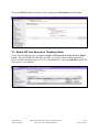
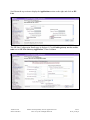
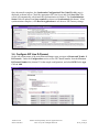
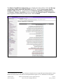
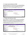
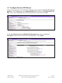
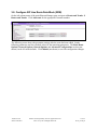
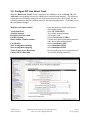
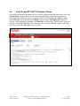
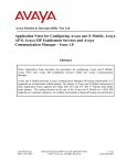
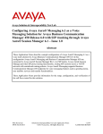
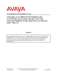
1
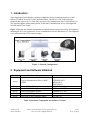
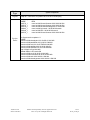
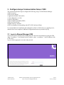
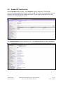
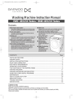
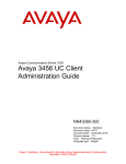
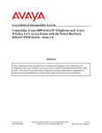
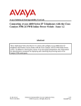
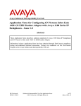
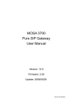
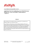
Avaya Solution & Interoperability Test Lab Application Notes for Avaya B179 SIP Conference Phone with Avaya Communication Server 1000 Release 6.0 – Issue 1.0 Abstract These Application Notes describe a solution comprised of Avaya Communication Server 1000 Release 6.0 and the Avaya B179 SIP Conference Phone. The B179 is a SIP VoIP conference Telephone that registers as a 3rd Party SIP Line client with Communication Server 1000 Release 6.0. The solution supports calling among the B179 and other Communication Server 1000supported non-SIP and SIP Line clients. Testing was conducted by the Avaya Solution and Interoperability Test Lab. TH; Reviewed: SPOC 07/08/2011 Solution & Interoperability Test Lab Application Notes ©2011 Avaya Inc. All Rights Reserved. 1 of 35 B179_CS1K_60 1. Introduction These Application Notes describe a solution comprised of Avaya Communication Server 1000 Release 6.0 and the Avaya B179 SIP Conference Phone. The B179 is a SIP VoIP conference telephone that registers as a 3rd Party SIP Line client with Communication Server 1000 Release 6.0. This solution supports calling among the B179 and other Communication Server 1000-supported non-SIP and SIP Line clients. Figure 1 illustrates the network configuration of equipment that was used for testing. All telephones, including the B179, are registered to Avaya Communication Server 1000 release 6.0. The telephones were configured in the 55xxx extension range. Figure 1: Network Configuration 2. Equipment and Software Validated Provider Hardware Component Avaya Avaya Communication Server 1000E CPPM Avaya Avaya Avaya Avaya Avaya Avaya 1140e IP Desk phone Avaya 2004 IP Desk phone Avaya IP Softphone 2050PC Avaya M3904 Digital Phone Avaya B179 SIP Conference Phone Software Version VERSION 4021 RELEASE 6 ISSUE 00 R + SIP: 04.01.13.00 UNIStim: 0622B76 UNIStim: 4.01.041 N/A 2.2 and 2.2.1 Table 1: Hardware Components and Software Versions TH; Reviewed: SPOC 07/08/2011 Solution & Interoperability Test Lab Application Notes ©2011 Avaya Inc. All Rights Reserved. 2 of 35 B179_CS1K_60 Update Type Deplist Update Components DepList 1: core Issue: 03 (created: 2011-04-26 15:23:48 (est)) In system patches: 6 NAME RPM p28774_1 nortel-cs1000-Jboss-Quantum-6.00.18.00-00.i386 p28797_1 nortel-cs1000-Jboss-Quantum-6.00.18.00-00.i386 p29703_1 nortel-cs1000-shared-ssSubagent-6.00.18-00.i386 p28961_1 nortel-cs1000-pi-control-1.00.00.00-00.noarch p30043_1 nortel-cs1000-OS-1.00.00.00-00.noarch p30274_1 nortel-cs1000-Jboss-Quantum-6.00.18.00-00.i386 Service Packs TH; Reviewed: SPOC 07/08/2011 In System service updates: 11 NAME nortel-cs1000-shared-pbx-6.00.18.065-01.i386.002 nortel-cs1000-patchWeb-6.00.18.65-01.i386.001 nortel-cs1000-vtrk-6.00.18.65-TMP410.i386.000 nortel-cs1000-dmWeb-6.00.18.62-00.i386.001 nortel-cs1000-ISECSH-6.00.18.62-00.i386.000 ntp-4.2.4p8-1.el5.pp.i386.000 tzdata-2009u-1.el5.noarch.000 nortel-cs1000-csv-6.00.18.65-04.i386.000 nortel-cs1000-linuxbase-6.00.18.65-06.i386.000 nortel-cs1000-auth-6.00.18.65-01.i386.000 nortel-cs1000-shared-general-6.00.18.62-01.i386.000 Solution & Interoperability Test Lab Application Notes ©2011 Avaya Inc. All Rights Reserved. 3 of 35 B179_CS1K_60 3. Configure Avaya Communication Server 1000 This section describes the steps to configure the following, using CS 1000 Element Manager: SIP Line service SIP Line D-Channel Application Module Link (AML) Value Added Server (VAS) Zone for SIP phones SIP Line Route Data Block (RDB) SIP Line Virtual Trunk Media Gateway Controller SIP Line telephone corresponding to the B179 SIP Conference Phone It is assumed that basic installation and configuration of the CS 1000 call server, signaling server, and node have been completed. Additional configuration details are provided in [1, 2]. 3.1. Log in to Element Manager (EM) Access the Unified Communications Management (UCM) web based interface by using the URL “http://<ip-address>” in an Internet browser window, where “<ip-address>” is the IP address of the UCM server. Log in with the appropriate user name and password. TH; Reviewed: SPOC 07/08/2011 Solution & Interoperability Test Lab Application Notes ©2011 Avaya Inc. All Rights Reserved. 4 of 35 B179_CS1K_60 The following Unified Communications Management screen will be displayed. Click on the Element Name corresponding to the Element Manager (EM). The CS 1000 Element Manager page appears as shown below. TH; Reviewed: SPOC 07/08/2011 Solution & Interoperability Test Lab Application Notes ©2011 Avaya Inc. All Rights Reserved. 5 of 35 B179_CS1K_60 3.2. Enable SIP Line Service Select Customers in the left pane. The Customers screen is displayed. Click the link associated with the appropriate customer, in this case 00. The system can support more than one customer with different network settings and options. In the sample configuration, only one customer was configured on the system. The Customer Details screen is displayed next. Select SIP Line Service to edit its parameters. TH; Reviewed: SPOC 07/08/2011 Solution & Interoperability Test Lab Application Notes ©2011 Avaya Inc. All Rights Reserved. 6 of 35 B179_CS1K_60 Check the SIP Line Service checkbox, enter an appropriate Root domain, and click Save. 3.3. Enable SIP Line Service on Telephony Node On the Element Manager page, navigate to System IP Network Nodes: Servers, Media Cards. Note the IP address of the SIP Line Node, as it will be used in configuring the B179 later. It would be displayed where X.X.X.X is indicated below. Select the Node ID on which SIP Line service is to be enabled. TH; Reviewed: SPOC 07/08/2011 Solution & Interoperability Test Lab Application Notes ©2011 Avaya Inc. All Rights Reserved. 7 of 35 B179_CS1K_60 Scroll down the top section to display the Applications section on the right, and click on SIP Line. The SIP Line Configuration Details page is displayed. Check Enable gateway service on this node next to SIP Line Gateway Application: Then click Save. TH; Reviewed: SPOC 07/08/2011 Solution & Interoperability Test Lab Application Notes ©2011 Avaya Inc. All Rights Reserved. 8 of 35 B179_CS1K_60 The Node Details screen then returns. Click the Save button on this screen. Select Transfer Now on the Node Saved page as shown below. TH; Reviewed: SPOC 07/08/2011 Solution & Interoperability Test Lab Application Notes ©2011 Avaya Inc. All Rights Reserved. 9 of 35 B179_CS1K_60 Once the transfer completes, the Synchronize Configuration Files (Node ID <id>) page is displayed as shown below. Check the appropriate SIP Line Server and click Start Sync. The screen will automatically refresh until the synchronization is finished. The Synchronization Status field will update from Sync required (as shown) to Synchronized (not shown). After synchronization completes, click Restart Applications to use the new SIP Gateway settings. 3.4. Configure SIP Line D-Channel On the left column menu of the main Element Manager page, navigate to Routes and Trunks D-Channels. Under the Configuration section, select a D-Channel number from the Choose a D-Channel Number list (channel 33 in the sample configuration), and select DCH for the type. Click to Add. TH; Reviewed: SPOC 07/08/2011 Solution & Interoperability Test Lab Application Notes ©2011 Avaya Inc. All Rights Reserved. 10 of 35 B179_CS1K_60 The D-Channels Property Configuration screens below show the parameter values after configuring the D-channel. DCIP is selected for D channel Card Type, Meridian Meridian1 (SL1) is selected for Interface type for D-channel, and an appropriate Designator is entered. The remaining parameters have their default values. Click the Basic options (BSCOPT) link to expand that section. Click Edit to configure Remote Capabilities. TH; Reviewed: SPOC 07/08/2011 Solution & Interoperability Test Lab Application Notes ©2011 Avaya Inc. All Rights Reserved. 11 of 35 B179_CS1K_60 The Remote Capabilities Configuration page is displayed as shown below. Select the Message waiting interworking with DMS-100 (MWI) check box,1 and the Network name display method 2 (ND2) check box. At the bottom of the Remote Capabilities Configuration page, click Return - Remote Capabilities (not shown), and the D-Channel Property Configuration page reappears as shown in the previous screen. Click on Submit . 1 Note that although the Avaya B179 SIP Conference Telephone does not support Message Waiting Indicator, this D channel can also be used for other SIP Line IP telephones that do support it, so it is enabled here for that purpose. TH; Reviewed: SPOC 07/08/2011 Solution & Interoperability Test Lab Application Notes ©2011 Avaya Inc. All Rights Reserved. 12 of 35 B179_CS1K_60 3.5. Configure Application Module Link (AML) On the left column menu of the main Element Manager page, navigate to System Interfaces Application Module Link, and click Add (not shown). The New Application Module Link page is displayed. Enter the AML port number in the Port number text box. The SIP Line Service can use ports 32 through 127. In the sample configuration, the SIP Line Service is configured to use port 32. Enter an appropriate Description. Click Save to save the configuration. 3.6. Configure Value Added Server (VAS) On the left column menu of the main Element Manager page, navigate to System Interfaces Value Added Server. Click Add and then click Ethernet LAN Link on the Add Value Added Server page that is displayed next (not shown). On the Ethernet Link page that is displayed next, enter a Value added server ID (32 in the sample configuration), and select the AML number created in the previous section for Ethernet LAN Link. Ensure that the Application Security check box is unchecked. Click Save (not shown). The screen below shows the result of adding the value added server. TH; Reviewed: SPOC 07/08/2011 Solution & Interoperability Test Lab Application Notes ©2011 Avaya Inc. All Rights Reserved. 13 of 35 B179_CS1K_60 3.7. Configure Zone for SIP Phones On the left column menu of the main Element Manager page, navigate to System IP Network Zones. On the Zones page, select Bandwidth Zones (not shown). On the Bandwidth Zones page, choose a new Bandwidth Zone from the drop-down box and click on to Add. On the Zone Basic Property and Bandwidth Management page, enter an appropriate Description. Defaults can be used for the remaining fields. Click Submit. TH; Reviewed: SPOC 07/08/2011 Solution & Interoperability Test Lab Application Notes ©2011 Avaya Inc. All Rights Reserved. 14 of 35 B179_CS1K_60 3.8. Configure SIP Line Route Data Block (RDB) On the left column menu of the main Element Manager page, navigate to Routes and Trunks Routes and Trunks. Click Add route for the appropriate customer number. The following screen shows the parameter settings after the route has been added. Set the following parameters and leave default values for the remaining parameters. The Basic Route Options, Network Options, General Options, and Advanced Configurations sections (not shown) can be left at the defaults. Click Submit (not shown) to save the configuration changes. TH; Reviewed: SPOC 07/08/2011 Solution & Interoperability Test Lab Application Notes ©2011 Avaya Inc. All Rights Reserved. 15 of 35 B179_CS1K_60 Route number (ROUT) Designator field for trunk (DES) Trunk type (TKTP) Incoming and outgoing trunk (ICOG) Access code for the trunk route (ACOD) The route is for a virtual trunk route (VTRK) Zone for codec selection and bandwidth management (ZONE) Node ID of signaling server of this route (NODE) Protocol ID for the route (PCID) Integrated services digital network option (ISDN) Mode of operation (MODE) D channel number (DCH) Interface type for route (IFC) Network calling name allowed (NCNA) Select the route number Enter an appropriate name Select TIE trunk data block (TIE) Select Incoming and Outgoing (IAO) Enter the access code Check the box Enter a zone2 Enter the node ID of the SIP Line Gateway Select SIP Line (SIPL) Check the box Select Route uses ISDN Signaling Link (ISLD) Enter the D-channel number Select Meridian M1 (SL1) Check the box 2 Note that this must be a zone of type VTRK and must be different than the zone created for the SIP phones in Section 3.7. In the sample configuration, the VTRK zone was 254. TH; Reviewed: SPOC 07/08/2011 Solution & Interoperability Test Lab Application Notes ©2011 Avaya Inc. All Rights Reserved. 16 of 35 B179_CS1K_60 3.9. Configure SIP Line Virtual Trunk When the Routes and Trunks screen is displayed after adding the route in Section 3.8, click Add trunk corresponding to the newly added route to add new trunk members. The following screen shows the parameter settings for one of the trunks after they have been added. Set the following parameters and leave default values for the remaining parameters. Click Save to save the configuration changes. Multiple trunk input number Trunk data block Terminal Number Designator field for trunk Extended Trunk Route number, Member number Card Density Start arrangement Incoming Start arrangement Outgoing Trunk Group Access Restriction Channel ID for this trunk TH; Reviewed: SPOC 07/08/2011 Enter the number of trunks (only shown when adding trunks) Select IP Trunk (IPTI) An available terminal number. A descriptive text. Select Virtual trunk (VTRK) Current route number and starting member. (only shown when adding trunks) Select Octal Density (8D) Select Immediate (IMM) Select Immediate (IMM) Desired trunk group access restriction level. An available starting channel ID. Solution & Interoperability Test Lab Application Notes ©2011 Avaya Inc. All Rights Reserved. 17 of 35 B179_CS1K_60 3.10. Configure Media Gateway Controller This section describes configuration of the G.729 audio codec for the Media Gateway Controller (MGC) to support calls between the B179 and non-IP telephones. On the left column menu of the main Element Manager page, navigate to IP Network Media Gateways. Click on the IPMG that supports the digital and analog phones in the system. On the IPMG Property Configuration screen, click Next (not Shown). Expand the VGW and IP phone codec profile section. In that section, check the Select checkbox next to and expand the Codec G729A section. TH; Reviewed: SPOC 07/08/2011 Solution & Interoperability Test Lab Application Notes ©2011 Avaya Inc. All Rights Reserved. 18 of 35 B179_CS1K_60 If Annex B support is desired as in the sample configuration, check the VAD checkbox. Note that the VAD setting should be consistent with the VAD setting in the B179 configuration. Click Save. Click on OK to save the configuration. TH; Reviewed: SPOC 07/08/2011 Solution & Interoperability Test Lab Application Notes ©2011 Avaya Inc. All Rights Reserved. 19 of 35 B179_CS1K_60 When the Media Gateway screen returns, select the radio button for the IPMG and click Reboot. 3.11. Configure SIP Line Telephone This section describes the screens for configuring a SIP Line telephone to support the Avaya B179 SIP Conference Telephone. On the left column menu of the main Element Manager page, navigate to Phones. On the Search For Phones page, click Add…. TH; Reviewed: SPOC 07/08/2011 Solution & Interoperability Test Lab Application Notes ©2011 Avaya Inc. All Rights Reserved. 20 of 35 B179_CS1K_60 On the New Phones page, select the Customer, select the Phone Type radio button, and then select UEXT-SIPL – Universal Extension SIPL. Click Preview. TH; Reviewed: SPOC 07/08/2011 Solution & Interoperability Test Lab Application Notes ©2011 Avaya Inc. All Rights Reserved. 21 of 35 B179_CS1K_60 The following screens show the parameter values after the phone has been added. In the General Properties section, fill in the following fields, and leave the remaining fields at their default values: Customer Number Terminal Number Designation Zone SIP User Name Node Id Optional Features: Max Client Count SIPN SIP3 TH; Reviewed: SPOC 07/08/2011 Select the customer number Enter a free TN number Enter a reference name Enter the zone from Section 3.7 The phone extension number used to log in at the phone The ID of this node Select the check box Set to 0 Set to 1 Solution & Interoperability Test Lab Application Notes ©2011 Avaya Inc. All Rights Reserved. 22 of 35 B179_CS1K_60 In the Features section, fill in the following fields, leaving the remaining fields at their defaults. Call Party Name Display (CNDA) Call Number Information (CNIA) Restricted Conference or Transfer (FTTC)) Media Security Encryption (MSEC) Station Control Password (SCPW) Trunk Group Access Restriction (TGAR) Instrument Type (TYPE) Universal Extension User (UTXY) Allowed Allowed Unrestricted Conf. or Transfer Media Security Never (MSNV) Enter password used to log in at the phone Set appropriately UEXT SIPL In the Keys section, fill in the following: Key No. 0 Directory Number Multiple Appearance Redirection Prime (MARP) First Name Last Name Key No. 1 UADN SCR – Single Call Ringing Phone extension number Select the Checkbox Enter a name Enter a name HOT_U – Hotline(Universal) The phone extension prefixed by the UADN Prefix3 Click Save (not shown) to save the configuration for this phone. 3 The UADN is used to make and receive calls between the SIP Line Gateway and the Universal Extensions. However, this key is used only by the SIP Line Gateway (SLG) application. The UADN is not dialed by end users. It is only used internally between the Call Server and the SIP Line Gateway application. See Section 3.2. TH; Reviewed: SPOC 07/08/2011 Solution & Interoperability Test Lab Application Notes ©2011 Avaya Inc. All Rights Reserved. 23 of 35 B179_CS1K_60 4. Configure Avaya B179 IP Conference Phone This section describes how to access the B179 web interface and configure the phone to register to Avaya Communication Server 1000. It assumes that the telephone has been administered an IP address either through DCHP or static configuration. Additional configuration details are provided in [3]. 4.1. SIP Registration In the web browser address field, enter the B179 IP address. The login page will appear as shown below. Enter admin for the user name and the appropriate password. Click Login, and the main configuration screen appears as shown on the next page, where Settings Network has been selected and shows the DHCP network configuration that was configured on the B179 in the sample configuration. TH; Reviewed: SPOC 07/08/2011 Solution & Interoperability Test Lab Application Notes ©2011 Avaya Inc. All Rights Reserved. 24 of 35 B179_CS1K_60 TH; Reviewed: SPOC 07/08/2011 Solution & Interoperability Test Lab Application Notes ©2011 Avaya Inc. All Rights Reserved. 25 of 35 B179_CS1K_60 4.2. Configure SIP Signalling Settings To configure the SIP signalling settings, navigate to Settings SIP, and fill in the following: Under Account 1: Enable account Account name User Realm Registrar and Proxy Authentication name Password Registration interval Select the Yes radio button Meaningful name for account status display on phone screen Extension (SIP User Name) of the SIP Line telephone configured in Section 3.11 Use the default of “*” SIP domain configured in the CS 1000, with Port number Extension (SIP User Name) of the SIP Line telephone configured in Section 3.11 The Station Control Password of the SIP Line telephone configured in Section 3.11 Enter a value (300 was used in the sample configuration) Under Advanced: Enable blind transfer Outbound proxy Select the No radio button4 No input was used in this configuration Under Transport: Protocol Local Port Select the TCP or UDP radio button (UDP shown) Enter 5070 Click Save. The SIP configuration screen is shown on the next page. 4 This feature is not yet supported in this configuration TH; Reviewed: SPOC 07/08/2011 Solution & Interoperability Test Lab Application Notes ©2011 Avaya Inc. All Rights Reserved. 26 of 35 B179_CS1K_60 TH; Reviewed: SPOC 07/08/2011 Solution & Interoperability Test Lab Application Notes ©2011 Avaya Inc. All Rights Reserved. 27 of 35 B179_CS1K_60 4.3. Media Configuration To configure the audio codec settings, navigate to Settings Media, and select the priority for codec selection. CS1000 6.0 does not support the G7.22 Codec, so this selection should be set to 0 – Disabled. Because there were some interoperability issues with G.729 it is recommended that this option should also be set to 0 – Disabled. Set the G711 Ulaw codec to 4 – High. Defaults can be used for the remaining fields. Click on Save when done. ______________________________________________________________________________ TH; Reviewed: SPOC 07/08/2011 Solution & Interoperability Test Lab Application Notes ©2011 Avaya Inc. All Rights Reserved. 28 of 35 B179_CS1K_60 After the configuration has been saved, the B179 will register with the CS 1000, and a display similar to those shown in the figures below will appear on the telephone. The Hostname is displayed at the center, and in the lower left corner is the Account name. To the left of the Account name is a square icon that indicates the SIP registration status of the B179. If the square is filled in as shown below, the B179 has successfully registered. If the square is not filled in, registration was unsuccessful. TH; Reviewed: SPOC 07/08/2011 Solution & Interoperability Test Lab Application Notes ©2011 Avaya Inc. All Rights Reserved. 29 of 35 B179_CS1K_60 5. Observations During testing with this configuration the following observations were made: Calls from the B179 via the inbound call log are not supported. Group conference by the B179 is not supported. The use of the G.729audio codec is not recommended because of possible interoperability issues. It is recommended to disable Blind Transfer as indicated in section 4.2 because of possible interoperability issues. 6. Verification Steps This section provides tests that can be performed to verify proper configuration of the CS 1000 and B179. 6.1. Verify Avaya Communication Server 1000 6.1.1. Verify D-Channel Status Verify status of the SIP Line D-Channels by navigating to System Maintenance, selecting Select by Overlay, LD 96 – D-Channel, and D-Channel Diagnostics. The screen below shows the APPL_STATUS of the SIP Line D-Channel as “OPER” and the LINK_STATUS as “EST ACTV”. This is normal. TH; Reviewed: SPOC 07/08/2011 Solution & Interoperability Test Lab Application Notes ©2011 Avaya Inc. All Rights Reserved. 30 of 35 B179_CS1K_60 6.1.2. Verify SIP Registration Status In the Element Manager Web interface, navigate to System IP Network Maintenance and Reports on the left pane. If there are multiple Nodes, select the node of the SIP Line. Click GEN CMD. The General Commands page is displayed. From the Group drop-down menu select SipLine, from the Command drop-down menu select slgSetShowByUID, enter the B179 extension in UserID, and click on RUN. The output shown indicates successful registration and displays details of the registration parameters. Note that if the B179 has not registered, the error message “Invalid userId 55575” will be returned instead of the detailed registration information. TH; Reviewed: SPOC 07/08/2011 Solution & Interoperability Test Lab Application Notes ©2011 Avaya Inc. All Rights Reserved. 31 of 35 B179_CS1K_60 TH; Reviewed: SPOC 07/08/2011 Solution & Interoperability Test Lab Application Notes ©2011 Avaya Inc. All Rights Reserved. 32 of 35 B179_CS1K_60 6.2. Verify Avaya B179 SIP Conference Phone Successful registration of the phone can be verified by inspecting the status icon to the left of the Account name, shown at the lower left of the telephone display as described in Section 4.3. Registration and call tracing can be performed on the B179 by navigating to Status Log. Select SIP Trace on the left and click Change. Ensure that the SIP logging radio button is selected. After attempting registration, click Refresh to see the result. The log can be cleared at any time by clicking Clear Log. The screen below shows the REGISTER message sent by the B179 for a successful registration to the CS 1000. TH; Reviewed: SPOC 07/08/2011 Solution & Interoperability Test Lab Application Notes ©2011 Avaya Inc. All Rights Reserved. 33 of 35 B179_CS1K_60 7. Conclusion As illustrated in these Application Notes, Avaya Communication Server 1000 Release 6.0 and the Avaya B179 SIP Conference Phone can be used together in an integrated solution. 8. Additional References Product documentation for Avaya products may be found at http://support.avaya.com. [1] Communication Server 1000 - Element Manager System Reference – Administration, Release: 6.0, Document Revision: 03.20, Document #NN43001-632. [2] Communication Server 1000 SIP Line Fundamentals, Release 6.0, Document #NN43001-508, 01.08, 9 February 2010. [3] Avaya B179 SIP Conference Phone Installation and Administration Guide TH; Reviewed: SPOC 07/08/2011 Solution & Interoperability Test Lab Application Notes ©2011 Avaya Inc. All Rights Reserved. 34 of 35 B179_CS1K_60 ©2011 Avaya Inc. All Rights Reserved. Avaya and the Avaya Logo are trademarks of Avaya Inc. All trademarks identified by ® and ™ are registered trademarks or trademarks, respectively, of Avaya Inc. All other trademarks are the property of their respective owners. The information provided in these Application Notes is subject to change without notice. The configurations, technical data, and recommendations provided in these Application Notes are believed to be accurate and dependable, but are presented without express or implied warranty. Users are responsible for their application of any products specified in these Application Notes. Please e-mail any questions or comments pertaining to these Application Notes along with the full title name and filename, located in the lower right corner, directly to the Avaya Solution & Interoperability Test Lab at [email protected] TH; Reviewed: SPOC 07/08/2011 Solution & Interoperability Test Lab Application Notes ©2011 Avaya Inc. All Rights Reserved. 35 of 35 B179_CS1K_60