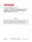
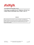
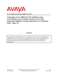
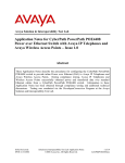
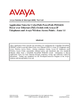
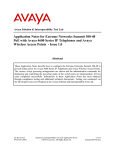
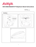
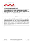
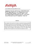
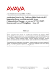
1
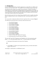
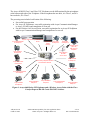
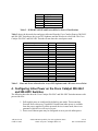
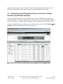
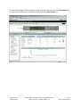
Avaya Solution & Interoperability Test Lab
Using Cisco Catalyst Express 500-24LC Switch and 50024PC Switch with an IEEE 802.3af Compliant Power over
Ethernet card for Avaya 4600 and 5600 Series IP Telephones
and Avaya Wireless Access Points - Issue 1.0
Abstract
These Application Notes describe how to configure the Cisco Catalyst Express 500-24LC
switch and 500-24PC switch to provide inline power for Avaya 4600 and 5600 Series IP
Telephones and Avaya Wireless Access Points. The various powering arrangements and the
administration commands for displaying and controlling the powering status of the switch
ports are covered.
AK; Reviewed:
GAK 2/3/2006
Solution & Interoperability Test Lab Application Notes
©2006 Avaya Inc. All Rights Reserved.
1 of 10
PoE-CiscoXP500.doc
1. Introduction
Power over Ethernet (PoE) allows a switch to supply power to a network device within the same
cable that carries the Ethernet traffic. This simplifies network installation and powering design,
removing the need for separate power supplies for network devices. IEEE 802.3af defines a
standard protocol to be used by power sourcing equipment (PSE) and powered devices (PD). The
Cisco Catalyst Express 500-24LC and 500-24PC Switches are IEEE 802.3af compliant PSEs and
can provide inline power to the Avaya 4600 and 5600 series IP Telephones and Avaya Wireless
Access Points, which are IEEE 802.3af compliant PDs.
Only the first four ports of the Cisco Catalyst Express 500-24LC switch are capable of providing
Power over Ethernet. However, the Cisco Express 500-24PC is able to provide PoE for all 24
ports.
The Avaya product configurations addressed by these Application Notes are shown in Figure 1.
The following Avaya Powered Devices are directly connected to the switch:
•
•
•
•
•
•
•
•
•
•
•
•
•
•
Avaya 4601 IP Telephone
Avaya 4602 IP Telephone
Avaya 4602SW IP Telephone
Avaya 4610SW IP Telephone
Avaya 4620 IP Telephone
Avaya 4620SW IP Telephone
Avaya 4621SW IP Telephone
Avaya 4622SW IP Telephone
Avaya 4625SW IP Telephone
Avaya 5601 IP Telephone
Avaya 5602SW IP Telephone
Avaya 5610SW IP Telephone
Avaya Gen-2 4606, 4612, and 4624 IP Telephones
Avaya Wireless AP-4/5/6 802.11a/b/g Access Point
The Avaya 4612 and 4624 IP Telephones can be identified as Gen-2 by inspecting the model
number. “2A” in the model number indicates Gen-2. The model number can be found by:
•
Inspecting the label attached to the bottom of the Telephone.
OR
•
Pressing Mute, V, I, E, W, # on the keypad and then pressing * until the model number
appears. Press # to exit.
An example of a model number is 4612D02A-003 (Gen-2).
AK; Reviewed:
GAK 2/3/2006
Solution & Interoperability Test Lab Application Notes
©2006 Avaya Inc. All Rights Reserved.
2 of 10
PoE-CiscoXP500.doc
The Avaya 4620SW Class 2 and Class 3 IP Telephones can be differentiated by the microphone
at the bottom right side of the Telephone. If the microphone has one hole, it is Class 2, and if it
has two holes, it is Class 3.
The powering tests included verification of the following:
• Successful boot operation
• For Avaya IP Telephones, successful registration with Avaya Communication Manager
or Avaya IP Office and completion of a test call.
• For the Wireless LAN Access Point, successful registration for an Avaya IP Softphone
with Avaya Communication Manager and completion of a test call.
Avaya IP Office 403
Avaya 4602/4602SW
IP Telephone
Avaya S8700 Media
Server
Avaya G650 Avaya 4601
IP Telephone
Media
Gateway
Avaya 4610SW
IP Telephone
Avaya Gen-2 4606
IP Telephone
Avaya 5601
IP Telephone
Wireless Laptop
(802.11b)
With Avaya IP
Softphone
Avaya Wireless
AP-4/5/6
Access Point
Cisco Catalyst Express 500-24LC
and 500-24PC Switches
Avaya 5610SW
IP Telephone
Avaya Gen-2 4612/4624
IP Telephone
Avaya 4625SW
IP Telephone
Avaya 5620SW
IP Telephone
Avaya 4621SW IP
Telephone
Avaya 4622SW IP
Telephone
Avaya 4620/4620SW
IP Telephone
Avaya 5602SW IP
Telephone
Figure 1: Avaya 4600 Series IP Telephones and a Wireless Access Point with the Cisco
Catalyst Express 500-24LC and 500-24PC Switches.
AK; Reviewed:
GAK 2/3/2006
Solution & Interoperability Test Lab Application Notes
©2006 Avaya Inc. All Rights Reserved.
3 of 10
PoE-CiscoXP500.doc
2. Equipment and Software Validated
The following equipment and software were used for the sample configuration provided:
Network Component
Avaya 4601 IP Telephone
Avaya 4602/4602SW IP Telephone
Avaya 4606 IP Telephone
Avaya 4610SW IP Telephone
Avaya 4612/4624 Gen-2 IP Telephone
Avaya 4620/4620SW IP Telephone
Avaya 4621SW IP Telephone
Avaya 4622SW IP Telephone
Avaya 4625SW IP Telephone
Avaya 5601 IP Telephone
Avaya 5602SW IP Telephone
Avaya 5610SW IP Telephone
Avaya 5620SW IP Telephone
Avaya IP Softphone
Avaya AP-4/5/6
Avaya IP Office 403
Avaya Communication Manager (Avaya S8700
Media Server)
Cisco Catalyst Express 500-24LC and 500-24PC
IOS Software
Software Version
1.8.2
1.8.2
1.8.3
2.3
1.8.3
2.3
2.3
2.3
2.5
1.8.6
1.8.6
2.1
2.1
5.1.4.6
2.4.5
3.0
3.0
12.2(25)FY
Table 1 – Network Component Software Versions
3. IEEE 802.3af PoE Implementation on the Avaya PDs and
Cisco Catalyst Express 500-24LC and 500-24PC Switches
In June 2003, the IEEE approved a standard for Power over Ethernet. The maximum power is
15.4W per PSE port and the maximum power delivered to a powered device, accounting for
cable loss, is 12.95W. Optionally, powered devices may also be classified based on the
maximum power the device will draw. The Cisco Catalyst Express 500-24LC, 500-24PC, and
Avaya PDs support this optional classification. The Cisco Catalyst Express 500-24LC and 50024PC Switches can detect the Avaya PDs with the correct classification and deliver the
appropriate power.
The IEEE 802.3af classifications are given in Table 2. Class 0 is a legacy class for devices built
before the standard evolved to power classification levels.
AK; Reviewed:
GAK 2/3/2006
Solution & Interoperability Test Lab Application Notes
©2006 Avaya Inc. All Rights Reserved.
4 of 10
PoE-CiscoXP500.doc
Class
PSE Output Max. Power
0
1
2
3
4
15.4W
4.0W
7.0W
15.4W
Treat as Class 0
Table 2 – IEEE 802.3af PSE and Powered-Device Power Classifications
Table 3 shows the detected class and power allocated from the Cisco Catalyst Express 500-24LC
and 500-24PC Switches to the Avaya IP Telephones and the Wireless Access Point. The Cisco
Catalyst 500-24LC and 500-24PC Switches do not show the actual power used.
Avaya IP Telephones
4601
4602
4602SW
4610SW
4620
4620SW (Pre 11/2004)
4620SW (Post 11/2004)
4621SW
4622SW
4625SW
5601
5602SW
5610SW
5620SW
Gen-2 4606
Gen-2 4612
Gen-2 4624
Avaya AP-4/5/6
Class
2
1
2
2
3
3
2
2
2
3
2
1
2
2
0
0
0
0
Power Allocated (Watts)
7
4
7
7
15.4
15.4
7
7
7
15.4
7
4
7
7
15.4
15.4
15.4
15.4
Table 3 – Class and Power Allocation for Avaya IP Telephones and a Wireless Access Point
4. Configuring Inline Power on the Cisco Catalyst 500-24LC
and 500-24PC Switches
The following describes how the Cisco Catalyst 500-24LC and 500-24PC Switches interact with
powered devices.
1. PoE-capable ports are configured by default to auto mode. This means that
Powered Device discovery is enabled. If insufficient inline power is available
from the power supplies for all the powered devices in auto mode, there is no
guarantee which device will receive power.
2. Power over Ethernet ports may be configured to never provide inline power.
AK; Reviewed:
GAK 2/3/2006
Solution & Interoperability Test Lab Application Notes
©2006 Avaya Inc. All Rights Reserved.
5 of 10
PoE-CiscoXP500.doc
The ports connected to the Avaya 4600 and 5600 IP Telephones and Avaya Wireless Access
Points must use the default auto mode in order to be powered by the Cisco switches.
4.1. Configuring and Verifying Inline Power on the Cisco Catalyst
500-24LC and 500-24PC Switches
The Cisco Catalyst Express 500-24LC and 500-24PC Switches can both be accessed using a
web-based interface. Launch an Internet browser and type the switch’s IP address in the address
field. The following screenshots are taken from the Cisco Catalyst Express 500-24PC Switch.
To enable or disable PoE on a certain port of the switch, the user can select the ConfigureÆPort
Settings and then, under PoE column, select auto or never.
AK; Reviewed:
GAK 2/3/2006
Solution & Interoperability Test Lab Application Notes
©2006 Avaya Inc. All Rights Reserved.
6 of 10
PoE-CiscoXP500.doc
To view the percentage of power being used up by the PDs, the user can access Dashboard and
view how much of the power is being allocated under the Switch Health area.
AK; Reviewed:
GAK 2/3/2006
Solution & Interoperability Test Lab Application Notes
©2006 Avaya Inc. All Rights Reserved.
7 of 10
PoE-CiscoXP500.doc
To view the information on a certain port on the switch, the user can move the mouse over to the
corresponding port in the picture and view the status, speed, duplex, and PoE of the port.
AK; Reviewed:
GAK 2/3/2006
Solution & Interoperability Test Lab Application Notes
©2006 Avaya Inc. All Rights Reserved.
8 of 10
PoE-CiscoXP500.doc
5. Verification Steps
•
•
•
•
Connect Avaya IP Telephones to Cisco Catalyst 500-24LC and 500-24PC Switches.
Verify that the Avaya IP Telephones can be powered properly.
Verify that the Avaya IP Telephones can register with Avaya Communication Manager
and IP Office and calls can be made successfully.
Use the web-based interface on the Cisco switch to check the power status.
Reset the switch. Verify that all the IP Telephones can be powered up properly.
6. Conclusion
The Cisco Catalyst 500-24LC and 500-24PC Switches can both provide inline power to the
Avaya 4600 and 5600 series IP Telephones and the Avaya AP 4/5/6 Wireless Access Point.
AK; Reviewed:
GAK 2/3/2006
Solution & Interoperability Test Lab Application Notes
©2006 Avaya Inc. All Rights Reserved.
9 of 10
PoE-CiscoXP500.doc
©2006 Avaya Inc. All Rights Reserved.
Avaya and the Avaya Logo are trademarks of Avaya Inc. All trademarks identified by ® and ™
are registered trademarks or trademarks, respectively, of Avaya Inc. All other trademarks are the
property of their respective owners. The information provided in these Application Notes is
subject to change without notice. The configurations, technical data, and recommendations
provided in these Application Notes are believed to be accurate and dependable, but are
presented without express or implied warranty. Users are responsible for their application of any
products specified in these Application Notes.
Please e-mail any questions or comments pertaining to these Application Notes along with the
full title name and filename, located in the lower right corner, directly to the Avaya Solution &
Interoperability Test Lab at [email protected]
AK; Reviewed:
GAK 2/3/2006
Solution & Interoperability Test Lab Application Notes
©2006 Avaya Inc. All Rights Reserved.
10 of 10
PoE-CiscoXP500.doc