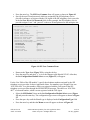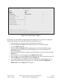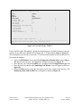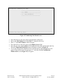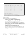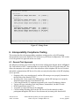
1
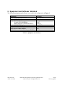
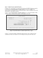
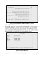
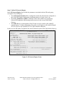
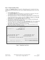
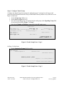
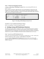
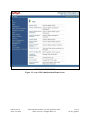
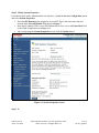
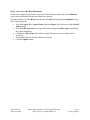
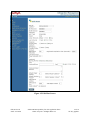
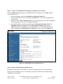
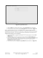
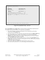
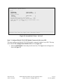
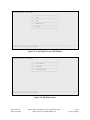
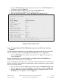
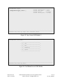
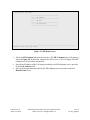
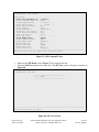
Avaya Solution & Interoperability Test Lab
Application Notes for the Hitachi Communication
Technologies NT-SG with Avaya SIP Enablement Services
and Avaya Communication Manager - Issue 1.0
Abstract
These Application Notes describe the configuration of the Hitachi Communication
Technologies NT-SG with an Avaya IP Telephony solution consisting of Avaya
Communication Manager, Avaya SIP Enablement Services, Avaya 4600 Series H.323
Telephones, Avaya SP-1020A SIP Telephone, and Avaya one-X™ Desktop Edition. The
Hitachi Communication Technologies NT-SG is a session border controller that integrates
signaling and media control for SIP. Information in these Application Notes has been obtained
through compliance testing and additional technical discussions. Testing was conducted via
the DeveloperConnection Program at the Avaya Solution and Interoperability Test Lab.
KN; Reviewed:
SPOC 9/21/2006
Solution & Interoperability Test Lab Application Notes
©2006 Avaya Inc. All Rights Reserved.
1 of 52
NT-SG_AppNote
1. Introduction
These Application Notes describe the configuration of the Hitachi Communication Technologies
NT-SG in an Avaya IP Telephony environment consisting of an Avaya SIP Enablement Services,
Avaya Communication Manager, Avaya 4600 Series H.323 Telephones, Avaya SP-1020A SIP
Telephone, and Avaya one-X™ Desktop Edition.
The Hitachi Communication Technologies NT-SG is a session border controller that integrates
signaling and media control for SIP. It resides at the enterprise’s network border and serves as
both the source and destination for all SIP signaling messages and media streams entering or
exiting the enterprise’s network.
Figure 1 illustrates the configuration that was used to verify the interoperability the Hitachi
Telecommunication Technologies NT-SG with an Avaya IP Telephony solution using SIP
trunking. The Avaya IP telephony solution located on the customer enterprise site contained:
•
Avaya S8400 Media Server installed into an Avaya G600 Media Gateway. The S8400
served as the host processor for Avaya Communication Manager.
•
Avaya SIP Enablement Services software operating on an Avaya S8500B server platform.
•
Avaya 4600 series IP telephone (configured to use the H.323 protocol).
•
Avaya SP-1020A SIP telephone.
•
Avaya one-X™ Desktop Edition SIP Softphone.
The SIP Service Provider Network consists of the following SIP components:
•
SIP Proxy server
•
SIP Registrar server
•
SIP redirect server
•
Phone Numbers
In the configuration shown in Figure 1, one network interface on the Hitachi Communication
Technologies NT-SG in the customer enterprise site was connected to the customer enterprise
site and the other network interface was connected to the SIP Service Provider network. Two SIP
trunks were configured between the Avaya Communication Manager and the Avaya SIP
Enablement Services. One SIP trunk was used for the sessions through the Hitachi
Communication Technologies NT-SG and the other was used for the sessions from/to the Avaya
SP-1020A SIP Telephone and the Avaya one-X™ Desktop Edition. The Avaya SIP Enablement
Services recognized the Avaya Communication Manager as a media server, and the Hitachi
Communication Technologies NT-SG as a trusted host. The Hitachi Communication
Technologies NT-SG terminated the SIP signaling messages and media streams between the
customer enterprise site and the SIP Service Provider network.
KN; Reviewed:
SPOC 9/21/2006
Solution & Interoperability Test Lab Application Notes
©2006 Avaya Inc. All Rights Reserved.
2 of 52
NT-SG_AppNote
Telephone numbers are assigned by the SIP telephony service provider. In these Application
Notes, two numbers were assigned. One was “050-3380-4036” as a pilot number, which was
registered with the Call Agent of the SIP telephony service provider through the SIP REGISTER
message. The other was “050-3380-4037” as a branch number, which was not registered with the
Call Agent
The administration of the network infrastructure shown in Figure 1 is not the focus of these
Application notes and will not be described. For administration of the network infrastructure
shown in Figure 1 refer to the appropriate documentation listed in Section 10.
Figure 1: Network Configuration Diagram
KN; Reviewed:
SPOC 9/21/2006
Solution & Interoperability Test Lab Application Notes
©2006 Avaya Inc. All Rights Reserved.
3 of 52
NT-SG_AppNote
2. Equipment and Software Validated
The following equipments and software were used for the configuration in Figure 1.
Equipment
Avaya SIP Enablement Services
Avaya S8400 Media Server
Avaya G600 Media Gateway
C-LAN (TN799DP HW0)
Media Processor (TN2302AP HW12)
Avaya 4620SW IP Telephone
Avaya SP-1020A SIP Telephone
Avaya one-X Desktop Edition
Hitachi Communication Technologies NT-SG
Software
3.1, load 18.0
3.1.1, load 628.7
FW17
FW110
2.4 (H.323)
2.02.01
R2.1
11-01
Table 1: Equipment and Software
KN; Reviewed:
SPOC 9/21/2006
Solution & Interoperability Test Lab Application Notes
©2006 Avaya Inc. All Rights Reserved.
4 of 52
NT-SG_AppNote
3. Configure Avaya Communication Manager
This section describes the steps for configuring a SIP trunk on Avaya Communication Manager.
The SIP trunk is established between Avaya Communication Manager and Avaya SIP
Enablement Services (SES) server. This trunk will carry the SIP signaling and RTP voice
packets sent to the Hitachi NT-SG.
The SIP trunk also provides the trunking necessary for SIP endpoint devices such as Avaya SP1020A SIP telephone and Avaya one-X Desktop Edition to use Avaya Communication Manager
in the recommended OPS configuration. It is not necessary to have SIP endpoints in order to use
SIP trunking to the Hitachi NT-SG. Thus the steps for SIP endpoints administration are omitted
in these Application Notes.
SIP signaling messages for all incoming calls from the SIP Service Provider Network to the
enterprise network are terminated at the Hitachi NT-SG, which forwards them to the Avaya SES
and are routed to Avaya Communication Manager via the SIP trunk. All outgoing calls to the SIP
Service Provider network via the Hitachi NT-SG are routed through Avaya Communication
Manager in order to use features such as automatic route selection and class of service
restrictions. Avaya Communication Manager creates the outbound SIP signaling that is routed
via Avaya SES to the Hitachi NT-SG.
The following configuration was performed via the System Access Terminal (SAT).
The steps shown in this section were configured on the Avaya S8400 media Server at the
enterprise site.
KN; Reviewed:
SPOC 9/21/2006
Solution & Interoperability Test Lab Application Notes
©2006 Avaya Inc. All Rights Reserved.
5 of 52
NT-SG_AppNote
Step 1 Confirm Necessary Optional Features
Using the SAT, verify that there exist sufficient SIP Trunks and Off-PBX Telephones capacities
by displaying the System-Parameters Customer-Options from shown in Figure 2. If a
required feature is not enabled or there is insufficient capacity, contact an authorized Avaya sales
representative to add additional capacity.
On Page 1 of the System-Parameters Customer-Options form, verify that the number of OPS
stations available is sufficient for the number of SIP telephones to be used.
display system-parameters customer-options
OPTIONAL FEATURES
G3 Version: V13
Location: 2
Platform: 20
Page
1 of
11
RFA System ID (SID): 1
RFA Module ID (MID): 1
Platform Maximum Ports:
Maximum Stations:
Maximum XMOBILE Stations:
Maximum Off-PBX Telephones - EC500:
Maximum Off-PBX Telephones OPS:
Maximum Off-PBX Telephones - SCCAN:
1300
900
100
20
20
0
USED
170
53
5
1
6
0
(NOTE: You must logoff & login to effect the permission changes.)
Figure 2: System-Parameters Customer-Options Form – Page 1
On Page 2, verify that the number of SIP trunks supported by the system is sufficient for the
combination of trunks to the Hitachi NT-SG, SIP endpoints and any other SIP trunks used.
KN; Reviewed:
SPOC 9/21/2006
Solution & Interoperability Test Lab Application Notes
©2006 Avaya Inc. All Rights Reserved.
6 of 52
NT-SG_AppNote
display system-parameters customer-options
OPTIONAL FEATURES
Page
IP PORT CAPACITIES
Maximum Administered H.323 Trunks:
Maximum Concurrently Registered IP Stations:
Maximum Administered Remote Office Trunks:
Maximum Concurrently Registered Remote Office Stations:
Maximum Concurrently Registered IP eCons:
Max Concur Registered Unauthenticated H.323 Stations:
Maximum Video Capable H.323 Stations:
Maximum Video Capable IP Softphones:
Maximum Administered SIP Trunks:
Maximum Number of DS1 Boards with Echo Cancellation:
Maximum TN2501 VAL Boards:
Maximum G250/G350/G700 VAL Sources:
Maximum TN2602 Boards with 80 VoIP Channels:
Maximum TN2602 Boards with 320 VoIP Channels:
Maximum Number of Expanded Meet-me Conference Ports:
100
100
400
900
0
10
40
40
400
USED
22
1
0
0
0
0
0
6
64
1
2
0
0
0
0
1
0
0
0
0
0
2 of
11
(NOTE: You must logoff & login to effect the permission changes.)
Figure 3: System-Parameters Customer-Options Form – Page 2
Step 2 Assign Node Names
In the IP Node Names form, assign the node name and IP address for Avaya SIP Enablement
Services at the enterprise site. In this case “SES-01” and “192.168.135.201” are being used,
respectively. The SES node name will be used throughout the other configuration screen of
Avaya Communication Manager. In this example “procr” and “192.168.135.140” are the name
and IP address assigned to the S8400 Media Server, and “shib-cln1” and “192.168.135.141” are
the name and IP address assigned to the C-LAN in the G600 Media Gateway.
change node-names ip
Page
1 of
1
IP NODE NAMES
Name
IP Address
Name
IP Address
SES-01
192.168.135.201
.
.
.
Shib-prw1
192.168.135.142
.
.
.
default
0 .0 .0 .0
.
.
.
ia770
192.168.135.147
.
.
.
nagasaki
192.168.131.170
.
.
.
procr
192.168.135.140
.
.
.
shib-cln1
192.168.135.141
.
.
.
shib-val1
192.168.135.144
.
.
.
.
.
.
.
.
.
.
.
.
.
.
.
.
.
.
.
.
.
.
.
.
.
.
.
.
.
.
.
.
.
.
.
.
.
.
.
.
.
.
.
.
.
.
.
.
.
.
.
( 8 of 8
administered node-names were displayed )
Use 'list node-names' command to see all the administered node-names
Use 'change node-names ip xxx' to change a node-name 'xxx' or add a node-name
Figure 4: IP Nodes Name Form
KN; Reviewed:
SPOC 9/21/2006
Solution & Interoperability Test Lab Application Notes
©2006 Avaya Inc. All Rights Reserved.
7 of 52
NT-SG_AppNote
Step 3 Define IP Network Region
In the IP Network Region form, define the parameters associated with the SIP trunk group
serving the Avaya SES proxy.
•
•
•
The Authoritative Domain field is configured to match the domain name configured on
the Avaya SES. In this configuration, the domain name is alj.apac.avaya.com.
By default, IP-IP Direct Audio is enabled to allow audio traffic to be sent directly
between SIP endpoints without using media resources in the Avaya G600 Media
Gateway.
The Codec Set is set to the number of the IP codec set to be used for calls within IP
network region 1. In this configuration, this codec set will apply to calls with the Hitachi
NT-SG as well as any IP phone (H.323 or SIP) within the enterprise.
In this case, the SIP trunk is assigned to the same IP network region as the G600 Media Gateway.
change ip-network-region 1
Page
1 of
19
IP NETWORK REGION
Region: 1
Location:
Authoritative Domain: alj.apac.avaya.com
Name: SIP
MEDIA PARAMETERS
Intra-region IP-IP Direct Audio: yes
Codec Set: 1
Inter-region IP-IP Direct Audio: yes
UDP Port Min: 2048
IP Audio Hairpinning? y
UDP Port Max: 6999
DIFFSERV/TOS PARAMETERS
RTCP Reporting Enabled? y
Call Control PHB Value: 46
RTCP MONITOR SERVER PARAMETERS
Audio PHB Value: 46
Use Default Server Parameters? y
Video PHB Value: 26
802.1P/Q PARAMETERS
Call Control 802.1p Priority: 7
Audio 802.1p Priority: 6
Video 802.1p Priority: 5
AUDIO RESOURCE RESERVATION PARAMETERS
H.323 IP ENDPOINTS
RSVP Enabled? n
H.323 Link Bounce Recovery? y
Idle Traffic Interval (sec): 20
Keep-Alive Interval (sec): 5
Keep-Alive Count: 5
Figure 5: IP Network Region Form
KN; Reviewed:
SPOC 9/21/2006
Solution & Interoperability Test Lab Application Notes
©2006 Avaya Inc. All Rights Reserved.
8 of 52
NT-SG_AppNote
Step 4 Define IP Codecs
In the IP Codec Set form, define the ip-codec value specified in the IP Network Region from
Figure 5. Although multiple codecs can be listed in priority order in this form, only G.711MU is
shown in this case because the Hitachi NT-SG supports only G.711 mu-law.
change ip-codec-set 1
Page
1 of
2
IP Codec Set
Codec Set: 1
Audio
Codec
1: G.711MU
2:
3:
4:
5:
6:
7:
Silence
Suppression
n
Frames
Per Pkt
2
Packet
Size(ms)
20
Figure 6: IP Codec Set Form
KN; Reviewed:
SPOC 9/21/2006
Solution & Interoperability Test Lab Application Notes
©2006 Avaya Inc. All Rights Reserved.
9 of 52
NT-SG_AppNote
Step 5 Configure Signaling Group
Configure the Signaling Group form using the “add signaling-group” command to add a new
signaling group for SIP trunk between the Avaya Communication Manager and the Avaya SES
server.
•
•
•
•
•
•
Set the Group Type field to sip.
The Transport Method field will default to tls (Transport Layer Security). TLS is the
only link protocol that is supported for SIP trunking with Avaya SES.
Specify the node names (i.e. shib-cln1 and SES-01) assigned to the C-LAN board of the
Avaya G600 Media Gateway and the Avaya SES in Figure 4 of Step 2 in the Near-end
Node Name field and Far-end Node Name field, respectively.
Ensure that the recommended TLS port value of 5061 is configured in the Near-end
Listen Port and the Far-end Listen Port fields.
Enter the domain name of Avaya SES in the Far-end Domain field. In this configuration,
it is alj.apac.avaya.com. This domain is specified in the Uniform Resource Identifier
(URI) of the “SIP To Address” in the SIP INVITE message.
Direct IP-IP Audio Connections field must be set to n. Because the Hitachi NT-SG
cannot create any audio connections internally.
add signaling-group 50
Page
1 of
1
SIGNALING GROUP
Group Number: 50
Group Type: sip
Transport Method: tls
Near-end Node Name: shib-cln1
Near-end Listen Port: 5061
Far-end Node Name: SES-01
Far-end Listen Port: 5061
Far-end Network Region:
Far-end Domain: alj.apac.avaya.com
Bypass If IP Threshold Exceeded? n
DTMF over IP: rtp-payload
Direct IP-IP Audio Connections? n
IP Audio Hairpinning? n
Session Establishment Timer(min): 120
Figure 7: Signaling Group Form
KN; Reviewed:
SPOC 9/21/2006
Solution & Interoperability Test Lab Application Notes
©2006 Avaya Inc. All Rights Reserved.
10 of 52
NT-SG_AppNote
Step 6 Configure Trunk Group
Configure the Trunk Group form using the “add trunk-group” command to add a new trunk
group for the SIP trunk between the Avaya G600 Media Gateway and the Avaya SES server. On
Page 1 of this form:
•
•
•
•
Set the Group Type field to sip.
Set the Service Type field to tie.
Specify the signaling group associated with this trunk group in the Signaling Group field
as previously specified in Figure 7 of Step 5.
Specify the Number of Members supported by this SIP trunk group.
add trunk-group 50
Page
1 of
21
TRUNK GROUP
Group Number:
Group Name:
Direction:
Dial Access?
Queue Length:
Service Type:
50
Group Type:
NTT-C test SIP SES-01
COR:
two-way
Outgoing Display?
n
0
tie
Auth Code?
sip
1
n
TN: 1
CDR Reports: y
TAC: #50
Night Service:
n
Signaling Group: 50
Number of Members: 20
Figure 8: Trunk Group Form – Page 1
On Page 3 of this form:
•
Set the Numbering Format field to public.
change trunk-group 50
TRUNK FEATURES
ACA Assignment? n
Page
3 of
21
Measured: none
Maintenance Tests? y
Numbering Format: public
Prepend '+' to Calling Number? n
Replace Unavailable Numbers? n
Figure 9: Trunk Group Form – Page 3
KN; Reviewed:
SPOC 9/21/2006
Solution & Interoperability Test Lab Application Notes
©2006 Avaya Inc. All Rights Reserved.
11 of 52
NT-SG_AppNote
Step 7 Configure Calling Party Number Information
Configure the Numbering Public/Unknown Format form to send the full calling party number
to the far-end.
This case assumes that:
•
The SIP telephony service provider assigns two telephone numbers, 050-3380-4036 and
050-3380-4037, to the enterprise site.
All stations in the enterprise site have a 4-digit extension beginning with 20, 25 or 27.
All outbound calls use SIP trunk group #50.
•
•
change public-unknown-numbering 0
NUMBERING - PUBLIC/UNKNOWN FORMAT
Total
Total
Ext Ext
Trk
CPN
CPN Ext Ext
Trk
Len Code
Grp(s)
Prefix
Len Len Code
Grp(s)
4
4
4
4
2
20
25
27
50
50
50
05033804037
05033804036
05033804037
Page
CPN
Prefix
1 of
2
CPN
Len
4
11
11
11
Figure 10: Numbering Public/Unknown Format Form
KN; Reviewed:
SPOC 9/21/2006
Solution & Interoperability Test Lab Application Notes
©2006 Avaya Inc. All Rights Reserved.
12 of 52
NT-SG_AppNote
Step 8 Configure Route Pattern
Configure the Route Pattern form to route calls to the SIP trunk.
In the examples used in these Application Notes, the enterprise site, which was a subscriber of
the SIP telephony service provider was assigned two telephone numbers beginning with 0 as well
as other subscribers of the service provider. And all subscribers of the mobile communications
SIP Service Providers and wireline telephone SIP Service Providers were assigned a telephone
number beginning with 0 as well. In other words, all incoming calls from the SIP Service
Provider network via the Hitachi NT-SG to the Avaya SES had a called number beginning with 0,
and most of the outgoing calls from the stations to the SIP Service Provider network had a dialed
number beginning with 0. Therefore, in order to simplify the address mapping on the Avaya SES,
“9” is pre-pended to the dialed digits by using the Inserted Digits field.
This inserted digit is stripped by the Hitachi NT-SG when it sent the call to the SIP Service
Provider network.
change route-pattern 50
Pattern Number: 50 Pattern Name: toSES
SCCAN? n
Secure SIP? n
Grp FRL NPA Pfx Hop Toll No. Inserted
No
Mrk Lmt List Del Digits
Dgts
1: 50
0
9
2:
3:
4:
5:
6:
1:
2:
3:
4:
5:
BCC VALUE TSC CA-TSC
0 1 2 3 4 W
Request
ITC BCIE Service/Feature PARM
y
y
y
y
y
rest
rest
rest
rest
rest
y
y
y
y
y
y
y
y
y
y
y
y
y
y
y
y
y
y
y
y
n
n
n
n
n
n
n
n
n
n
Page
1 of
3
DCS/
QSIG
Intw
n
n
n
n
n
n
IXC
user
user
user
user
user
user
No. Numbering LAR
Dgts Format
Subaddress
none
none
none
none
none
Figure 11: Route Pattern Form
KN; Reviewed:
SPOC 9/21/2006
Solution & Interoperability Test Lab Application Notes
©2006 Avaya Inc. All Rights Reserved.
13 of 52
NT-SG_AppNote
Step 9 Configure Incoming Digit Translation
Configure the Incoming Call Handling Treatment form to map incoming DID calls to the
proper extension.
In the examples used in these Application Notes, the incoming numbers assigned by the SIP
telephone service provider do not have a direct correlation to the internal extensions assigned
within Avaya Communication Manager. Therefore all incoming called number digits are deleted
and replaced by the assigned extension number.
change inc-call-handling-trmt trunk-group 50
INCOMING CALL HANDLING TREATMENT
Service/
Called
Called
Del Insert
Feature
Len
Number
tie
11 05033804036
all 2501
tie
11 05033804037
all 2701
Page
1 of
3
Figure 12: Incoming Call Handling Treatment Form
Step 10 Save Avaya Communication Manager Changes
Enter “save translations” to make the changes permanent.
4. Configure Avaya SIP Enablement Services
The following steps describe the configuration of the Avaya SIP Enablement Services (SES) to
route calls between the SIP Service Provider network and the customer enterprise site through
the Hitachi NT-SG. It is assumed that Avaya SES software and the license file have already been
installed on Avaya SES. For additional information on these installation tasks, refer to [3].
Step 1 Log into Avaya SIP Enablement Services
Access the Avaya SES Administration web interface, by entering http://<ip-addr>/admin as the
URL in a web browser, where <ip-addr> is the IP address of Avaya SES.
Select the Launch Administration Web Interface link from the main screen shown after
logged in to the Avaya SES. The Avaya SES administration home screen shown in Figure 13
should be displayed.
KN; Reviewed:
SPOC 9/21/2006
Solution & Interoperability Test Lab Application Notes
©2006 Avaya Inc. All Rights Reserved.
14 of 52
NT-SG_AppNote
Figure 13: Avaya SES Administration Home Screen
KN; Reviewed:
SPOC 9/21/2006
Solution & Interoperability Test Lab Application Notes
©2006 Avaya Inc. All Rights Reserved.
15 of 52
NT-SG_AppNote
Step 2 Define System Properties
From the left pane of the Administration web interface, expand the Server Configuration option
and select System Properties.
•
•
•
Enter the SIP Domain name assigned to Avaya SES. This is the same name that was
entered in the Far-end Domain field shown in Figure 7.
Enter the IP Address of the Avaya SIP Enablement Services server in License Host field
as the WebLM application is running on it.
After configuring the System Properties screen, click the Update button.
Figure 14: System Properties Screen
Step 3 E
KN; Reviewed:
SPOC 9/21/2006
Solution & Interoperability Test Lab Application Notes
©2006 Avaya Inc. All Rights Reserved.
16 of 52
NT-SG_AppNote
Step 4 nter Avaya SES Host Information
Create a host computer entry for the Avaya SES. The following example shows the Edit Host
screen since the host had already been added to the system.
From the left pane, click the Hosts link and then click edit option under the Commands section
of the subsequent page.
•
•
•
•
•
Enter the Logical IP or Logical Name (shown in Figure 14) of this server in the Host IP
Address field.
Enter the DB Password that was specified while running the initial_setup script during
the system installation.
Configure the Host Type field. In this example, the host server was configured as a
home/edge.
The default values for the other fields may be used.
Click the Update button.
KN; Reviewed:
SPOC 9/21/2006
Solution & Interoperability Test Lab Application Notes
©2006 Avaya Inc. All Rights Reserved.
17 of 52
NT-SG_AppNote
Figure 15: Edit Host Screen
KN; Reviewed:
SPOC 9/21/2006
Solution & Interoperability Test Lab Application Notes
©2006 Avaya Inc. All Rights Reserved.
18 of 52
NT-SG_AppNote
Step 5 Add Avaya Communication Manager as Media Server Interface
Under the Media Servers option in the Administration web interface, select Add to add the
Avaya Media Server.
•
•
•
•
•
Enter a descriptive name in the Media Server Interface Name field.
Select the IP Address of the Avaya SES in the Host field. This was configured in the
previous step.
Select TLS for the SIP Trunk Link Type. TLS is the only link protocol that is supported
for SIP trunking with Avaya Communication Manager.
Enter the IP address of the node specified in the Near-end Node Name field of the
Signaling Group form (Figure 7) in the SIP Trunk IP Address field. In these
Application Notes, the node is the C-LAN board in the Avaya G600 Media Gateway.
After completing the Add Media Server Interface screen, click on the Add button.
Figure 16: Add Media Server Interface Screen
Step 6 Specify Address Maps to Media Servers
Incoming calls arriving at Avaya SES are routed to the appropriate Avaya Communication
Manager for termination services. The routing is specified in a Media Server Address Map
configured on Avaya SES.
KN; Reviewed:
SPOC 9/21/2006
Solution & Interoperability Test Lab Application Notes
©2006 Avaya Inc. All Rights Reserved.
19 of 52
NT-SG_AppNote
This routing compares the Uniform Resource Identifier (URI) of an incoming SIP INVITE
message to the pattern configured in the Media Server Address Map, and if there is a match, the
call is routed to the designated Avaya Communication Manager. The URI usually takes the form
of sip:user@domain, where domain can be a domain name or an IP address. Patterns must be
specific enough to uniquely route incoming calls to the proper destination if there are multiple
Avaya Communication Managers supported by the Avaya SES server.
In these Application Notes, only incoming calls from the SIP Service Provider network requires
a media server address map entry. Calls originated by Avaya SIP telephones configured as OPS
are automatically routed to the proper Avaya Communication Manager by the assignment of an
Avaya Media Server extension to that phone.
In these Application Notes, all incoming called numbers from the SIP Service Provider network
through the Hitachi NT-SG begin with 0.
To minimize the complexity of the address maps, all calls that had the user portion beginning
with “0” were routed to the media server.
•
•
•
•
•
•
•
Select Media Servers in the left pane of the Administration web interface. This will
display the List Media Servers screen.
Click on the Map link associated with the appropriate media server to display the List
Media Server Address Map screen.
Click on the Add Map In New Group link. The screen shown in Figure 17 is displayed.
The Host field displays the name of the media server that this map applies to.
Enter a descriptive name in the Name field.
Enter the regular expression to be used for the pattern matching in the Pattern field. In
this configuration, ^sip:0 means that URIs beginning with “sip:0” will be routed to the CLAN in the Avaya G600 Media Gateway.
Leave the Replace URI checkbox selected.
Click the Add button once the form is completed.
KN; Reviewed:
SPOC 9/21/2006
Solution & Interoperability Test Lab Application Notes
©2006 Avaya Inc. All Rights Reserved.
20 of 52
NT-SG_AppNote
Figure 17: Add Media Server Address Map Screen for Avaya Communication Manager
KN; Reviewed:
SPOC 9/21/2006
Solution & Interoperability Test Lab Application Notes
©2006 Avaya Inc. All Rights Reserved.
21 of 52
NT-SG_AppNote
After configuring the media server address map, the List Media Server Address Map screen
appears as shown in Figure 18.
Figure 18: List Media Server Address Map Screen
The Media Server Contact is created automatically after the first Media Server Address Map
is added. The user portion in the original request URI is substituted for $(user)of the SIP
INVITE message going from Avaya SES to Avaya Communication Manager.
KN; Reviewed:
SPOC 9/21/2006
Solution & Interoperability Test Lab Application Notes
©2006 Avaya Inc. All Rights Reserved.
22 of 52
NT-SG_AppNote
Step 7 Specify Address Maps to the Hitachi NT-SG
As described in Step 8 of Section 3, in this configuration, all outbound calls originated from the
extensions had the called number beginning with “9” (regardless of the following digits).
Therefore only one dialing pattern of “^sip:9” will be needed.
•
•
•
•
•
•
Access the Add Host Address Map screen by selecting the Hosts line in the left pane of
the Administration web interface and then clicking on the Map link associated with
Avaya SES. The List Host Address Map screen is displayed.
Click the Add Map In New Group link to display the Add Host Address Map screen
shown in Figure 19.
Enter a descriptive name in the Name field.
Enter the regular expression to be used for the pattern matching in the Pattern field. In
this configuration, ^sip:9 was specified as mentioned above.
Leave the Replace URI checkbox selected.
Click the Add button once the form is completed.
Figure 19: Add Host Address Map Screen
KN; Reviewed:
SPOC 9/21/2006
Solution & Interoperability Test Lab Application Notes
©2006 Avaya Inc. All Rights Reserved.
23 of 52
NT-SG_AppNote
Step 8 Specify the Hitachi NT-SG Host Contact Information
Enter the contact address for the Hitachi NT-SG. In this example, the IP address
192.168.135.209 is used as shown in Figure 1.
•
•
•
•
As described in Step 7, display the List Host Address Map screen.
Click on the Add Another Contact link associated with the address map added in
Figure 19 to open the Add Host Contact screen. In Figure 20, the Contact field specifies
the destination for the call and it is entered as
“sip:$(user)@192.168.135.209;transport=udp”. The user part in the
original request URI is substituted for $(user). transport=udp is specified since
the Hitachi NT-SG supports only UDP as the transport protocol.
The Handle field is the same value as the Name field in Figure 19.
Click the Add button.
Figure 20: Add Host Contact Screen
After configuring the host address map, the List Host Address Map screen appears as shown in
Figure 21.
KN; Reviewed:
SPOC 9/21/2006
Solution & Interoperability Test Lab Application Notes
©2006 Avaya Inc. All Rights Reserved.
24 of 52
NT-SG_AppNote
Figure 21: List Host Address Map Screen
Step 9 Save the Changes
Press the Update link.
KN; Reviewed:
SPOC 9/21/2006
Solution & Interoperability Test Lab Application Notes
©2006 Avaya Inc. All Rights Reserved.
25 of 52
NT-SG_AppNote
Figure 22: Update Following SES Administrative Changes
Step 10 Specify the Hitachi NT-SG as a Trusted Host
Designate the IP address of the Hitachi NT-SG as a trusted host. As a trusted host, Avaya SES
will not issue SIP authentication challenges for incoming requests from the designated IP address.
•
•
Telnet to the Avaya SES IP address and log in using the administrative login and
password.
Enter the following trustedhost command at the Linux shell prompt:
trustedhost -a 192.168.135.209 -n 192.168.135.201 -c NT-SG
•
The -a argument specifies the address to be trusted, -n specifies the SES host name, and
-c adds a comment.
Verify the entry is correct by the “trustedhost –L” command.
KN; Reviewed:
SPOC 9/21/2006
Solution & Interoperability Test Lab Application Notes
©2006 Avaya Inc. All Rights Reserved.
26 of 52
NT-SG_AppNote
•
Complete the trusted host configuration by returning to the main Avaya SES
Administration web page and again clicking on the Update link as shown in Figure 22.
admin@SES-01> trustedhost –a 192.168.135.209 –n 192.168.135.201 –c NT-SG
192.168.135.209 is added to trusted host list.
admin@SES-01> trustedhost -L
Third party trusted hosts.
Trusted Host
|
CCS Host Name
|
Comment
--------------------------+---------------------------+-----------------------192.168.135.209
| 192.168.135.201
| NT-SG
admin@SES-01>
Figure 23: Configuring a Trusted Host
5. Configure Hitachi Communication Technologies NT-SG
This section describes the configuration of the Hitachi NT-SG to function as a session border
controller between the SIP Service Provider network and the Avaya SIP Enablement Services
(SES) in the enterprise site.
The Hitachi NT-SG is configured using a PC connected to the maintenance port. In these
Application Notes, the Hitachi NT-SG is already installed and the maintenance port. For
additional information on these installation tasks, refer to [6] and [7].
The SIP implementation of the Hitachi NT-SG is a Back-to-Back User Agent (B2BUA). In
addition to the two SIP agents the Hitachi NT-SG also contains an internal control module. The
following steps contain the procedure for configuring the SIP agents and control module.
Step 1 Log In
•
Telnet to the IP address of the Hitachi NT-SG maintenance port.
The Main Menu screen will appear as shown in Figure 24.
KN; Reviewed:
SPOC 9/21/2006
Solution & Interoperability Test Lab Application Notes
©2006 Avaya Inc. All Rights Reserved.
27 of 52
NT-SG_AppNote
NT-SG ( 32ch) Module : Main
Configuration (Main Menu)
---------------------------------| 1 | Command
|
---------------------------------| 2 | Set Configuration
|
---------------------------------| 3 | Change Configuration
|
---------------------------------| 4 | Operating Condition
|
---------------------------------| 5 | Logout
|
----------------------------------
-------------------------------------------------------------------------------Selection: Down, Up, Enter
Figure 24: Main Menu Screen
Step 2 Configure Network Interface for SIP Modules
This step configures the network interface of two SIP modules in the Hitachi NT-SG.
•
Select the Set Configuration item by using the down arrow key and press the enter key.
The Set Configuration Module Select screen will appear as shown in Figure 25.
KN; Reviewed:
SPOC 9/21/2006
Solution & Interoperability Test Lab Application Notes
©2006 Avaya Inc. All Rights Reserved.
28 of 52
NT-SG_AppNote
NT-SG ( 32ch) Module : Main
Configuration (Set Configuration Module Select)
---------------------------------| 1 | Main Module
|
---------------------------------| 2 | SIP Module 1
|
---------------------------------| 3 | SIP Module 2
|
----------------------------------
-------------------------------------------------------------------------------Selection: Tab, Down, Up, Enter
Figure 25: Set Configuration Module Select Screen
•
Select the Main Module item and press the enter key. The Type form will appear as
shown in Figure 26.
NT-SG ( 32ch) Module : Main
Configuration (Type)
Current Configuration :Conf-1
Configuration Type:[ Conf-1 ]
-------------------------------------------------------------------------------Selection: Tab, Down, Up, Right, Left, Character, Enter
Figure 26: Type Form of Main Module
KN; Reviewed:
SPOC 9/21/2006
Solution & Interoperability Test Lab Application Notes
©2006 Avaya Inc. All Rights Reserved.
29 of 52
NT-SG_AppNote
The main module is capable of storing two configurations. In these Application Notes, Conf-1
was used for storing the configuration.
•
•
Press the space key until the Conf-1 type is displayed at the Configuration Type field.
Press the enter key and then the Conf Menu screen will appear as shown in Figure 27.
NT-SG ( 32ch) Module : Main
Configuration (Conf Menu)
---------------------------------| 1 | System
|
---------------------------------| 2 | Channel
|
----------------------------------
-------------------------------------------------------------------------------Selection: Tab, Down, Up, Enter
Figure 27: Conf Menu Screen of Main Module
•
Select the System item by using the down and up arrow keys, and press the enter key.
The System Menu screen will appear as shown in Figure 28.
KN; Reviewed:
SPOC 9/21/2006
Solution & Interoperability Test Lab Application Notes
©2006 Avaya Inc. All Rights Reserved.
30 of 52
NT-SG_AppNote
NT-SG ( 32ch) Module : Main
Configuration (System Menu)
---------------------------------| 1 | Basic
|
---------------------------------| 2 | Option
|
----------------------------------
-------------------------------------------------------------------------------Selection: Tab, Down, Up, Enter
Figure 28: System Menu Screen
•
•
Select the Basic item and press the enter key. The System Basic1 form will appear.
Press the enter key once to move to the System Basic2 form for the Port 1 (Figure 29).
In these Application Notes, the Port 1 of the Hitachi NT-SG connected to the Avaya SES
through the network of the enterprise site, and the Port 2 connected to the SIP Service Provider
network. Thus, in the Port 1 screen, the network interface information for the Hitachi NT-SG
assigned in the enterprise site was configured.
•
•
•
•
Specify the IP address assigned to the Hitachi NT-SG in the enterprise site into the IP
Address field.
Specify the subnet mask of the enterprise site network into the Subnet Mask field.
Specify the default gateway address of the enterprise site network into the Primary field.
In this example, the secondary default gateway was not used. If needed, also the
Secondary field would be specified.
Press the enter key once to display the System Basic3 form for the Port 2 (Figure 30).
KN; Reviewed:
SPOC 9/21/2006
Solution & Interoperability Test Lab Application Notes
©2006 Avaya Inc. All Rights Reserved.
31 of 52
NT-SG_AppNote
NT-SG ( 32ch) Module : Main
Configuration (System Basic2)
Port1
IP Address
:[192.168.135.209]
Subnet Mask
:[255.255.255.0 ]
Default Gateway
Primary
:[192.168.135.1 ]
Secondary
:[
]
SIP IP Header Type Of Service(Hex)
:[00]
RTP/RTCP IP Header Type Of Service(Hex) :[00]
VIDEO RTP/RTCP IP Header Type Of Service(Hex) :[00]
LAN Speed
:[
AUTO
]
-------------------------------------------------------------------------------Selection: Tab, Down, Up, Right, Left, Character, Enter
Figure 29: System Basic2 Form – for Port 1
In the System Basic3 form (Figure 30), the network interface information for the Hitachi NTSG assigned from the SIP telephony service provider was configured.
•
•
•
•
•
•
Specify the IP address assigned to the Hitachi NT-SG in the SIP Service Provider
network into the IP Address field.
Specify the subnet mask of the SIP Service Provider network into the Subnet Mask field.
Specify the default gateway address of the SIP Service Provider network into the
Primary field. In this example, the secondary default gateway was not used. If needed,
also the Secondary field would be specified.
Press the enter key three times (the tab key twice) to return to the System Menu screen
(Figure 28). The enter key functions as moving the next screen, and the tab key functions
as going back the previous screen.
Return to the Type form (Figure 26) using the tab key (press it twice).
Press the enter key and enter “y” to save the changes to the Hitachi NT-SG.
KN; Reviewed:
SPOC 9/21/2006
Solution & Interoperability Test Lab Application Notes
©2006 Avaya Inc. All Rights Reserved.
32 of 52
NT-SG_AppNote
NT-SG ( 32ch) Module : Main
Configuration (System Basic3)
Port2
IP Address
:[10.0.13.40
]
Subnet Mask
:[255.255.255.0 ]
Default Gateway
Primary
:[10.0.13.1
]
Secondary
:[
]
SIP IP Header Type Of Service(Hex)
:[00]
RTP/RTCP IP Header Type Of Service(Hex) :[00]
VIDEO RTP/RTCP IP Header Type Of Service(Hex) :[00]
LAN Speed
:[
AUTO
]
-------------------------------------------------------------------------------Selection: Tab, Down, Up, Right, Left, Character, Enter
Figure 30: System Basic3 Form – for Port 2
Step 3 Configure Hitachi NT-SG SIP Module Connected with Avaya SES
This step configures the Hitachi NT-SG SIP module connected with the Avaya SES. This step
starts from the Set Configuration Module Select screen (Figure 25).
•
Select the SIP Module 1 item and press the enter key. The Type screen will appear as
shown in Figure 31.
KN; Reviewed:
SPOC 9/21/2006
Solution & Interoperability Test Lab Application Notes
©2006 Avaya Inc. All Rights Reserved.
33 of 52
NT-SG_AppNote
NT-SG ( 32ch) Module : SIP1
Configuration (Type)
Configuration Type:[ Conf-1 ]
Current
Current
Current
Current
Configuration
User Table
No.Plan
Calling Table
:
:
:
:
Conf-1
User-1
No.Plan1
Calling1
-------------------------------------------------------------------------------Selection: Tab, Down, Up, Right, Left, Character, Enter
Figure 31: Type Form of SIP Module
Each SIP module is capable of storing two Configurations, two User Tables, two No.Plans and
two Calling Tables. In these Application Notes, for the SIP Module 1 the Conf-1 was configured
as the Configuration, and the others were not configured.
•
•
•
Press the space key until the Conf-1 type is displayed at the Configuration Type field.
Press the enter key and then the Conf Menu screen will appear as shown in Figure 32.
Select the SIP item by using the down and up arrow keys, and press the enter key. The
SIP Menu screen will appear as shown in Figure 33.
KN; Reviewed:
SPOC 9/21/2006
Solution & Interoperability Test Lab Application Notes
©2006 Avaya Inc. All Rights Reserved.
34 of 52
NT-SG_AppNote
NT-SG ( 32ch) Module : SIP1
Configuration (Conf Menu)
---------------------------------| 1 | SIP
|
---------------------------------| 2 | DNS
|
---------------------------------| 3 | Numbering
|
---------------------------------| 4 | Option
|
----------------------------------
-------------------------------------------------------------------------------Selection: Tab, Down, Up, Enter
Figure 32: Conf Menu Screen of SIP Module
NT-SG ( 32ch) Module : SIP1
Configuration (SIP Menu)
---------------------------------| 1 | SIP Common
|
---------------------------------| 2 | SIP User
|
---------------------------------| 3 | SIP Filtering
|
----------------------------------
-------------------------------------------------------------------------------Selection: Tab, Down, Up, Enter
Figure 33: SIP Menu Screen
KN; Reviewed:
SPOC 9/21/2006
Solution & Interoperability Test Lab Application Notes
©2006 Avaya Inc. All Rights Reserved.
35 of 52
NT-SG_AppNote
•
•
•
•
Select the SIP Common Menu option and press the enter key. The SIP Common1 form
will appear as shown in Figure 34.
Specify the IP address of the Avaya SES to the 1st IP Address field.
Return to the Type form (Figure 31) by using the tab key.
Press the enter key and enter “y” to save the changes to the Hitachi NT-SG.
NT-SG ( 32ch) Module : SIP1
Configuration (SIP Common1)
SIP Server
SIP Server
:[ Used ]
1st IP Address
:[192.168.135.201]
1st Domain Name
:[
]
1st Port
:[5060 ]
1st DNS Domain Name
:[
]
2nd IP Address
:[
]
2nd Domain Name
:[
]
2nd Port
:[5060 ]
2nd DNS Domain Name
:[
]
Switch-Over Execute
:[Off]
Switch-Back Execute
:[Off]
Switch-back Interval(min) :[3 ]
Regist Control
:[Regist]
Pre Regist Removing
:[Off]
Regist Contact Check mode :[ Normal ]
Server Service Type
:[Off ]
Regist Stop Control
:[ Off ]
Regist Stop Response
:[401] [403] [404] [
] [
] [
] [
] [
]
-------------------------------------------------------------------------------Selection: Tab, Down, Up, Right, Left, Character, Enter
Figure 34: SIP Common1 Form
Step 4 Configure Hitachi NT-SG SIP Module Connected with SIP Service Provider
Network
This step configures the Hitachi NT-SG SIP module connected with the SIP Service Provider
network, which starts with the Set Configuration Module Select screen (Figure 25).
•
Select the SIP Module 2 item and press the enter key. The Type form will appear as
shown in Figure 35.
In these Application Notes, for the SIP Module 2 the Conf-1, User-1 and No.Plan1 were
configured. The Calling Table was not configured.
For the Configuration of the SIP module 2, specify the SIP entity information in the SIP Service
Provider network, the dialed number treatment manner, and the information to register with the
SIP Service Provider network.
•
•
•
Press the space key until the Conf-1 type is displayed at the Configuration Type field.
Press the enter key and then the Conf Menu screen will appear as shown in Figure 36.
Select the SIP item by using the down and up arrow keys, and press the enter key. The
SIP Menu screen will appear as shown in Figure 37.
KN; Reviewed:
SPOC 9/21/2006
Solution & Interoperability Test Lab Application Notes
©2006 Avaya Inc. All Rights Reserved.
36 of 52
NT-SG_AppNote
NT-SG ( 32ch) Module : SIP2
Configuration (Type)
Configuration Type:[ Conf-1 ]
Current
Current
Current
Current
Configuration
User Table
No.Plan
Calling Table
:
:
:
:
Conf-1
User-1
No.Plan1
Calling1
-------------------------------------------------------------------------------Selection: Tab, Down, Up, Right, Left, Character, Enter
Figure 35: Type Form of SIP Module 2
NT-SG ( 32ch) Module : SIP2
Configuration (Conf Menu)
---------------------------------| 1 | SIP
|
---------------------------------| 2 | DNS
|
---------------------------------| 3 | Numbering
|
---------------------------------| 4 | Option
|
----------------------------------
-------------------------------------------------------------------------------Selection: Tab, Down, Up, Enter
Figure 36: Conf Menu Screen of SIP Module
KN; Reviewed:
SPOC 9/21/2006
Solution & Interoperability Test Lab Application Notes
©2006 Avaya Inc. All Rights Reserved.
37 of 52
NT-SG_AppNote
NT-SG ( 32ch) Module : SIP2
Configuration (SIP Menu)
---------------------------------| 1 | SIP Common
|
---------------------------------| 2 | SIP User
|
---------------------------------| 3 | SIP Filtering
|
----------------------------------
-------------------------------------------------------------------------------Selection: Tab, Down, Up, Enter
Figure 37: SIP Menu Screen
•
•
•
Select the SIP Common and press the enter key. The SIP Common1 form will appear as
shown in Figure 38. In this form, configure the SIP server (i.e. the Call Agent of the SIP
telephony service provider) information.
Specify the IP address of the Call Agent provided by the SIP telephony service provider
to the 1st IP Address field.
Specify the domain name provided by the SIP telephony service provider to the 1st
Domain Name field.
KN; Reviewed:
SPOC 9/21/2006
Solution & Interoperability Test Lab Application Notes
©2006 Avaya Inc. All Rights Reserved.
38 of 52
NT-SG_AppNote
NT-SG ( 32ch) Module : SIP2
Configuration (SIP Common1)
SIP Server
SIP Server
:[ Used ]
1st IP Address
:[10.0.113.3
]
1st Domain Name
:[cae.ds.com
]
1st Port
:[5060 ]
1st DNS Domain Name
:[
]
2nd IP Address
:[
]
2nd Domain Name
:[
]
2nd Port
:[5060 ]
2nd DNS Domain Name
:[
]
Switch-Over Execute
:[Off]
Switch-Back Execute
:[Off]
Switch-back Interval(min) :[3 ]
Regist Control
:[Regist]
Pre Regist Removing
:[Off]
Regist Contact Check mode :[ Normal ]
Server Service Type
:[Off ]
Regist Stop Control
:[ Off ]
Regist Stop Response
:[401] [403] [404] [
] [
] [
] [
] [
]
-------------------------------------------------------------------------------Selection: Tab, Down, Up, Right, Left, Character, Enter
Figure 38: SIP Common1 Form
•
•
•
Press the enter key to move the next screen (Figure 39).
Select the System in the Invite Calling Number Set field by using the space key. This
means that the number registered with the Call Agent by the SIP REGISTER message
would be used as the calling number in the SIP INVITE message if the Hitachi NT-SG
didn’t receive a calling number or received an unknown number from the Avaya SES.
The number that was registered with the Call Agent will be specified in the User-1
(Figure 43).
Select the After in the Called Number Check field by using the space key. This means
that the Hitachi NT-SG treats the called numbers after the No.Plan is applied to them.
The No.Plan will be configured in the screen shown in Figure 46.
KN; Reviewed:
SPOC 9/21/2006
Solution & Interoperability Test Lab Application Notes
©2006 Avaya Inc. All Rights Reserved.
39 of 52
NT-SG_AppNote
NT-SG ( 32ch) Module : SIP2
Configuration (SIP Common2)
SIP System
Invite Calling Number Set :[ System ]
Privacy Header Scheme Set :[sip]
Calling Number Notice
:[
Notice
]
Invite Arrival Mode
:[
Normal
]
Invite Expires Timer(s)
:[300]
Invite Redirect
:[Off]
Calling Number Get
:[ Username ]
Provisional Path Control
:[On ]
Invite Arrival Filtering
:[Off]
Slide Stop Control
:[Off]
Slide Stop Cause
:[
] [
] [
]
Called Number Check
:[After]
Calling Number Control
:[PRE]
Called Number Mode
:[Request]
Dial 184/186 Del
:[On ]
Receive INFO Mode
:[DTMF]
Authorization Set
:[On ]
Contact Header Set
:[Original]
-------------------------------------------------------------------------------Selection: Tab, Down, Up, Right, Left, Character, Enter
Figure 39: SIP Common2 Form
•
•
Return to the SIP Menu screen (Figure 37) by using the tab key.
Select the SIP User and press the enter key. The SIP User screen will appear as shown in
Figure 40.
NT-SG ( 32ch) Module : SIP2
Configuration (SIP User)
---------------------------------| 1 | Common
|
----------------------------------
-------------------------------------------------------------------------------Selection: Tab, Down, Up, Enter
Figure 40: SIP User Screen
KN; Reviewed:
SPOC 9/21/2006
Solution & Interoperability Test Lab Application Notes
©2006 Avaya Inc. All Rights Reserved.
40 of 52
NT-SG_AppNote
•
•
Press the enter key. The SIP User Common form will appear as shown in Figure 41.
Specify the user ID and password, which are assigned by the SIP telephony service
provider in advance, to register with the Call Agent of the SIP telephony service provider
in the 1st User ID and 1st Password fields. In this example, the SIP telephony service
provider assigned “user” and “passwd” as the user ID and password to the enterprise site.
NT-SG ( 32ch) Module : SIP2
Configuration (SIP User Common)
SIP User Common
System Domain Name
:[
System User Name
:[Gateway
System Display Name
:[
System Contact User Name
:[
Non-Notice Domain Name
:[anonymous.invalid
Non-Notice User Name
:[anonymous
Non-Notice Display Name
:[Anonymous
Authorization Challenge Data
1st User ID
:[user
1st Password
:[passwd
2nd User ID
:[
2nd Password
:[
SDP User Name
:[hitachi
SDP Session Name
:[Session SDP
]
]
]
]
]
]
]
]
]
]
]
]
]
-------------------------------------------------------------------------------Selection: Tab, Down, Up, Right, Left, Character, Enter
Figure 41: SIP User Common Form
•
•
Return to the Type form (Figure 35) by using the tab key.
Press the enter key and enter “y” to save the changes to the Hitachi NT-SG. After that,
the Set Configuration Module Select screen (Figure 25) will appear.
For the User Table of the SIP module 2, specify the telephone numbers assigned by the SIP
telephony service provider. In these Application Notes, two numbers were assigned. One was
“050-3380-4036” as a pilot number, which was registered with the Call Agent of the SIP
telephony service provider through the SIP REGISTER message. The other was “050-33804037” as a branch number, which was not registered with the Call Agent.
•
•
•
Select the SIP Module 2 item on the Set Configuration Module Select screen (Figure
25) and press the enter key. The configuration type screen will appear as shown in Figure
35.
Press the space key until the User-1 type is displayed at the Configuration Type field.
Press the enter key and then the Menu screen will appear as shown in Figure 42.
KN; Reviewed:
SPOC 9/21/2006
Solution & Interoperability Test Lab Application Notes
©2006 Avaya Inc. All Rights Reserved.
41 of 52
NT-SG_AppNote
NT-SG ( 32ch) Module : SIP2
User Configuration Info(Menu)
---------------------------------| 1 | Table
|
----------------------------------
-------------------------------------------------------------------------------Selection: Tab, Down, Up, Enter
Figure 42: Menu Screen for User Configuration Info of SIP Module
•
•
•
•
•
•
•
•
Press the enter key. The User Info – Table No. 0001 form will appear as shown in
Figure 43.
Press the tab key to move the cursor to the parameter setting area, which is the area
between the Info field and the Contact Parameter q field. The cursor moves between
the Display Screen line at the bottom of the screen and the parameter setting area
whenever the tab key is pressed.
Select Used in the Info filed by using the space key to activate this table.
Select M in the Main field by using the space key to specify the pilot number in this table.
Select On in the Regist field by using the space key. This means that the User Name
specified in this table will be registered with the Call Agent in the SIP telephony service
provider. Note that only one table must have both the Used (in the Info field) and the M
(in the Main field).
Enter the telephone number assigned by the SIP telephony service provider in the User
Name field. One more assigned number, “050-3380-4037” will be entered in other table
(Figure 44).
Press the tab key to move the cursor to the Display Screen field.
Press the space key until the Next will be displayed in the field, and press the enter key.
Then the next table screen will appear as shown in Figure 44.
KN; Reviewed:
SPOC 9/21/2006
Solution & Interoperability Test Lab Application Notes
©2006 Avaya Inc. All Rights Reserved.
42 of 52
NT-SG_AppNote
NT-SG ( 32ch) Module : SIP2
User Info (User Info - Table No. 0001)
Info
:[Used]
Main
:[M]
Regist
:[On]
User Name
:[05033804036
Display Name
:[
Contact User Name
:[
Del Column
:[0 ]
Add Number
:[
Authorization Challenge Data
1st User ID
:[
1st Password
:[
2nd User ID
:[
2nd Password
:[
Contact Parameter q
:[
]
]
]
]
]
]
]
]
]
Display Screen :[Next] Table No. :[
]
-------------------------------------------------------------------------------Selection: Tab, Down, Up, Right, Left, Character, Enter
Figure 43: User Info Form – Table 1
In this table, one more number assigned by the SIP telephony service provider is configured.
Note that this number was not the pilot number for the enterprise site.
•
•
•
•
•
•
•
•
Press the tab key to move the cursor to the parameter setting area.
Select the Used in the Info filed by using the space key to activate this table.
Leave the Main field blank.
Select the Off in the Regist field by using the space key since this number was not
registered with the Call Agent of the SIP telephony service provider with the SIP
REGISTER message.
Enter the telephone number assigned by the SIP telephony service provider in the User
Name field.
Press the tab key to move the cursor to the Display Screen field.
Press the space key until the Menu will be displayed in the field, and press the enter key.
Then the Menu screen will appear as shown in Figure 42.
To save the changes to the Hitachi NT-SG, press the tab key until the Type form will
appear. Then press the enter key and enter “y”. After that, the Set Configuration
Module Select screen (Figure 25) will appear.
KN; Reviewed:
SPOC 9/21/2006
Solution & Interoperability Test Lab Application Notes
©2006 Avaya Inc. All Rights Reserved.
43 of 52
NT-SG_AppNote
NT-SG ( 32ch) Module : SIP2
User Info (User Info - Table No. 0002)
Info
:[Used]
Main
:[ ]
Regist
:[Off]
User Name
:[05033804037
Display Name
:[
Contact User Name
:[
Del Column
:[0 ]
Add Number
:[
Authorization Challenge Data
1st User ID
:[
1st Password
:[
2nd User ID
:[
2nd Password
:[
Contact Parameter q
:[
]
]
]
]
]
]
]
]
]
Display Screen :[Next] Table No. :[
]
-------------------------------------------------------------------------------Selection: Tab, Down, Up, Right, Left, Character, Enter
Figure 44: User Info Form – Table 2
For the No.Plan of the SIP module 2, specify the numbering plan. All dialed numbers conveyed
from the Avaya SES to the Hitachi NT-SG begin with “9” as described in Step 8 of Section 3.
This configuration was needed to delete the “9” from the dialed numbers before the Hitachi NTSG treated the numbers.
•
•
•
•
Select the SIP Module 2 item on the Set Configuration Module Select screen (Figure
25) and press the enter key. The Type form will appear as shown in Figure 35.
Press the space key until the No.Plan1 type is displayed at the Configuration Type field.
Press the enter key and then the Numbering Plan Menu screen will appear as shown in
Figure 45.
Select the Table item by using the down and up arrow keys, and press the enter key. The
Numbering Plan-Table No.001 form will appear as shown in Figure 46.
KN; Reviewed:
SPOC 9/21/2006
Solution & Interoperability Test Lab Application Notes
©2006 Avaya Inc. All Rights Reserved.
44 of 52
NT-SG_AppNote
NT-SG ( 32ch) Module : SIP2
Configuration (Numbering Plan Menu)
---------------------------------| 1 | Table
|
---------------------------------| 2 | Dest Information
|
----------------------------------
-------------------------------------------------------------------------------Selection: Tab, Down, Up, Enter
Figure 45: Numbering Plan Menu Screen
•
•
•
•
•
•
Press the tab key to move the cursor to the parameter setting area.
Move to the Del Column field of the Dial “9” using the arrow keys.
Enter “1” in the Del Column to delete one digit.
Press the tab key to move the cursor to the Display Screen field.
Press the space key until the Menu will be displayed in the field, and press the enter key.
Then the Numbering Plan Menu screen will appear as shown in Figure 45.
To save the changes to the Hitachi NT-SG, press the tab key until the Type form will
appear. Then press the enter key and enter “y”. After that, the Set Configuration
Module Select screen (Figure 25) will appear.
KN; Reviewed:
SPOC 9/21/2006
Solution & Interoperability Test Lab Application Notes
©2006 Avaya Inc. All Rights Reserved.
45 of 52
NT-SG_AppNote
NT-SG ( 32ch) Module : SIP2
Configuration (Numbering Plan-Table No.001-)
Numbering Plan Information
Dial
Mode PRMTR1 PRMTR2
1 = [2], [1 ], [32 ]
2 = [2], [1 ], [32 ]
3 = [2], [1 ], [32 ]
4 = [2], [1 ], [32 ]
5 = [2], [1 ], [32 ]
6 = [2], [1 ], [32 ]
7 = [2], [1 ], [32 ]
8 = [2], [1 ], [32 ]
9 = [2], [1 ], [32 ]
0 = [2], [1 ], [32 ]
* = [2], [1 ], [32 ]
# = [2], [1 ], [32 ]
Name
[
[
[
[
[
[
[
[
[
[
[
[
]
]
]
]
]
]
]
]
]
]
]
]
Del Column
[0 ]
[
[0 ]
[
[0 ]
[
[0 ]
[
[0 ]
[
[0 ]
[
[0 ]
[
[0 ]
[
[1 ]
[
[0 ]
[
[0 ]
[
[0 ]
[
Add Number
]
]
]
]
]
]
]
]
]
]
]
]
Route
[LAN ]
[LAN ]
[LAN ]
[LAN ]
[LAN ]
[LAN ]
[LAN ]
[LAN ]
[LAN ]
[LAN ]
[LAN ]
[LAN ]
Display Screen :[Next] Table No. :[
]
-------------------------------------------------------------------------------Selection: Tab, Down, Up, Right, Left, Character, Enter
Figure 46: Numbering Plan-Table No.001- Form
Step 5 Activate Changes
This step activates the above changes on the Hitachi NT-SG.
•
•
•
•
•
•
Press the tab key until the Main Menu screen (Figure 24) will appear.
Select the Change Configuration item by using the down and up arrow keys, and press
the enter key. The Change form will appear as shown in Figure 47. Information
displayed between “from” and “to” means the current configuration.
Specify all changes, which were done in Step 2 through Step 4. In these Application
Notes, using the space key, specify “Conf-1” for the Configuration change from Conf1 to field in all sections, “User-1” for the User Table change from User-1 to field in the
SIP Module 2 section, and “No.Plan1” for the Table Pattern change from No.Plan1 to
field in the SIP Module 2 section.
Press the enter key to activate the changes on the Hitachi NT-SG.
Enter “y” for the confirmation “Change Configuration (y/n) ?”.
Enter “y” for the confirmation “Change Configuration & System Reboot(y/n) ?”. Then
the Hitachi NT-SG starts the system reboot and the telnet connection with the Hitachi
NT-SG is disconnected. In a few minutes, the status indicator on the front panel of the
Hitachi NT-SG will show “0”.
KN; Reviewed:
SPOC 9/21/2006
Solution & Interoperability Test Lab Application Notes
©2006 Avaya Inc. All Rights Reserved.
46 of 52
NT-SG_AppNote
NT-SG ( 32ch) Module : Main
Configuration (Change)
Main Module
Configuration change from Conf-1
to :[ Conf-1 ]
SIP Module 1
Configuration change from
User Table change from
Table Pattern change from
Calling Table change from
Conf-1
User-1
No.Plan1
Calling1
to
to
to
to
:[ Conf-1 ]
:[ None ]
:[ None ]
:[ None ]
SIP Module 2
Configuration change from
User Table change from
Table Pattern change from
Calling Table change from
Conf-1
User-1
No.Plan1
Calling1
to
to
to
to
:[ Conf-1 ]
:[ User-1 ]
:[No.Plan1]
:[ None ]
-------------------------------------------------------------------------------Selection: Tab, Down, Up, Right, Left, Character, Enter
Figure 47: Change Form
6. Interoperability Compliance Testing
This section describes the interoperability compliance testing used to verify SIP trunking
interoperability between the Hitachi NT-SG and an Avaya SIP-based configuration. This section
covers the general test approach ant the test results.
6.1. General Test Approach
The following scenarios were tested using the network configuration diagram shown in Figure 1.
The VoIP network of NTT Communications was used as the SIP Service Provider network. This
allows the enterprise site to make calls to the subscribers of the telephone SIP Service Providers
and mobile communications SIP Service Providers, not only the subscribers of the SIP telephony
service provider.
•
•
•
•
•
•
•
Outgoing calls t were routed properly, and the SIP messages were properly formatted on
the both side of the Hitachi NT-SG.
Incoming calls f were routed to the DID numbers, and the SIP messages were properly
formatted on the both side of the Hitachi NT-SG.
Calls using SIP and H.323 endpoints supported by the Avaya IP telephony solution.
Various call types including: local, long distance, international, fax and IVR calls.
DTMF transmission using G.711.
Voicemail coverage and retrieval for endpoints.
Call forwarding incoming calls from the SIP Service Provider network to other
participants through the SIP Service Provider network, incoming calls from the SIP
KN; Reviewed:
SPOC 9/21/2006
Solution & Interoperability Test Lab Application Notes
©2006 Avaya Inc. All Rights Reserved.
47 of 52
NT-SG_AppNote
•
•
•
Service Provider network to the extensions in the enterprise site, and calls originated in
the enterprise site to other participants through the SIP Service Provider network.
Transferring incoming calls from the SIP Service Provider network to other participants
through the SIP Service Provider network, incoming calls from the SIP Service Provider
network to the extensions in the enterprise site, and calls originated in the enterprise site
to other participants through the SIP Service Provider network.
Conferencing with the extensions and other participants through the SIP Service Provider
network.
CLIP and CLIR.
6.2. Test Results
All test cases passed. The following issues were noted.
1. The Hitachi NT-SG only supports the G.711 mu-law codec.
2. The Hitachi NT-SG only supports the udp protocol.
7. Verification Steps
This section provides verification steps that may be performed in the field to verify and that the
endpoints can place outbound and receive inbound the SIP Service Provider network through the
Hitachi NT-SG.
1.
Verify that endpoints at the enterprise site can place calls to the SIP Service Provider
network and that the call remains active for more than the session refresh timer value of the
SIP Service Provider network. This time period is included to verify that proper routing of
the SIP messaging has satisfied SIP protocol timers.
2.
Verify that endpoints at the enterprise site can receive calls from the SIP Service Provider
network and that the call can remain active for more than the session refresh timer value of
the SIP Service Provider network.
3.
Verify that the user behind the SIP Service Provider network (e.g. the user of a wireline
telephone SIP Service Provider, mobile communications SIP Service Provider, or SIP
telephony service provider) can terminate an active call by hanging up.
4.
Verify that an endpoint at the enterprise site can terminate an active call by hanging up.
8. Support
For technical support on the Hitachi NT-SG, visit http://www.hitachi-com.com/.
9. Conclusion
These Application Notes describe the configuration steps required to connect an enterprise site
consisting of an Avaya SIP-based telephony solution to a SIP Service Provider network via the
Hitachi Communication Technologies NT-SG. The Avaya SIP-based telephony solution with the
KN; Reviewed:
SPOC 9/21/2006
Solution & Interoperability Test Lab Application Notes
©2006 Avaya Inc. All Rights Reserved.
48 of 52
NT-SG_AppNote
NT-SG provides enterprise customers with the cost effective converged network by integrating
their telecommunication network with their broadband Internet access network.
10. Additional References
10.1. Documentation
This section references the Avaya documentation relevant to these Application Notes. The
following Avaya product documentation is available at http://support.avaya.com/.
[1] Administrator Guide for Avaya Communication Manager, May 2006, Issue 2.1, Document
Number 03-300509.
[2] Avaya Extension to Cellular and Off-PBX Station (OPS) Installation and Administration
Guide Release 3.0, June 2005, Issue 9, Document Number 210-100-500.
[3] Installing and Administering SIP Enablement Services Release 3.1, February 2006, Issue 1.5,
Document Number 03-600768.
[4] Avaya IA 770 INTUITY AUDIX Messaging Application Release 3.1 Administering the S8300
and S8400 Media Servers to work with IA 770, February 2006, Issue N/A, Document
Number 07-600788.
[5] SIP Support in Release 3.1 of Avaya Communication Manager Running on the Avaya S8300,
S8400, S8500 series, and S8700 series Media Server, February 2006, Issue 6, Document
Number 555-245-206.
The following documentation was included with the Hitachi Communication Technologies NTSG.
[6] SIP Protocol Converter NT-SG Setup Terminal Operating Manual, May 2006, Issue 11.0a.
[7] SIP Protocol Converter NT-SG Installation and Maintenance Manual, March 2006, Issue
10.0.
Additional information about the Hitachi Communication Technologies NT-SG is available at
http://www.hitachi-com.com/.
10.2. Glossary
CLIP
CLIR
TLS
KN; Reviewed:
SPOC 9/21/2006
- Calling Line Identification Presentation. The feature allows the phone
set to display the caller’s phone number before you answer it.
- Calling Line Identification Restriction. The feature allows you to
conceal your identity / phone number when you’re making a call to
other phone.
- Transport Layer Security. TLS is cryptographic protocol which
provides secure communication on the Internet, and is the successor
to SSL (Secure Socket Layer).
Solution & Interoperability Test Lab Application Notes
©2006 Avaya Inc. All Rights Reserved.
49 of 52
NT-SG_AppNote
APPENDIX A: Sample SIP INVITE Messages
This section displays the format of the SIP INVITE messages sent by the NT-SG and the Avaya
SIP Enablement Services at the enterprise site. Customers may use these INVITE message for
comparison and troubleshooting purposes. Differences in these messages may indicate different
configuration options selected.
Sample SIP INVITE Message from NT-SG to Avaya SIP Enablement Services:
INVITE sip:[email protected];user=phone SIP/2.0
From: 0428387000<sip:[email protected];user=phone>;tag=5d81183864de9-097A
To: 05033804036<sip:[email protected];user=phone>
Call-ID: [email protected]
CSeq: 1 INVITE
Via: SIP/2.0/UDP 192.168.135.209:5060;branch=z9hG4bK-7B26-0560c7E8F-015135
Privacy: none
Max-Forwards: 70
Supported: 100rel,timer,replaces
Allow: INVITE,ACK,BYE,CANCEL,PRACK,INFO
Contact: <sip:[email protected];user=phone>
Session-Expires: 180
Content-Type: application/sdp
Content-Length:177
v=0
o=hitachi 672204563 672204563 IN IP4 192.168.135.209
s=Session SDP
c=IN IP4 192.168.135.209
t=0 0
m=audio 6004 RTP/AVP 0
a=ptime:20
a=rtpmap:0 PCMU/8000
a=sendrecv
KN; Reviewed:
SPOC 9/21/2006
Solution & Interoperability Test Lab Application Notes
©2006 Avaya Inc. All Rights Reserved.
50 of 52
NT-SG_AppNote
Sample SIP INVITE Message from Avaya SIP Enablement Services to NT-SG:
INVITE sip:[email protected];transport=udp SIP/2.0
Call-ID: 80a4751d627db12a1044a4fb2000
CSeq: 1 INVITE
From: "Aomori 4620SW, "
<sip:[email protected]:5061>;tag=80a4751d627db1291044a4fb2000
Record-Route:
<sip:192.168.135.201:5060;lr>,<sip:192.168.135.141:5061;lr;transport=tls>
To: "905033804028" <sip:[email protected]>
Via: SIP/2.0/UDP
192.168.135.201:5060;branch=z9hG4bK838383030303161616479e.0,SIP/2.0/TLS
192.168.135.141;psrrposn=2;branch=z9hG4bK80a4751d627db12b1044a4fb2000
Content-Length: 162
Content-Type: application/sdp
Contact: "Aomori 4620SW, "
<sip:[email protected]:5061;transport=tls>
Max-Forwards: 69
User-Agent: Avaya CM/R013x.01.1.628.7
Allow: INVITE,CANCEL,BYE,ACK,PRACK,SUBSCRIBE,NOTIFY,REFER,OPTIONS
Session-Expires: 240;refresher=uac
Min-SE: 240
History-Info: <sip:[email protected]>;index=1
History-Info: "905033804028" <sip:[email protected]>;index=1.1
Supported: 100rel,timer,replaces,join,histinfo
P-Asserted-Identity:"Aomori 4620SW,
"<sip:[email protected]:5061>
v=0
o=- 1 1 IN IP4 192.168.135.141
s=c=IN IP4 192.168.135.142
t=0 0
m=audio 4364 RTP/AVP 0 127
a=rtpmap:0 PCMU/8000
a=rtpmap:127 telephone-event/8000
KN; Reviewed:
SPOC 9/21/2006
Solution & Interoperability Test Lab Application Notes
©2006 Avaya Inc. All Rights Reserved.
51 of 52
NT-SG_AppNote
©2006 Avaya Inc. All Rights Reserved.
Avaya and the Avaya Logo are trademarks of Avaya Inc. All trademarks identified by ® and ™
are registered trademarks or trademarks, respectively, of Avaya Inc. All other trademarks are the
property of their respective owners. The information provided in these Application Notes is
subject to change without notice. The configurations, technical data, and recommendations
provided in these Application Notes are believed to be accurate and dependable, but are
presented without express or implied warranty. Users are responsible for their application of any
products specified in these Application Notes.
Please e-mail any questions or comments pertaining to these Application Notes along with the
full title name and filename, located in the lower right corner, directly to the Avaya
DeveloperConnection Program at [email protected].
KN; Reviewed:
SPOC 9/21/2006
Solution & Interoperability Test Lab Application Notes
©2006 Avaya Inc. All Rights Reserved.
52 of 52
NT-SG_AppNote