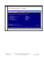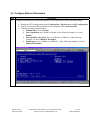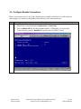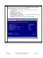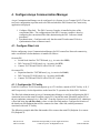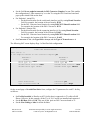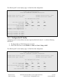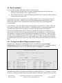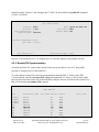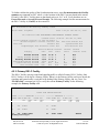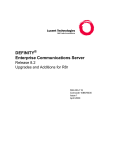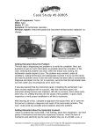
1
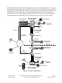
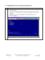
Avaya Solution & Interoperability Test Lab
Application Notes for RAD IPmux-14 TDMoIP Gateway with
Avaya Communication Manager - Issue 1.0
Abstract
These Application Notes describe the configuration steps required to support DS1 Converter
remote Port Network connectivity over an IP network using the RAD Data Communication
IPmux-14 TDMoIP Gateway and Avaya S8700 Media Server Multi-Connect configuration
running Avaya Communication Manager. Features and functionality were validated and
performance testing was conducted in order to verify operation under load. Information in
these Application Notes has been obtained through interoperability compliance testing and
additional technical discussions. Testing was conducted via the DeveloperConnection Program
at the Avaya Solution and Interoperability Test Lab.
BS; Reviewed:
SPOC 2/14/2005
Solution & Interoperability Test Lab Application Notes
©2005 Avaya Inc. All Rights Reserved.
1 of 22
RAD-IP-Mux.doc
1. Introduction
These Application Notes describe the compliance-tested configuration utilizing RAD Data
Communication’s IPmux-14 TDMoIP Gateway and Avaya S8700 Media Server Multi-Connect
configuration running Avaya Communication Manager, to transport DS1 Converter Remote Port
Network connectivity (T1/E1s) over an IP network.
RAD IPmux-14 is a TDMoIP gateway that enables the TDM E1/T1 circuits to be extended over an
IP/Ethernet network by extending voice and signaling protocols transparently over packet networks.
The IPmux-14 provides Circuit Emulation (CE) services over IP using TDMoIP (CE). The device
supports 1 to 4 T1 or E1 TDM facilities and converts the data streams coming from its TDM ports
into packets that are extended over the Fast Ethernet network port, and vice versa.
Avaya S8700 Media Server Multi-Connect configuration provides for remote Port Networks (remote
PNs) which are remotely located from the main Port Network (main PN). Remote PNs located
within 5 miles may be coupled using fiber-optic cable. When the remoting distance between the
main PN and the remote PN exceeds 5 miles, coupling is provided using a DS1 Converter Complex.
A DS1 Converter Complex consists of a pair of DS1 Converter boards (TN1654) and their
associated T1/E1 facilities. The Converter Complex is installed in place of the conventional fiber
and supports from 1 to 4 T1 or E1 facilities, providing a total of 92 T1 channels (or 120 E1 channels)
in each direction between the main PN and the remote PN.
The compliance testing focused on transporting T1/E1 facilities associated with the DS1 Converter
boards over an IP network utilizing RAD IPmux-14 TDMoIP Gateway.
1.1. Sample Network Configuration
The tested network configuration is shown in Figure 1.
The network is configured for two locations – the main site and the remote site. The main site
consists of Avaya S8700 Media Server Multiconnect configuration that includes an Avaya MCC1
Media Gateway, which will be referred to as the main Port Network (main PN). The remote site
consists of Avaya SCC1 Media Gateway, which will be referred to as a remote PN. An Avaya DS1
Converter TN1654 board is installed in the main PN and another TN1654 board is installed in the
remote PN. Four T1 (E1) links are provided between these two DS1 Converter boards over an IP
network. The IP transport of T1/E1 is enabled by a RAD IPmux-14 device at each site. The IP
network consists of an Avaya P333R Stackable Switch at the main site and an Avaya P333T
stackable switch at the remote site. At each site, the TDM side of the IPmux-14 is connected to the
DS1 Converter board via 4 T1 (E1) cables, and the IP side is connected to an Avaya Stackable
switch. Both the main PN and the remote PN support a mix of analog, digital and IP phones, and fax
machines. Another fax machine is also connected in the public network. A modem for making data
calls is supported in the remote PN.
BS; Reviewed:
SPOC 2/14/2005
Solution & Interoperability Test Lab Application Notes
©2005 Avaya Inc. All Rights Reserved.
2 of 22
RAD-IP-Mux.doc
Both the main PN and remote PN derive synchronization from a common public source - a public T1
(E1). At the main site, a public network T1 (E1) is connected to a T1 (E1) board in the Avaya MCC1
Media Gateway. At the remote site, a public network T1 (E1) is connected to an External port on the
RAD IPmux-14 device, and this device transmits the synchronization clock to the Avaya SCC1
Media Gateway via the T1 (E1) links associated to the DS1 Converter board. This configuration is
also applicable to Avaya DEFINITY® Servers that support DS1 Converter TN1654 Complex.
Avaya MCC1 Gateway
(Main Port Network)
Avaya S8700 Media
Server
Analog Telephone
Avaya Digital
Telephones
IP
Fax
Analog Trunk
T1/E1 over Avaya DS1
Converter TN1654
circuitpack
T1/E1 for
Synchronization
RAD IPMux-14
IP
Avaya P333R
Stackable Switch
Avaya 4600 Series
IP Telephone
Fax
PSTN
Main Site
IP
Remote Site
Avaya 4600 Series
IP Telephone
Avaya P333T
Stackable Switch
Analog
TelePhone
T1/E1 for
Synchronization
IP
RAD IPMux-14
Fax
T1/E1 over Avaya DS1
Converter TN1654
circuitpack
Avaya Digital
Telephones
Analog Telephone
PC with
Modem
Avaya SCC1 Media Gateway
(Remote Port Network)
Figure 1: Network Configuration
BS; Reviewed:
SPOC 2/14/2005
Solution & Interoperability Test Lab Application Notes
©2005 Avaya Inc. All Rights Reserved.
3 of 22
RAD-IP-Mux.doc
2. Equipment and Software Validated
The following equipment and software/firmware were used for the sample configuration provided:
Equipment
Avaya S8700 Media Server in MultiConnect
Configuration
Avaya MCC1 Media Gateway (main Port Network)
• Switch Node Interface TN573B
• DS1 Converter TN1654 with “special” Y cable
Avaya SCC1 Media Gateway (remote Port Network)
• Expansion Interface TN570B
• DS1 Converter TN1654 with “special” Y cable
Avaya P333R Multilayer Stackable Switch
Avaya P333T-PWR Power over Ethernet Stackable
Switch
Avaya 4612 IP Telephones
Avaya 8410D Digital phones using TN2224B
Analog phones
Analog trunk (Central Office)
AvayaT1/E1 trunk circuit packs - TN464F
Synchronization source from public network
• TN464F T1/E1
RAD IPmux-14 TDMoIP Gateway
Software/Firmware
2.0.1 (R012x.01.0.221.1)
V4
V6
V8
V6
3.9.1
4.0.17
1.8.1
V5
V16
1.0
3. Configure IPmux-14 TDMoIP Gateway
The IPmux-14 is configured via a terminal control session. There are four basic configuration steps
that need to be followed when deploying IPmux-14, as follows:
1.
2.
3.
4.
IP Configuration – Setting the device host IP address
Physical layer configuration – Setting the TDM parameters (line type, synchronization, etc.).
Creating bundles – Allocating timeslots to bundles.
Connecting bundles – Directing the bundles to remoteIPmux-14 unit.
BS; Reviewed:
SPOC 2/14/2005
Solution & Interoperability Test Lab Application Notes
©2005 Avaya Inc. All Rights Reserved.
4 of 22
RAD-IP-Mux.doc
3.1. Managing IPmux-14 via Terminal Control Session
Step
1.
Description
a. Connect IPmux-14 to a PC equipped with an ASCII terminal emulation application (for
example Procomm).
b. Launch the terminal emulator application and set its port parameters to 115.2kbps, 8
bits/character, 1 stop bit, and no parity. Set the terminal emulator to ANSI VT100
emulation.
c. Login as a superuser, entering user name as su and appropriate password.
d. A main menu appears.
BS; Reviewed:
SPOC 2/14/2005
Solution & Interoperability Test Lab Application Notes
©2005 Avaya Inc. All Rights Reserved.
5 of 22
RAD-IP-Mux.doc
3.2. Configure IP Parameters
Step
1.
Description
a. Display the Host IP menu (Configuration > System > Host IP), and configure the IP address
and the mask of the host.
b. In the following example, the Host IP address is 192.168.50.200, the IP mask is
255.255.255.0, and the Default gateway is 192.168.50.1. The Host IP address of the IPmux14 unit at remote site (not shown here) is 192.168.60.200 and the IP mask is 255.255.255.0.
BS; Reviewed:
SPOC 2/14/2005
Solution & Interoperability Test Lab Application Notes
©2005 Avaya Inc. All Rights Reserved.
6 of 22
RAD-IP-Mux.doc
3.3. Configure T1/E1 Parameters at the Physical Layer
Step
Description
1. Configure T1 or E1
a. Display the Physical Layer menu (Configuration > Physical layer)
b. Configure the TDM Interface Type as T1 or E1. In the following example, the TDM
interface type is set to T1.
2.
Select a T1/E1 for TDM Configuration
a. Display the TDM Configuration menu (Configuration > Physical layer > TDM
Configuration)
b. Type F to select one of the four T1 or E1 interfaces.
BS; Reviewed:
SPOC 2/14/2005
Solution & Interoperability Test Lab Application Notes
©2005 Avaya Inc. All Rights Reserved.
7 of 22
RAD-IP-Mux.doc
Step
Description
3. TDM Configuration
Configure the following TDM parameters for a T1 or E1.
a. Admin Status: Admin Status – set it to Enable. This enables the T1/E1 link.
b. Transmit clock source –
a. For the IPmux-14 at the remote site, set the clock source to External. Make sure
the External clock port on the IPmux-14 at the remote site is connected to a public
T1 (or public E1). See Section 4.2 for more details on clocking (Synchronization).
b. For the IPmux-14 at the main site, set the clock source to Adaptive.
c. Line type – Unframed G.703 (for E1) or Unframed (for T1).
d. Line code – b8zs for T1. This field is not displayed for E1 and is internally set to hdb3.
The following example shows a T1 configuration for an IPmux-14 at main site.
Note: The Transmit clock source is set to Adaptive
The T1 configuration at the remote site is the same as above, except that the Transmit clock
source is set to External.
BS; Reviewed:
SPOC 2/14/2005
Solution & Interoperability Test Lab Application Notes
©2005 Avaya Inc. All Rights Reserved.
8 of 22
RAD-IP-Mux.doc
Step
Description
4. The following example shows the E1 configuration for an IPmux-14 at the remote site.
Note: The Line type is configured as Unframed G.703 and the Transmit clock source is set to
External source.
BS; Reviewed:
SPOC 2/14/2005
Solution & Interoperability Test Lab Application Notes
©2005 Avaya Inc. All Rights Reserved.
9 of 22
RAD-IP-Mux.doc
Step
Description
5. The following example shows a T1 configuration for an IPmux-14 at main site.
Note: The Transmit clock source is set to Adaptive
BS; Reviewed:
SPOC 2/14/2005
Solution & Interoperability Test Lab Application Notes
©2005 Avaya Inc. All Rights Reserved.
10 of 22
RAD-IP-Mux.doc
3.4. Configure Ethernet Parameters
Step
Description
1. Configure an Ethernet port for network interface to an IP network, as in the following example:
a. Display the ETH Configuration menu (Configuration > Physical layer > Eth Configuration)
b. Type F to select the Ethernet interface to be configured. Select Network=Eth1.
c. Configure the following parameters:
• Channel State: set it to Enable.
• Auto Negotiation: set it Enable or Disable. In the following example, it is set to
Disable.
• Max capability advertised: Set it to 10BaseT or 100BaseT. In the following
example, it is set to 100baseT full duplex.
• Default type: Set it to 10BaseT or 100BaseT. In the following example, it is set to
100baseT full duplex.
BS; Reviewed:
SPOC 2/14/2005
Solution & Interoperability Test Lab Application Notes
©2005 Avaya Inc. All Rights Reserved.
11 of 22
RAD-IP-Mux.doc
3.5. Configure Bundle Connections
IPmux-14 associates each T1 (E1) with a bundle. Select a bundle on the IPmux-14 at the main site,
and configure it to connect to the bundles on the IPmux-14 unit at the remote site.
Step
Description
1. Select a Bundle ID
a. Display the Connection menu (Configuration > Connection).
b. Select a Bundle ID. By selecting a bundle number, a TDM link (1-4) is specified.
c. In the following example, Bundle ID 1 specifies the first TDM (T1) link.
BS; Reviewed:
SPOC 2/14/2005
Solution & Interoperability Test Lab Application Notes
©2005 Avaya Inc. All Rights Reserved.
12 of 22
RAD-IP-Mux.doc
Step
Description
2. Connect the bundles
Display the Bundle connection configuration menu (Configuration > Connection > Bundle
connection configuration). Configure the following parameters:
a. Destination IP address – IP address of IPmux-14 at remote site. For example,
192.168.60.200
b. Next Hop – For example, 192.168.50.1.
c. Connection Status – Enable.
d. Destination bundle – For example 1.
e. OAM Connectivity – Enable. The device starts transmitting at full rate after it detects an
active unit on the other side of the line.
f. Jitter Buffer – 5 msec. This sets the desired depth of the jitter buffer.
3.
Repeat steps 1 and 2 for other TDM links.
BS; Reviewed:
SPOC 2/14/2005
Solution & Interoperability Test Lab Application Notes
©2005 Avaya Inc. All Rights Reserved.
13 of 22
RAD-IP-Mux.doc
4. Configure Avaya Communication Manager
Avaya Communication Manager can be configured via a System Access Terminal (SAT). There are
two basic configuration steps that need to be followed when the DS1 Remote Port Connectivity
application is deployed:
1. Configure Fiber link - The DS1 Converter Complex is installed in place of the
conventional fiber. The configurartion of the DS1 Converter complex is done by
configuring the conventional fiber link, administering the DS1 Converter related
parameters.
2. Synchronization – Configure and verify that the main PN and remote PN derive
synchronization from a common source.
4.1. Configure Fiber Link
Before configuring Avaya Communication Manager for DS1 remote Port Network connectivity,
make sure that the relevant hardware is installed as follows:
On main PN,
• Switch Node Interface TN573B board, (e.g., in carrier slot 1E20).
• DS1 Converter TN1654 board, (e.g., in carrier slot 1E21).
• Connect TN573B and TN1654 with a TN1654 Y cable.
On remote PN,
• Expansion Interface TN570B board, (e.g., in carrier slot 11A01).
• DS1 Converter TN1654 board, (e.g., in carrier slot 11A02).
• Connect TN570B and TN1654 with a TN1654 Y cable.
4.1.1. Configure the T1 Facility
Each DS1 Converter TN1654 board supports up to 4 T1 facilities, named as DS1C facility A, B, C
and D respectively. Set the dipswitches on the board for T1 operation for all the DS1C facilities.
The fiber-link administration in Avaya Communication Manager is used for configuring the DS1C
connection between the main PN and the remote PN. Consider the main PN and the remote PN as
the two endpoints connected via a “fiber link”. From the System Access Terminal (SAT), administer
a fiber link using the add fiber-link x, where x is the fiber link number. Configure the location of
the boards on each Endpoint that will be connected to form a fiber link, and the parameters
associated with each T1 facility.
The following example adds fiber-link number 11 to connect the main PN (Endpoint 1) to remote
PN (Endpoint 2):
BS; Reviewed:
SPOC 2/14/2005
Solution & Interoperability Test Lab Application Notes
©2005 Avaya Inc. All Rights Reserved.
14 of 22
RAD-IP-Mux.doc
•
•
•
•
Set the field Is one endpoint remoted via DS1 Converter Complex? to yes. This enables
the configuration of ‘fiber connectivity’ over the T1s using the DS1 Converter board and
pops up the related fields on the form.
For Endpoint 1 (main PN),
o Set the board location for the switch node interface (sni) by setting Board Location
field. For example, the location of the sni board is 1E20.
o Set the DS1 Converter board location by setting DS1CONV Board Location field.
For example, the location of the DS1 Converter is 1E21.
For Endpoint 2 (remote PN),
o Set the board location for the expansion interface (ei) by setting Board Location
field. For example, the location of the EI board is 11A01.
o Set the DS1 Converter board location by setting DS1CONV Board Location field.
For example, the location of the DS1 Converter is 11A02.
Set Converter to Yes , the Type field to Avaya, and the Type of Transceivers to A
The following SAT screen displays Page 1 of the fiber-link configuration:
display fiber-link 11
Page
1 of
FIBER LINK ADMINISTRATION
Fiber Link #: 11
Is one endpoint remoted via DS1 Converter Complex? yes
ENDPOINT-1
(A-PNC)
Board Location: 01E20
Board Type: sni
DS1CONV Board Location: 01E21
DS1CONV Board Type: TN1654
ENDPOINT-2
(A-PNC)
Board Location: 11A01
Board Type: ei
DS1CONV Board Location: 11A02
DS1CONV Board Type: TN1654
Fiber Translation:
Type of Transceivers: A
Converter? yes
Converter Type: Avaya
On the second page of the add fiber-link x form, configure the T1 parameters for each T1 facility,
as follows:
•
•
•
Set Facility Installed to Yes for each T1 facility that is connected via T1 cable to RAD
IPmux-14 device. In this example, all the T1s (A, B, C and D) are installed and connected.
Set the Bit Rate field to 1.544. This sets all the ports on DS1 Converter board to T1.
Set the Line Coding to b8zs for all the facilities.
BS; Reviewed:
SPOC 2/14/2005
Solution & Interoperability Test Lab Application Notes
©2005 Avaya Inc. All Rights Reserved.
15 of 22
RAD-IP-Mux.doc
2
The following SAT screen displays page 2 of the fiber-link configuration:
display fiber-link 11
Page
2 of
2
FIBER LINK ADMINISTRATION
A-PNC DS1 CONVERTER (DS1CONV) ATTRIBUTES
DS1CONV Board Location: 01E21
DS1CONV Board Type: TN1654
DS1CONV Board Location: 11A02
DS1CONV Board Type: TN1654
DS1 CONVERTER FACILITIES
Facility Installed?
Bit Rate:
Facility Startup Idle Code:
Line Coding:
Framing Mode:
DS1CONV-1 Line Compensation:
DS1CONV-2 Line Compensation:
Facility
Facility
Facility
Facility
A
B
C
D
Circuit
Circuit
Circuit
Circuit
ID:
ID:
ID:
ID:
RAD
RAD
RAD
RAD
A
yes
1.544
11101000
b8zs
B
yes
C
yes
D
yes
b8zs
b8zs
b8zs
1
1
1
1
1
1
1
1
A
B
C
D
4.1.2. Configure the E1 Facility
Configuring the E1 facility follows the same steps described in Section 4.1.1, with the following
differences:
•
•
The dipswitches on TN1654 board are set for E1.
On the fiber-link form, set the Bit Rate to 2.048 and Line Coding to hdb3.
The following SAT screen displays page 2 of the fiber-link configuration:
display fiber-link 11
Page
2 of
FIBER LINK ADMINISTRATION
A-PNC DS1 CONVERTER (DS1CONV) ATTRIBUTES
DS1CONV Board Location: 01E21
DS1CONV Board Type: TN1654
DS1CONV Board Location: 11A02
DS1CONV Board Type: TN1654
DS1 CONVERTER FACILITIES
Facility Installed?
Bit Rate:
Facility Startup Idle Code:
Line Coding:
CRC?
Line Termination:
BS; Reviewed:
SPOC 2/14/2005
A
yes
2.048
11101000
hdb3
no
75/*
B
yes
C
yes
D
yes
hdb3
hdb3
hdb3
75/*
75/*
75/*
Solution & Interoperability Test Lab Application Notes
©2005 Avaya Inc. All Rights Reserved.
16 of 22
RAD-IP-Mux.doc
2
4.2. Synchronization
For successful operation of this application, it is imperative that:
• Both the main PN and the remote PN derive synchronization from a facility that can be
traced to a common public source - a public T1 (E1).
• The remote PN must derive the synchronization from the DS1-C facility on a DS1 Converter
board resident in the remote PN.
As described in Section 1.1, at the main site, a public network T1 (E1) is connected to a T1 (E1)
board in the Avaya MCC1 Media Gateway to provide Synchronization to the main PN. All the
boards on the main PN derive synchronization from this common source, including the DS1
Converter board.
At the remote site, the remote PN must derive synchronization from the DS1-C facility, which can
be traced to a common source such as Public T1. Normally the DS1-C facility at the remote site is
connected to the public network, and hence it can derive synchronization from a public T1.
However, in this application, the DS1-C facility is connected to an IPmux-14, and IPmux-14 is
connected to an IP network. The IP network cannot provide (or transport) the T1 Synchronization.
The alternative is using the External Clock timing mode supported by IPmux-14. Connect a public
network T1(E1) to an External port on RAD IPmux-14 device at remote site. This results in IPmux14 deriving synchronization traceable to a common public source, and in turn this device transmits
the synchronization clock to the remote PN via the T1 (E1) links associated with the DS1 Converter
board.
4.2.1. Configure the Main PN Synchronization Source
Using the SAT, configure the Synchronization Source for main PN by using the change
synchronization command. For the Primary field, enter the location of the T1 (or E1) board that is
connected to the public network. In the following example the Primary is set to 01C15.
change synchronization
Page
1 of
10
SYNCHRONIZATION PLAN
SYNCHRONIZATION SOURCE (circuit pack location)
Stratum: 4
Primary: 01C15
Location
03C17
03B08
03B07
03C16
03C15
02D17
Type
DS1
DS1
DS1
DS1
DS1
DS1
Secondary:
CIRCUIT PACKS AVAILABLE FOR SYNCHRONIZATION
Name
Slip
Location Type Name
Abacus b18 PRI
n
02C17
DS1
Abacus b12 PRI
isdn pri 2
n
02C16
DS1
Abacus b11 PRI
isdn pri 1
n
01D17
DS1
Abacus-PBX27
Abacus b17 PRI
n
02B15
DS1
Abacus-PBX27
Abacus b16 PRI
n
02B16
DS1
Abcus
Abacus b15 PRI
n
02B18
DS1
Abacus
Slip
n
n
n
n
n
n
Synchronization can also be derived from another Avaya Media Gateway, e.g., System G, as long as
System G is deriving synchronization from a public network. In that case, connect a T1 between the
BS; Reviewed:
SPOC 2/14/2005
Solution & Interoperability Test Lab Application Notes
©2005 Avaya Inc. All Rights Reserved.
17 of 22
RAD-IP-Mux.doc
main PN and the System G, and configure the T1 (DS1) on the main PN using add ds1 command
via SAT, as follows:
add ds1 c15
Page
1 of
2
DS1 CIRCUIT PACK
Location:
Bit Rate:
Line Compensation:
Signaling Mode:
01C15
1.544
1
isdn-ext
Name: synch for main PN
Line Coding: b8zs
Framing Mode: esf
Interface Companding: mulaw
Idle Code: 11111111
Slip Detection? n
Near-end CSU Type: other
Here the T1 board in slot 01C15 is connected to a T1 board in another Avaya Media Gateway.
4.2.2. Remote PN Synchronization
As stated in Section 4.2, connect the External Clock port on the IPmux-14 to a T1 from public
network (a common source to the main PN).
To verify that the remote PN is deriving synchronization from the DS1-C facility on the DS1
Converter board, enter the test tone-clock x long command on SAT, where x is the location of the
tone-clock board on the remote PN. In the following example, the tone-clock board for remote PN is
11a. Verify that the test number 150 is passed.
test tone-clock 11a long
TEST RESULTS
Port
maintenance Name
11AXX07
11AXX07
11AXX08
11AXX08
11A
11A
11A
11A
11A
11A
ETR-PT
ETR-PT
ETR-PT
ETR-PT
TDM-CLK
TDM-CLK
TDM-CLK
TDM-CLK
TONE-PT
TONE-PT
BS; Reviewed:
SPOC 2/14/2005
Alt. Name Test No. Result
42
43
42
43
148
150
151
574
90
40
Error Code
PASS
PASS
PASS
PASS
PASS
PASS
PASS
PASS
PASS
PASS
Solution & Interoperability Test Lab Application Notes
©2005 Avaya Inc. All Rights Reserved.
18 of 22
RAD-IP-Mux.doc
To further validate the quality of the Synchronization source, enter list measurements ds1-facility
summary xy command on SAT, where x is the location of the DS1 Converter board in the remote
PN and y is the DS1-C facility name on that board such as A, B, C or D. Verify that there are no
Errored Seconds or Severely Errored Seconds. The following example lists the measurements for
the DS1-C facility A (11a02a) on the remote PN.
list measurements ds1-facility summary 11a02a
Switch Name: SIL-pbx27
Date: 1:03 pm
FRI OCT 15, 2004
DS-1 FACILITY LINK PERFORMANCE MEASUREMENTS SUMMARY REPORT
Counted Since:
Valid 15-Minute Intervals in Last 24 Hours:
Seconds Elapsed In Current Interval:
Test: N/A
Pattern:
Loopback/Span Test Bit-Error Count:
Category
10:40 am FRI OCT 15, 2004
7
406
ESF Error Events: N/A
N/A
Synchronized: N/A
N/A
Test Duration: N/A
Worst 15-Minute Interval
Date
Time
Count
Errored Seconds
Bursty Errored Seconds
Severely Errored Seconds
Unavailable/Failed Seconds
Controlled Slip Seconds
Loss Of Frame Count
10/15
10/15
10/15
10/15
N/A
N/A
12:40
12:40
12:40
12:40
N/A
N/A
0
0
0
0
N/A
N/A
24-Hour
Count
Current
Interval Count
0
0
0
0
N/A
N/A
N/A
N/A
N/A
N/A
N/A
N/A
4.2.3. Primary DS1-C Facility
The DS1-C facility carrying control and signaling traffic is called a Primary DS1-C facility. Only
DS1-C facility A or B can be a Primary facility. When A is the Primary facility and it goes down, the
signaling and control traffic is switched to B, making B the Primary facility, and vice versa. Use
“list fiber-link” command via SAT to verify the current Primary Facility. In the following
example, the Primary Facility is B.
list fiber-link
FIBER LINK ADMINISTRATION
FIBER -------- ENDPOINT 1 -------LINK# TYPE A-PNC DS1
B-PNC DS1
LOC
CONV LOC
CONV
LOC
LOC
-------- ENDPOINT 2 -------TYPE A-PNC DS1
B-PNC DS1
LOC
CONV LOC
CONV
LOC
LOC
1
sni
01E02
ei
01B02
2
sni
01E03
ei
02A01
ei
11A01 11A02
11
sni 01E20 01E21
Primary Facility:B
BS; Reviewed:
SPOC 2/14/2005
Solution & Interoperability Test Lab Application Notes
©2005 Avaya Inc. All Rights Reserved.
DS1
CONV
TYPE
TN1654
19 of 22
RAD-IP-Mux.doc
5. Interoperability Compliance Testing
The interoperability compliance testing focused on transporting the T1/E1s utilized for Avaya DS1
Converter Remote Port Network connectivity, over an IP network using the RAD IPmux-14
TDMoIP Gateway device. The testing was performed for transporting four T1s from an Avaya
MCC1 Media Gateway (main PN) at the main site to an Avaya SCC1 Media Gateway (remote PN)
at the remote site. The same tests were repeated for transporting four E1s.
5.1. General Test Approach
The general approach was to validate the execution of maintenance tests for the remote PN and make
a variety of calls over the main PN and remote PN. The test calls included voice calls, data calls
using modems, and fax calls – off net and on-net calls. Synchronization of remote PN with main PN
is critical to the success of this solution and was configured and validated. The main objectives were
to verify that:
•
•
•
•
•
•
•
•
•
The remote PN is up and working when the DS1 Converter link is established.
The hardware objects on the remote PN, such as DS1-C facility, tone-clock, fiber-link etc.,
are working properly and can be maintained via Avaya Communication Manager
maintenance test commands.
Resetting the hardware such as DS1 Converter board or remote port network, or resetting the
Avaya Communication Manager works properly.
The on-net voice calls (from main PN to remote PN, or remote PN to main PN) and the offnet voice calls (remote PN to public network via main PN) have good quality and no static or
echo.
Modem calls from the remote PN to the public network via the main PN are successful.
On-net and Off-net Fax calls are successful.
DTMF tones can be transmitted successfully from remote PN to the public network.
The maximum possible calls over the DS1 Connector complex (over 4 T1s or 4 E1s) can be
established.
The system operates properly during and after a load test.
5.2. Test Results
All test cases completed successfully. With the appropriate synchronization of main PN and remote
PN, the voice, data and fax calls were successful. The following behavior was observed in one of the
scenarios:
1. DTMF tones are transmitted from remote PN to public network successfully. However, when
the digit keys are pressed and released on the telephone, even after the key is released, the
DTMF tone is heard for another fraction of a second as if it is being echoed.
BS; Reviewed:
SPOC 2/14/2005
Solution & Interoperability Test Lab Application Notes
©2005 Avaya Inc. All Rights Reserved.
20 of 22
RAD-IP-Mux.doc
6. Verification Steps
The following steps may be used to verify the configuration and connectivity:
• Verify that the remote PN is deriving synchronization from the DS1C facility, as described in
Section 4.2.2.
• Verify that a voice call from remote PN to main PN is successful.
7. Support
For technical support on the RAD product line, consult www.rad.com or contact RAD Technical
Support at phone number 1-800-444-7234.
8. Conclusion
These Application Notes describe the compliance-tested configuration utilizing the RAD Data
Communication IPmux-14 TDMoIP Gateway and Avaya S8700 Media Server Multi-Connect
configuration running Avaya Communication Manager, to support DS1 Converter Remote Port
Network connectivity (T1/E1) over an IP network.
9. Additional References
The following documents are relevant to these Application Notes:
1) Administrator’s Guide for Avaya Communication Manager, Issue 8, June 2004, Document
Number 555-233-506.
2) Avaya Maintenance Alarms Reference, Nov 2003, Document Number 555-245-102.
3) Avaya Maintenance Commands Reference, Nov 2003, Document Number 555-245-101.
4) RAD IPmux-14 TDMoIP Gateway Installation and Operation Manual
Additional product documentation for Avaya products may be found at http://support.avaya.com and
for RAD products at http://www.rad.com.
BS; Reviewed:
SPOC 2/14/2005
Solution & Interoperability Test Lab Application Notes
©2005 Avaya Inc. All Rights Reserved.
21 of 22
RAD-IP-Mux.doc
©2005 Avaya Inc. All Rights Reserved.
Avaya and the Avaya Logo are trademarks of Avaya Inc. All trademarks identified by ® and ™
are registered trademarks or trademarks, respectively, of Avaya Inc. All other trademarks are the
property of their respective owners. The information provided in these Application Notes is
subject to change without notice. The configurations, technical data, and recommendations
provided in these Application Notes are believed to be accurate and dependable, but are
presented without express or implied warranty. Users are responsible for their application of any
products specified in these Application Notes.
Please e-mail any questions or comments pertaining to these Application Notes along with the
full title name and filename, located in the lower right corner, directly to the Avaya
DeveloperConnection Program at [email protected].
BS; Reviewed:
SPOC 2/14/2005
Solution & Interoperability Test Lab Application Notes
©2005 Avaya Inc. All Rights Reserved.
22 of 22
RAD-IP-Mux.doc