1
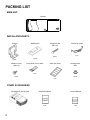
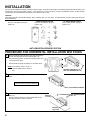
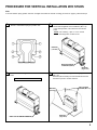
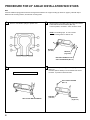
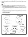
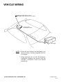
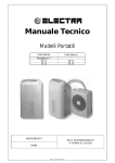
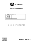
SP-11CDP
DIGITAL AUDIO/COMPACT DISC CHANGER
COMPACT
10 DISC AUTO CHANGER
COMPACT DISC AUDIO CHANGER SYSTEM
DIGITAL AUDIO
MODEL SP-11CDP
10-DISC CD CHANGER
INSTALLATION MANUAL
PACKING LIST
MAIN UNIT
Changer
SP-11CDP
DIGITAL AUDIO/COMPACT DISC CHANGER
COMPACT
OPEN
10 DISC AUTO CHANGER
COMPACT DISC AUDIO CHANGER SYSTEM
DIGITAL AUDIO
INSTALLATION PARTS
Stud Bracket
Bracket
Hexagonal Bolt
(M6 x 15)
5 Meter Din Cable
4 pcs.
1 pc.
2 pcs
2 pcs
Machine Screw
(M4x 10)
Screw Hole Cover Labels
Index seal sheet
Hexagonal Nut
(M6)
1 pc.
4 pcs.
4 pcs.
1 pc.
OTHER ACCESSORIES
2
CD Magazine (P/N SP11M)
Installation Manual
Owner's Manual
1 pc.
1 pc.
1 pc.
BEFORE INSTALLING THE UNIT
Transport Lock Screws
TRANSIT BOLTS
(2 RIGHT SIDE, 1 LEFT SIDE)
The mechanism in the CD changer is "locked" into place during shipment by the
transport screws. Be sure to remove the screws prior to installation.
l Caution l
After removing the transport lock screws, place a piece of masking tape over
each screw hole. The tape will keep out dust , which could cause the unit
to malfunction.
Installation and Wiring Precautions
1
To prevent a short-circuit,
l Be sure to turn off the ignition and remove the negative (-) battery cable, prior to installation.
l Connect power wires last.
Note
If the changer is to be installed in a car that is equipped with an on-board drive or navigation computer, do not disconnect
the battery cable. If the cable is disconnected, the computer memory may be lost. Under these conditions, use extra
caution during installation, to prevent a short circuit.
2
Do not install the unit in the following locations.
l Locations exposed to direct sunlight.
l Where hot air is discharged from the car heater.
l In areas subject to extreme temperatures.
3
Incorrect installation can cause the sound to "skip" when playing a disc.
Mount the unit firmly in place, using the supplied brackets and screws.
4
Be careful not to damage the car wiring.
5
l Be sure to use the supplied screws.
l Be careful not to snag any wires when tightening screws.
l Do not use any of the screws that are part of the brake or steering system, to install the unit.
6
l This unit cannot be installed on either side or up-side down. Installation in such positions will cause the mechanism
to malfunction.
3
INSTALLATION
The unit can be installed horizontally, vertically or at a 45° angle. The position of the built-in anti-vibration springs (left and right side), must
correspond to the mounting position chosen. If the springs are not set correctly for the type of installation chosen, the anti-vibration
compensation will not be effective and vibration may cause the disc to skip.
CAUTION
After setting the built-in anti-vibration springs, place masking tape over the holes. The tape will keep out dust, which could cause the
unit to malfunction.
HORIZONTAL INSTALLATION
Set the 2 anti-vibration springs to
position "0".
VERTICAL INSTALLAITON
Set the 2 anti-vibration springs to
position "90".
45° ANGLE INSTALLATION
Set the 2 anti-vibration springs to
position "45°".
ANTI-VIBRATION SPRINGS POSITION
PROCEDURE FOR HORIZONTAL INSTALLATION W/O STUDS
1
Attach a bracket to each side of the unit, using the machine
screws with integral flat and lock washers (M4 x 10).
In the horizontal position, use bracket mounting holes 1 and
1' as shown at the right.
Set anti-vibration springs to position "0" as shown above.
NOTE: Use masking tape to cover unused mounting holes on sides of
unit.
2
1
2
3
1
2
3
MACHINE SCREW WITH FLAT
AND LOCK WASHERS (M4 x 10)
Determine unit mounting location, and drill four mounting
holes.
Never mount the unit near the fuel tank.
DRILL HOLES 4MM IN DIAMETER
3
Secure the unit in place, using four self-tapping screws
(M5 x 12).
Use RTV (silicone sealer) on screw threads and around
the holes to prevent moisture intrusion.
SELF-TAPPING SCREWS
(M5 x 12)
BRACKET
(Left Side)
BRACKET
(Right Side)
4
PROCEDURE FOR VERTICAL INSTALLATION W/O STUDS
Note
If the anti-vibration spring position has been changed and verified for vertical mounting (as shown on page 4), start with step 2.
1
Set the 2 anti-vibration springs to position "90".
2
Attach bracket to each side of the unit, using machine
screws with integral flat and lock washers. (M4 x 10).
In the vertical position, use holes 2 and 2' as shown
at left.
NOTE: Use masking tape to cover unused
mounting holes on sides of unit.
BRACKET
(Left Side)
MACHINE SCREWS
w/WASHERS (M4x10)
BRACKET
(Right Side)
3
Determine the mounting location, and drill four mounting
holes.
Never mount the unit near the fuel tank.
4
Mount the unit in place, using four self-tapping screws
(M5 x 12).
Use RTV (silicone sealer) on screw threads and around
the holes to prevent moisture intrusion.
SELF-TAPPING
SCREWS (M5 x 12)
BRACKET
(Left Side)
DRILL HOLES 4MM IN DIAMETER
BRACKET
(Right Side)
5
PROCEDURE FOR 45° ANGLE INSTALLATION W/O STUDS
Note
If the anti-vibration spring position has been changed and verified for 45° angle mounting (as shown on page 4), start with step 2.
Determine the mounting location, and drill four mounting holes.
1
Set the 2 anti-vibration springs to position "45°".
2
Attach bracket to each side of the unit, using the machine
screws with flat and lock washers (M4x 10).
In the 45 position, use holes 1 and 3' as shown at left.
NOTE: Use masking tape to cover unused
mounting holes on sides of unit.
BRACKET
(Left Side)
BRACKET
(Right Side)
MACHINE SCREW WITH FLAT
AND LOCK WASHERS (M4 x 10)
4
3
Never mount the unit near the fuel tank.
Mount the unit in place, using four self-tapping screws
(M5 x 12).
Use RTV (silicone sealer) on screw threads and around
the holes to prevent moisture intrusion.
SELF-TAPPING SCREWS
(M5 x 12)
DRILL HOLES 4MM IN DIAMETER
6
BRACKET
(Left Side)
BRACKET
(Right Side)
PROCEDURE FOR CHANGER INSTALLATION USING MOUNTING
STUDS
Note:
Make sure the anti-vibration spring position has been changed and verified for the proper angle mounting (as shown on page 4).
1
Determine mounting location. If unit is to be installed onto mounting studs located under carpet, lift carpet to expose metal chassis
and mark position of each stud as shown below in detail A and B.
2
Insert two hexagonal mounting bolts through underside of each bracket (detail A) and mount stud bracket in position using two
self-tapping screws into metal chassis. Hex bolt heads should be flush with underside of stud bracket.
3
Replace carpet over bracket studs (detail B), mark position of stud end of each bolt, and cut holes in carpet so bolts protrude through
carpet.
4
Proceed with unit mounting by positioning unit mounting brackets over protruding hex bolts as shown in details C, D and E. Secure
mounting brackets to bolts using hex lock nuts.
5
If mounting studs are to be located directly on mounting surface with no carpet in between, mount changer directly on studs as
illustrated below in details A, C, D and E.
STUD BRACKET MOUNTING
ARRANGEMENT
(Detail A)
STUD BRACKET MOUNTING
UNDER A CARPET
(Detail B)
SELF-TAPPING SCREWS
(M5 x 12)
CARPET
STUD BRACKET
STUD BRACKET
HEX BOLT (M6 x 15)
CHASSIS
VERTICAL INSTALLATION
WITH STUD BRACKET
(Detail C)
SUSPENDED INSTALLATION
WITH STUD BRACKET
(Detail D)
HORIZONTAL INSTALLATION
WITH STUD BRACKET
(Detail E)
HEX NUT (M6)
HEX NUT (M6)
CHANGER MOUNTING
BRACKET
STUD BRACKET
CHANGER MOUNTING
BRACKET
STUD BRACKET
CHANGER MOUNTING
BRACKET
HEX NUT (M6)
STUD BRACKET
7
VEHICLE WIRING
Mating 8-pin DIN socket on rear of
compatible radio chassis (see note 1 below).
Car Stereo with
CD Changer Controls
DIN
ca
ble
(8pin
)
CD changer
NOTE: 1. Check with your Audiovox car audio dealer to be
sure your stereo is directly compatible with this
CD changer.
2. Wiring instructions for use with FM Modulator/
Commander Systems are included with the
CDC-MC1, CDC-MCR2, P-MC3 and P-MCR4
accessories.
© 2000 AUDIOVOX CORP., HAUPPAUGE, NY
Printed in China
128-5779A