1
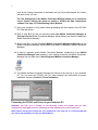
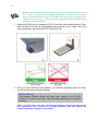
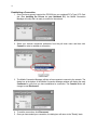
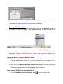
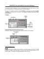
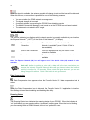
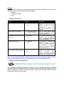
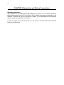
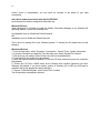
1 Table of Contents CHAPTER 1 Welcome to the Mobile Connection Manager About this Guide Checklist Owner Records About your PC3220 Wireless PC Card Modem What is the Mobile Connection Manager? Caring for your PC3220 What is CDMA The Basics 3 3 3 3 3 4 4 4 5 CHAPTER 2 Installing the Mobile Connection Manager and PC3220 on Your Notebook PC Installation Precautions System Requirements Installing the Mobile Connection Manager Software Installing Fourelle Venturi Data Compression Connecting the PC3220 and Drivers to your Notebook PC Account Activation with Verizon Wireless Establishing a Connection Powering OFF/ON the PC3220 Exiting the Mobile Connection Manager (MCM) Removing the PC3220 from your Notebook PC 6 6 6 7 8 9 11 12 13 13 14 CHAPTER 3 Using the Mobile Connection Manager Understanding The Indicator Area and Icons Signal Strength Indicator Service Indicator Data Compression Roaming Status Connection Indicator Connection Time Byte Counter Service Status Dialog Box Understanding the Action Buttons Settings Settings: General Tab Settings: Connection Profiles Tab Settings: About Tab Call Log Help System Tray Shortcut 15 15 15 16 16 16 17 17 17 17 18 19 19 19 20 20 21 21 2 Table of Contents CHAPTER 4 System Tray Mode (Connection Status Icon and Menu) System Tray Icon System Tray Menu 22 22 23 CHAPTER 5 Understanding Alert Windows Express NetworkSM (1xRTT) and Quick 2 NetSM (14.4kbps) Alerts Connection Lost Alert Software Mismatch Alert Power On Card Alert Connection in Progress Alert Delete Connection Profile Confirmation Reset Call Log Information 24 24 24 24 24 24 25 25 CHAPTER 6 Networking and Dial-up Connections Windows Networking 26 26 CHAPTER 7 Frequently Asked Questions CHAPTER 8 Regulatory Information and Safety and Hazards CHAPTER 9 Technical Specifications Environmental Specifications Radio Frequency and Electrical Specifications Software Specifications Mechanical Specifications 27 29 32 32 32 32 33 CHAPTER 10 Licensing Agreement CHAPTER 11 Limited Warranty 34 37 3 CHAPTER 1 Welcome to the Mobile Connection Manager Congratulations and thank you for purchasing the PC3220 Wireless PC Card Modem! The PC3220 is a dual band CDMA2000 1X product that enables you to communicate wirelessly from your laptop. Now that you are equipped with a wireless modem, you no longer need to carry chargers, cables, telephone jack converters, and batteries. This product is simple to install and use. The Mobile Connection Manager software allows you to easily monitor your connections and customize your settings. NOTE: Before using the PC3220, you MUST review the Safety Information outlined on page 30. About this Guide This User’s Guide contains all the information you will need to properly install and use your PC3220 Wireless PC Card Modem. Before you can begin using the PC3220, it is essential that you follow the proper instructions for installation. You must load the Mobile Connection Manager software located on the CD-ROM that was included in your kit before you insert the PC3220 into your notebook PC. This initial setup process just takes a few minutes and you’ll soon be on your way to wireless freedom. Checklist Make sure that the following items are included in the kit when you unpack it: o A PC3220 Wireless PC Card Modem o The Installation CD which contains the Mobile Connection Manager Software, the Fourelle Venturi 2.1 Data Compression Software, and the Owner’s Manual o A Quick Start Guide Owner Records Be sure to keep handy your PC Card’s ESN number, located at the bottom of your card, for easy reference. Record your information here for easy reference: ESN Number: ___________________________________ About your PC3220 Wireless PC Card Modem The PC3220 is a wireless PC Card modem designed to fit into a Type II PC Card slot available on most notebook PCs. This uniquely designed card allows you to connect to the Internet, send and receive email efficiently, connect to your company’s network, and maximize productivity when away from the office. Power Management Designed to take advantage of the power management and system overhead benefits offered by the 32-bit CardBus electrical interface that extends battery life. CardBus: another name for “advanced PC Card,” the CardBus interface works at lower battery voltage and operates at a greater speed than the standard PC Card interface. 4 Unique Antenna Design The PC3220 includes a proprietary antenna design that optimizes data rate transfer speeds, sensitivity, and increases power efficiency. Other Features and Benefits § A Type II PCMCIA format supporting the CardBus I/O interface § Supports North American CDMA Cellular (800 MHz) and PCS (1900 MHz) bands (analog not supported) § Based on the QUALCOMM MSM5100 chipset § Supports IS-95A/B and CDMA2000 1xRTT Release 0 § Optimized data rates of up to 153.6 kbps on both the forward and reverse links § Provides dial-up, Express Networksm (1xRTT) and Quick 2 Netsm (14.4kbps) services What is the Mobile Connection Manager? The Mobile Connection Manager is an application designed to assist you in managing the PC3220. With this application you can easily monitor and customize your connections. The Mobile Connection Manager Software guides you through the wireless connection process. Similar to a mobile phone display, the user interface of the Mobile Connection Manager instructs you when to insert the PC3220 into your laptop, advises you on network availability, displays the time of your session and amount of data being transferred and received, and when your connection becomes dormant. Other features allow you to customize your settings, review your connection history, and access a digital help file. Caring for your PC3220 Storage: § When not in use, fold the antenna down and store in a compartment where the card can be protected from being crushed or broken. § Do not apply adhesive labels to the PC3220. This may cause the card to jam inside the PC Card slot of your notebook PC. § The antenna extends freely, do not forcefully hyper-extend the antenna. This may cause it to break. § The PC3220 should easily fit into the PC Card slot. Forcing the PC3220 into the PC Card slot may cause considerable damage. § Your PC3220 should be stored in a dry and clean place. Protect your card from liquids, dust and excessive heat. What is CDMA? Your PC3220 operates on a wireless cellular network called CDMA (Code Division Multiple Access). CDMA is a digital spread-spectrum wireless technology that offers reliable, high speed, bi-directional throughput of up to 144 kbps for email, corporate databases and all the 5 services of the Internet. The PC3220 is a high performance card that enables you to both send and receive data/email at maximum network rates. Often times when using a dial-up connection, a "network busy" signal appears. That's because there are "bottlenecks" slowing down the network. With the spread spectrum technology of CDMA these frustrating bottlenecks are eliminated. In fact, CDMA technology allows a network to handle more calls than competing digital technologies. Today, over 100 million consumers worldwide rely on CDMA technology for quality voice communications and reliable, high-speed data. What about privacy? The secure CDMA network is designed with digital coding that is recognized only by the base station and unintelligible to eavesdroppers. For more information on CDMA, visit the CDMA Development Group website: www.cdg.org The Basics Before you can begin using the PC3220 you will need to load the software on your notebook PC and configure the PC3220. Here is a brief overview of the steps outlined in the next section: ü Install the Mobile Connection Manager software, located on the Installation CD ü Insert the PC3220 into your notebook’s PC Card slot and install the drivers ü Activate your account when prompted by the Activation Wizard ü Connect to your Service Provider's high-speed 1xRTT CDMA Network CAUTION: Do not insert the PC3220 into your notebook’s PC Card slot until you are prompted to do so by the Mobile Connection Manager software wizard. Failure to do so will result in fatal errors to your PC. Follow the installation guidelines outlines in Section 2: Installing the Mobile Connection Manager and PC3220 on your Notebook PC. 6 CHAPTER 2 Installing the Mobile Connection Manager and PC3220 on Your Notebook PC Installation Precautions WARNING: DO NOT insert the PC3220 before you install the Mobile Connection Manager software onto your notebook PC. Once you install the Mobile Connection Manager software, you will be prompted to insert the PC3220 into the Type II PC Card slot. CAUTION: Before beginning the installation process, it is recommended that you quit all open applications. WARNING: Once the card is inserted, do not physically remove the PC3220 from the PC Card slot until you have completed the Unplug/Eject process. Removing the card improperly may cause a fatal error to your PC. NOTE: If you have previous versions of the Mobile Connection Manager or Venturi applications installed on your notebook PC, you will need to remove the application(s) by utilizing the Add/Remove Programs Windows utility. Once removed, proceed with the installation procedures of the current version located on your Installation CD. Uninstalling the Mobile Connection Manager and/or Fourelle Venturi software: Windows XP 1. Go to: Start>Control Panel>Add/Remove Programs 2. Select Mobile Connection Manager and/or Fourelle Venturi and click Change/Remove 3. Next select Remove and click OK to proceed when prompted 4. You will need to restart your Laptop PC in order to complete the uninstall Windows 2000 1. Go to: Start>Settings>Control Panel>Add/Remove Programs 2. Select Mobile Connection Manager and/or Fourelle Venturi and click Change/Remove 3. Next select Remove and click OK to proceed when prompted 4. You will need to restart your Laptop PC in order to complete the uninstall Windows 98 and ME 1. Go to: Start>Settings>Control Panel>Add/Remove Programs 2. Select Mobile Connection Manager and/or Fourelle Venturi and click Add/Remove 3. Next click OK to proceed when prompted 4. You will need to restart your Laptop PC in order to complete the uninstall System Requirements Before you begin the installation process, check that your notebook PC supports the following system requirements. 1. Your PC3220 functions in notebook PCs with these Windows® operating systems: Windows® 98SE Windows® ME Windows® XP Windows® 2000 NOTE: This card is not designed to function in handhelds and Pocket PCs and does not support Windows CE. 7 2. In order to install the PC3220 and the Mobile Connection Manager software, these minimum system resources are required: Card slots: Disk-Drive: Memory: Disk Space: Processor: Dial Up Networking: Type II PC Card slot (Cardbus) CD-ROM 32 MB 14MB Pentium 150MHz or higher DUN bound to TCP/IP NOTE - Windows 98: You may need the original Microsoft Windows 98 Installation CD. NOTE: If you are planning to upgrade your Microsoft operating system, you will need to uninstall the Mobile Connection Manager first. Once the Mobile Connection Manager is removed, proceed with the operating system upgrade. After these steps are complete, you will need to reinstall the Mobile Connection Manager. Installing the Mobile Connection Manager Software The Installation CD that was included in the PC3220 kit is equipped with the Mobile Connection Manager software. This software is required for installation and is essential for optimum performance of your PC3220. 1. Insert the Installation CD into your CD-ROM drive. 2. The Setup program should launch automatically and a Welcome window will appear. NOTE: If the Setup program does not launch automatically, select Start>Run and enter d:\Setup.exe, where d is the designation for the CD-ROM drive. 3. Click Next on the Mobile Connection Manager Setup Welcome Window. 4. Please read the Licensing Agreement carefully and click Yes to agree to the terms. 5. Click Next to install the software in the default folder. You may choose to install a different folder by clicking the Browse button. 6. If you prefer to have the Mobile Connection Manager launch automatically each time your notebook PC starts up, ensure the Run Mobile Connection Manager at Start up checkbox is checked. If you prefer to add the Mobile Connection Manager shortcut to your desktop, ensure the Desktop Shortcut checkbox is checked. Click Next. 7. Wait for the Setup Status to load 100% and the window will close automatically. 8. Installing the Venturi data compression software is recommended for accelerated performance. If you choose to install Venturi at this time: Windows 2000/XP/ME: Click Yes to install Venturi and proceed to step 9. 8 If you prefer to install Venturi later: Windows 2000/XP: If you choose to install Venturi later, select No and click Finish. Now proceed to step 18. Your notebook PC will not restart. Windows ME: If you choose to install Venturi later, select No and click Yes to restart your PC. Continue to step 18, once your PC restarts. Windows 98: You will need to manually install the Venturi software should you decide to install at this time or later: a. Once the "Installation Complete" screen appears, click Finish. (If you haven’t saved and closed other active applications and critical files, do so at this time). b. You must restart your notebook PC before the new settings will take effect. Click Yes to restart your notebook PC. c. Once your notebook PC does reboot, you will need to manually install Venturi. Go to Start>Run and enter d:\Setup.exe, where d is the designation for the CD-ROM drive. Select Fourelle Venturi 2.1 and click OK. Installing Fourelle Venturi Data Compression 9. If you haven’t saved and closed other active applications and critical files, do so at this time and click OK. 10. Wait while the Venturi Setup prepares the InstallShield™ Wizard. This window will close automatically. 11. To begin installation of the Venturi, click Next. 12. Read the Licensing Agreement carefully and click Yes to agree to the terms. 13. Review the Readme document and click Next. 14. Click Next to install the Venturi software to the default folder. If you prefer to install it to a different folder, click the Browse button. 15. A command box will appear briefly. No action is required when this screen appears; it will close automatically. 16. Before clicking Finish, close any open programs and save critical files. Your notebook PC will restart automatically. Once Venturi is installed on your notebook PC, this icon will appear in the system tray: . The “ X ” through the Venturi icon, signifies that Venturi is “off ” (the application is not running). Once an Internet connection is established with the Mobile Connection Manager, the icon will change to look like this: , signifying that the application is now “on”. While Venturi is actively compressing data the icon will transform into an animated tornado. As 9 soon as the Internet connection is terminated and you have disconnected, the Venturi will return to the “off” icon. Tip: The Settings tool in the Mobile Connection Manager allows you to control the use of Venturi, offering the option to enable or disable the data compression software. See page 19, Understanding Action Buttons. 17. Allow your computer to fully reboot before proceeding with the insertion of the PC3220 PC Card and drivers. 18. Skip to step 20 if you did not check the option Run Mobile Connection Manager at Start up from the Mobile Connection Manager Setup window (see step 6, Installing the Mobile Connection Manager). 19. Skip to step 21 if you did check Run Mobile Connection Manager at Start up from the Mobile Connection Manager Setup window (see step 6, Installing the Mobile Connection Manager). 20. In order to manually launch Mobile Connection Manager, double-click on the Mobile Connection Manager icon located on your desktop or access the Mobile Connection Manager from the Start menu: Start>Programs>Mobile Connection Manager. 21. The Mobile Wireless Connection Manager will launch at the start up of your notebook PC. Do not insert the PC3220 until you have followed the instructions for proper installation outlined in Section 2: Driver Installation. Connecting the PC3220 and Drivers to your Notebook PC WARNING: Once the card is inserted, do not physically remove the PC3220 until you have completed the Unplug/Eject process. Removing the card improperly may cause a fatal error. NOTE: Before inserting the PC3220 into your notebook PC’s PC Card slot, it is recommended that you remove the Installation CD from your CD-ROM drive. 10 driver: a program that extends the operating system to support a device such as a PC Card; or a program that enables an application to use a device such as a printer. Hardware devices such as PC Cards must each have the proper driver installed in order to run. 2. A driver acts like a translator between the device and programs that use the device. 1. Insert the PC3220 into your notebook PC’s PC Card Slot with the label facing up. Then, raise the antenna so that it is fully extended and pointed up at a 90° angle. Use in any other configuration may exceed FCC RF Exposure Limits. 2. Once you have inserted the card properly, your Windows operating system will notify you that new hardware has been detected. Windows XP only: The Hardware Detection Wizard will launch upon insertion of the PC3220. Follow the on screen instructions. This three-step wizard process will perform five times. NOTE: You may hear a short beep each time the PC3220 is inserted and removed from your notebook PC. This is normal. It is an audible notification from your notebook PC communicating that it recognizes new hardware. 11 Account Activation with Verizon Wireless Once the PC3220 is properly inserted into the Type II PC Card slot of your notebook PC, the Activation Wizard will automatically appear. (In order to use your PC3220, you must have an account set up with Verizon Wireless). The process of setting up an account is called activation. Follow these steps for activation: The Activation Wizard ‘Welcome’ window provides two methods for activation: ‘Auto Activation’ and ‘Manual Activation’. After reviewing the dialog on the Activation Wizard ‘Welcome’ window, select your activation preference, Auto or Manual. 1. Write down the MIN (Mobile Identification Number) and SID (System ID) numbers [This information can be found on the packaging materials found inside the box, if the PC3220 was shipped to you.] Tip: Keep these numbers handy, you will be asked to enter these if you selected Manual Activation. Activation Code: 000000 MIN: ________________________________ SID: _________________________________ 2. The Activation Process has been automated for your convenience. a. To enable Auto Activation, click Auto b. To initiate Manual Activation, click Manual (You will need to provide the Activation Code, MIN and SID.) 3. Follow the on-screen instructions of the Activation Wizard. a. Auto Activation: 1. If you selected Auto Activation, follow the on-screen instructions and wait for the Wizard to automatically configure the account. 2. Now click OK to automatically reset the PC3220 and complete activation. b. Manual Activation: 1. Follow the on-screen instructions. 2. You will be asked to enter an Activation Code. Enter six zeroes (000000) and click Next. 3. Enter the MIN and SID that were provided with your card and then click Next. 4. If the information is correct, click Yes. If no, select No and re-enter the information when prompted. 5. Click Finish to complete Activation. Wait a few moments for the PC3220 to automatically reset. You are now ready to use the PC3220 on the Verizon Wireless network. * For further assistance, contact Verizon Wireless, toll-free, at 1- (800) 922-0204. NOTE: If you have not activated your PC3220, an Activation Alert Notification will be displayed once you click the Connect button explaining that you must activate your card in order to establish a connection. 12 Establishing a Connection 1. Once you have properly inserted the PC3220 into your notebook PC's Type II PC Card slot (See Installing the Drivers to your Notebook PC), the Mobile Connection Manager will notify that it is ready to connect to the network. 2. Select your network connection preference from the pull down menu and then click Connect in order to establish a connection. 3. The Mobile Connection Manager will take a few moments to connect to the network. The dialog box at the bottom of the Mobile Connection Manager window will display the word Connected to notify that you have established a connection. The Connect button will change to read Disconnect. 4. To end the connection, click Disconnect. 5. Once you have ended your connection, the dialog box will return to the "Ready" state. 13 Note: A "No Service" message is displayed when the PC3220 cannot locate the network. "Connected" message is displayed once a connection is established. Powering OFF/ON the PC3220 In order to Power Off the Mobile Connection Manager click on the System Tray Icon and the System Tray Menu will appear. Select Power Off Card. In order to Power On the Mobile Connection Manager, click Power On Card. WARNING: Do not eject the PC3220 from your notebook until you have followed the Unplug/Eject Hardware instructions for proper removal. Removing the card improperly may cause a fatal error to your PC. Exiting the Mobile Connection Manager (MCM) 1. When you have completed your current session, click Disconnect on the Mobile Connection Manager to ensure that you are disconnected from the network; this will make the data connection inactive. 2. Next, click on the Mobile Connection Manager icon located in the system tray of your notebook PC and select Exit from the shortcut menu. This will close the Mobile Connection Manager and the icon will disappear from the system tray. Removing the PC3220 from your Notebook PC 1. Click on the Mobile Connection Manager icon found in the system tray. 14 2. Select Exit from the menu. (The icon will disappear from the system tray). 3. After the Mobile Connection Manager has exited, go to the system tray and click on the Unplug and Eject Hardware icon. Windows 2000 & ME Windows XP Windows 98SE 4. A menu will appear: Windows 98 and ME ONLY: Select "Stop AirPrime USB Open Host Controller" Windows 2000 ONLY: Select “ Standard OpenHCD USB Host Controller” Windows XP ONLY: Select “ Lucent USB OpenHost Controller” 5. Once the "Safe to Remove Hardware" message appears, click OK. 6. After the “Safe to Remove Hardware” message appears, click OK. 7. You may now remove the PC3220 from your notebook. When removing the PC3220, always grip it by the sides of the card rather than from the top. Pulling on the antenna over time may damage the card. If available, use the Card Ejector tool on your laptop. Tip: Another option to safely remove hardware is the system tray menu shortcut. 1. Left-click on the Unplug/Eject Hardware icon and a menu will appear: Windows 98 and ME ONLY: Select "Stop AirPrime USB Open Host Controller" Windows 2000 ONLY: Select “ Standard OpenHCD USB Host Controller” Windows XP ONLY: Select “ Lucent USB OpenHost Controller” 2. Once the "Safe to Remove Hardware" message appears, click OK. 3. You may now remove the PC3220 from your notebook. 15 CHAPTER 3 Using the Mobile Connection Manager The Mobile Connection Manager is turned on automatically when your laptop starts up, unless you turned this option “off” in the previous section, Software Installation. This view of the Mobile Connection is called Full Mode. An alternate view, called the System Tray Mode, is described later in this section, titled: System Tray Mode (Connection Status Icon and Menu). Full Mode: Understanding The Indicator Area and Icons Depending on the PC3220’s operating mode, different indicators will be displayed. Signal Strength Indicator The Signal Strength icon displays when the Mobile Connection Manager is turned on. The bars indicate the strength of the radio signal. Four bars signify that the signal strength is at its maximum peak. The strength will change depending on where you are. 16 When no signal is available, the antenna symbol will change to red and the bars will be dimmed. When this occurs, no connection is possible for one of the following reasons: • • • • • You are outside of a CDMA network coverage area The signal strength is too weak A network problem is preventing the PC3220 from obtaining service The Mobile Connection Manager is not turned on or the PC3220 has not been inserted The antenna is not raised to a 90° angle Service Indicator or The Service Indicator icon displays which network service is currently available at your location, the Express NetworkSM (1xRTT) or the Quick 2 Net NetworkSM (14.4kbps). Express Network Connection This default icon signifies that the Express Network is available (even if Quick 2 Net is also available) Quick 2 Net Connection This icon signifies that only the Quick 2 Net network is available No service The icon is dimmed when no service is available Note: The Express Network (3G) icon will appear even if the Quick 2 Net (2G) network is also available. data call: similar to making a voice call, a data call is the term used when you access the Internet. Express Network data calls go dormant when the Internet activity is inactive for ~30 seconds. When a data call goes dormant, you are not being charged for airtime. Quick 2 Net calls do not go dormant. Data Compression The Data Compression icon appears when the Fourelle Venturi 2.1 data compression tool is active. When the Data Compression icon is dimmed, the Fourelle Venturi 2.1 application is inactive. See Settings to learn about enabling and disabling this utility. Roaming Status The Roaming Status icon indicates the roaming status of your PC3220. When the indicator is “on” (solid black) you are roaming within a “preferred” roaming area. When the icon is blinking, you are roaming within a CDMA network, but not in a “preferred” zone. 17 When the indicator is “off” (dimmed), you are within the local coverage area of Verizon Wireless. You are not roaming. Note: Your coverage area and billing charges depend upon your Verizon Wireless and the type of account you have. There may be surcharges for roaming service that varies based on whether you are in a preferred roaming area or a non-preferred roaming area. If there is no roaming agreement between Verizon Wireless and the local carrier, you may be unable to complete calls in a nonpreferred zone. Connection Indicator The Connection Indicator icon signifies that a connection is established. The icon will flash while you are in the process of connecting and will then remain static once you are connected. If the Connection Indicator icon is dimmed, there is no connection nor is a connection attempt in process. Connection Time The Connection Time field displays the duration of the current data call or connection. The timer begins as soon as a connection is established. The time format is 00hrs: 00min: 00sec. Byte Counter The Byte Counter displays the amount of data transferred and received during each session, as soon as a connection is established in measurements of Kilobytes and Megabytes. For 0 to 999KB: “XXX KB” format (I.e., “7 KB,” “68 KB,” or “768 KB”) For 1MB and up: “XXX.X MB” format (I.e., “1.0 MB,” “3.2 MB” or “343.3 MB”) Service Status Dialog Box The Service Status Dialog Box explains the current status of your PC3220. 18 Service Status Dialog Description Associated icon graphic Please insert Card No card is detected The system tray icon displays gray Card is Off PC Card is powered off The system tray icon displays gray Ready Service is available or appear in the Indicator area and the system tray icon displays blue No Service No service is available Connecting Attempting to make a connection Connected A connection is established (Quick 2 Net, Express Network active or dormant) Dormant/Connected A connection is established but no data transfer is in progress The system tray icon displays yellow Disconnecting Disconnecting the current call None Call Dropped Call is dropped; transient state returning to Ready None This icon will be gray This icon will flash Understanding the Action Buttons The Action Buttons allow you to customize the Mobile Connection Manager and monitor your connections. 19 Settings The Settings tool allows you to customize the Mobile Connection Manager. Once you click on this button a pop-up window with three tabs will appear: § General § Connection Profiles § About Settings: General Tab Option Choices Enable Compression - On (default) - Off Start in System Tray Mode - In Full Mode (default) - In System Tray Mode Run Mobile Connection Manager at Start up - On (default) - Off Enable Call Drop Alert - On (default) - Off SM Express Network (1xRTT) and SM Quick 2 Net (14.4kbps) Alerts - On (default) - Off Description This option is turned "on" by default. If you prefer to set the Fourelle Venturi 2.1 data compression to remain "off" remove the checkmark in the checkbox. None of these options allow automatic placement of a data call upon card insertion. This default setting can be changed during installation. Refer to Installing the Mobile Connection Manager, step 5. This option is checked by default. It enables a pop-up window and audible alert when the connection is dropped. Applicable to Quick 2 Net and Dial-up Networking only. These options are checked by default. They enable pop-up window messages before connections to Express Network or Quick 2 Net are established. Note: The "Run Activation Wizard" button will guide you through the activation process. Refer to this tool, if the PC3220 still needs to be activated. (See Page 11, Activating the PC3220.) Settings: Connection Profiles Tab connection profile: a predefined or user-created profile that signifies a type of connection. (i.e. Express Network (1xRTT), Quick 2 Net (14.4kbps), or other). The Connection Profiles tab provides a summary of your connection profiles. The default connection profiles for Express Network and Quick 2 Net are created during installation and can neither be deleted nor edited. You have the option to add a new connection profile or edit an existing profile that you have created. 20 These three headers are displayed in the window: • Profile Name • Profile Number • Default profile (shows a checkbox for the default profile) Connection Profiles Buttons Button Function/Action Add Opens the Connection Profile Edit Window if you wish to add a new dial up connection profile. Delete If you prefer to delete one of the dial-up connection profiles, select the profile and click Delete. If no profile is selected, the button will be dimmed. An Alert will appear to confirm your choice about deleting a certain Connection Profile. (You cannot delete the default connection profiles for Express Network and Quick 2 Net). Edit If you prefer to edit a particular dial-up connection profile, highlight your selection and click Edit. The Connection Profile Edit Window will open. If no profile is selected or either Express Network or Quick 2 Net is selected, the edit option will be unavailable. Connect Allows you to make a connection using the selected profile. If no profile is selected, the option will be unavailable. Set as default Marks the currently selected connection profile as the default. If no profile is selected, the option is unavailable. Connection Profile Edit Window This window allows you to add a new connection profile or edit an existing profile. Field Format/Values Description Profile name 20 alphanumeric characters or punctuation marks Enter the name of the profile that will be displayed in the Connection Profile Window. Minimum length is 1 character. Phone number 3 or more digits, #, * Enter the destination phone number of the profile. This field is mandatory. User name 40 characters Enter the username to be submitted to the receiving modem. This field is optional. Password 20 characters Enter the password to be submitted to the receiving modem. An asterisk (*) will represent every entered character. This field is optional. Settings: About Tab The About Tab provides useful information about the your device. Call Log The Call Log lists a summary of all data calls made. A Window table appears displaying the following columns: 21 Column Name On-Screen Format Description Call Type Express Network Quick 2 Net Dial-up Networking Indicates the type of call initiated. Click on the Column name to sort by Call Type. Connection Name Text From Connection Profiles list (Express Network or Quick 2 Net) Phone number 15 digits Destination phone number or Caller ID, if available. For Quick 2 Net calls, this will be the number dialed. Date and Time YYYY MMM DD hh:mm am(or pm) Date when the data call was made. (MMM is the 3-character representation of the month). Time when the call is initiated. Click on the Column name to sort by Date and Time. Duration hh:mm:ss or mm:ss Duration of the call. Bytes In Examples: 7 KB, 68 KB, 768 KB, 3.2 MB, 343.3 MB, 1.3GB. Bytes Out Examples: 7 KB, 68 KB, 768 KB, 3.2 MB, 343.3 MB, 1.3GB. Note: You are able to sort/organize the view (ascending and descending) by any of the above six columns. Button Action Reset If there are some entries in the call log, a confirmation dialog will appear. If confirmed, purge all entries in the Call Log and reset the Last Reset Time to the current time. If there is no entry in the Call Log, no action is taken. Help The Help button links you directly to the digital help guide. System Tray Shortcut When viewing the Mobile Connection Manager in Full Mode, you have the option to “close” the window into System Tray Mode. The icon located in the System Tray communicates your connection status similarly to the Service Status dialog in Full Mode. By clicking on this shortcut, you are activating the System Tray Mode. 22 CHAPTER 4 System Tray Mode (Connection Status Icon and Menu) system tray: also known as the “status area,” the system tray is the section to the right of the Start button on your desktop. If you prefer to close the Full Mode view of the Mobile Connection Manager, you can still monitor your connections with the System Tray icon. This section outlines the functions of the System Tray icon and the System Tray shortcut menu. System Tray Icon Once the Mobile Connection is launched, an icon will appear in the System Tray of your notebook PC. This icon will change colors, according to the current status of your connection. Once you exit the Mobile Connection Manager, this icon will disappear. “System Tray Icon” Description Icon Color Tool Tip Ready- When the icon displays blue, it is ready to make a connection Mobile Connection Manager: Ready Connectingcurrently connection icon is flashing a Mobile Connection Manager: Connecting Connected- When the icon displays green, a connection is established and data transfer is in progress Mobile Connection Manager: Connected Dormant/Connected- When the icon displays yellow, a connection is established but no data transfer is in progress Mobile Connection Manager: Dormant/Connected No Service- When the icon displays red, the card has no service Mobile Connection Manager: No Service Off- When the icon appears gray this means that the power to the card is off Mobile Connection Manager: Card is Off No card is detected Mobile Connection Manager: Insert Card making 23 System Tray Menu By clicking on the System Tray icon, a menu becomes visible. Below is a list explaining the functions of each menu option. . Menu Item Action Availability when Card is not inserted Open Brings up Full Mode view Remains available Connect (or) Disconnect Select to connect or disconnect a Option is unavailable when data call icon is dimmed Power On Card (or) Power Off Card Select to power on/off the card Option is unavailable when icon is dimmed Settings Open Settings dialog Option is unavailable when icon is dimmed Help Brings up the Help file Remains available About Brings up the About Tab in the User Settings window Option is dimmed/unavailable Exit Terminates Mobile Connection Remains available Manager; The System Tray icon will disappear Note: When you select Exit from the menu, you are “exiting” the application/program. Once this action occurs, the icon will be removed from your system tray. (Remember the icon is only visible while the program is running). 24 CHAPTER 5 Understanding Alert Windows Alerts that are generated by the Mobile Connection Manager explain effects of certain actions you are enabling by selecting particular functions. You generally can exit an alert by selecting Yes, No or OK. You also have the option to “turn off” an alert either from the alert window itself, or by manually shutting it off. To manually shut off an alert, access the Settings tool in the Action Area of the Full Mode Mobile Connection Manager screen or click the System Tray Icon in the system tray of your notebook PC to access the shortcut menu. Following are different alerts that may appear during use. Express NetworkSM (1xRTT) and Quick 2 NetSM (14.4kbps) Alerts The Express Network alert will appear each time an Express Network data call is initiated. The Quick 2 Net alert will appear each time a Quick 2 Net data call is initiated. Select Continue to dismiss the alerts and proceed with your data call or Cancel to cancel the data call. You are able to turn off this alert for the future by clicking the checkbox at the bottom of the window. You may manually turn off these alerts by accessing the General tab in the Settings tool window. Connection Lost Alert A visual and audible alert occurs whenever a connection has been inadvertently lost, due to poor signal strength or being outside a local coverage area. Select OK to acknowledge the notice and close the window. You may manually turn off this alert by accessing the General tab in the Settings tool window. Software Mismatch Alert This alert will appear if the host software you are installing is older than modem software. Click OK to dismiss the dialog. NOTE: You may continue to use the PC3220 after closing the alert window, even with the software mismatch. Power On Card Alert If the PC3220 has been "Powered Off", an attempt to connect by clicking the Connect or Settings buttons will cause this alert to appear. Click Yes to close the alert window and card power on the PC3220 automatically. Click No to acknowledge that the card has been “Powered Off” and close the alert window. NOTE: You must turn the power on before making a connection. Access the shortcut menu by clicking on the System Tray icon and select Power On. Connection in Progress Alert A "Connection in Progress" or "Connection is still Active" alert message occurs if you attempt to select Exit or Power Off from the System Tray shortcut menu prior to terminating your connection. When a connection is in progress, you cannot exit or power off the PC3220 without first terminating the connection by clicking the Disconnect button from the Full Mode view or shortcut menu from the System Tray icon. 25 When this alert message appears, click Yes and your connection will be automatically terminated. Continue with your intended action. Click No to dismiss the alert message and keep the Mobile Connection Manager power on and connection active. Delete Connection Profile Confirmation If you decide to delete a dial-up connection from your Connection Profiles, a confirmation message will appear. Select Yes to delete the selected profile and return to the Connection Profile Tab. Select No to close the confirmation window and cancel or ignore the intended action. NOTE: Preset default profiles cannot be deleted. Reset Call Log Confirmation When you reset the Call Log a confirmation message will appear. Select Yes to confirm the deletion of the current entries and to reset the Last Reset Time. Select No to close the confirmation window and retain all current entries in the call log without resetting the Last Reset Time. 26 CHAPTER 6 Networking and Dial-up Connections Windows Networking After installation of the Mobile Connection Manager and drivers, the two default connection profiles (Express Network (1xRTT) and Quick 2 Net (14.4kbps)) will appear automatically on the Windows® “Network and Dial Up Connections” window. If you have added a new connection profile, it will also be displayed in this window. In order to create new connection profile, you will need to consult the Microsoft® Help files located in the Start Menu. 27 CHAPTER 7 Frequently Asked Questions Here are some answers to common questions regarding the PC3220: What is the Mobile Connection Manager? The Mobile Connection Manager is an application designed to assist you in managing the PC3220. With this application you can easily monitor and customize your connections. My PC3220 becomes noticeably hot after using it for a while, is this normal? Like all PC Cards, the PC3220 generates heat in its normal operation and is also heated by the host computer. For this reason it is recommended that you allow PC3220 to cool down after extensive operation so that it may become cool to the touch before you remove it from your notebook PC. What is the difference between Express Networksm (1xRTT) and Quick 2 Netsm (14.4kbps)? The Express Networksm (3G) is Verizon Wireless's digital network using 1xRTT technology with speeds bursting up to 144kbps. Quick 2 Netsm (2G), also known as Quick Net Connect, provides direct connection to the Internet with faster set up time. It functions somewhat like a standard 14.4k dial-up connection, with the exception that the time required to establish connection/session is much shorter. How fast will my connection be with the PC3220? If your card is functioning in an Express Network zone, the maximum speed you will experience is 144kbps, with average speeds between 50-70kbps. If you are attempting to connect in a Quick 2 Net coverage area, speeds will match that of a standard dial up connection. With the installation of the Fourelle Venturi data compression software, you will achieve accelerated performance. Which Operating System do I need in order to run the Mobile Connection Manager? You will need Windows® 98SE, 2000, ME, or XP to run the Mobile Connection Manager. The Mobile Connection Manager is not compatible with Windows CE, handhelds or Macintosh. How much space on my hard drive will the Mobile Connection Manager require? 14MB. The Installation CD includes the Mobile Connection Manager and optional applications, such as Venturi data compression software and Internet Explorer 6.0. For complete system requirements, see Installing the Mobile Connection Manager and the PC3220 on my Notebook PC on page 6. What is the Fourelle Venturi 2.1 Data Compression Software? Fourelle Venturi 2.1 Data Compression Software is an enhancing feature available with the PC3220. When you install and enable the Venturi software, located on your Installation CD, the compression will automatically be used where it is available on the network. In areas where the 28 Venturi server is implemented, you will notice an increase in the speed of your data connections. Am I able to make phone/voice calls with the PC3220? No, this particular model is designed for data calls only. Windows 98 Only: When attempting to Un-install or Install the Mobile Connection Manager on my Windows 98 operating system, I receive the following error: Un-installation error on Win98 with PowerControl.dll OR Installation error on Win98 with PowerControl.dll This is due to a missing file in your Windows system. To retrieve the file, please carry out the following: Windows 98 Users: 1. From the Start menu, select 'Programs - Accessories - System Tools - System Information' 2. A system information box appears. From the tools menu select 'System File Checker'. 3. This gives you two options. Select 'Extract one file from installation disk'. 4. Type 'regsvr32.exe' as the file to be restored 5. Insert the original Windows installation CD into the CD drive (and exit any start-up / install box that appears) 6. Choose the CD Drive 'Win98' folder as the 'Restore from' location (Assuming you have Windows 98 installed. If you have another version of Windows (95 or ME) you will need to substitute '98' by the appropriate version identifier.) 7. Choose 'C:\Windows\System' as the 'Save File in' location The file should be automatically retrieved. 29 CHAPTER 8 Regulatory Information and Safety This Section outlines important regulatory notices concerning your new PC Card. Regulatory Notices This device complies with Parts 15, 22, and 24 of the FCC rules. This PC card has been tested with the typical laptop computer with the side loading PCMCIA bay. This PC card must not be co-location or operated in conjunction with any other antenna or transmitter. Use of this device in any other configuration may exceed the FCC RF Exposure compliance limit. Operation of this device is subject to the following two conditions: 1. This device may cause harmful interference, and 2. This device must accept any interference received, including interference that may cause undesirable operations. AirPrime, Inc. stipulates that the antenna should be more than 1.5 cm (0.60”) from bystanders and 1.0cm (0.39”) from the user. When in use, the antenna should be fully extended upward at a 90-degree angle. FCC ID: PNF-PC3220P CAUTION: Unauthorized modification of changed not expressly approved could void compliance with RF exposure guidelines. WARNING- This equipment has been tested and found to comply with the limits pursuant to Part 15, 22, and 24 of the FCC Rules. These limits are designed to provide reasonable protection against harmful interference in an appropriate installation. This equipment generates, uses, and can radiate radio frequency energy and, if not installed and used in accordance with the instruction, may cause harmful interference to radio communication. However, there is no guarantee that interference will not occur in a particular installation. If this equipment does cause harmful interference to radio or television reception, which can be determined by turning the equipment off and on, the user is encouraged to try to correct the interference by one or more of the following measures: • Reorient or relocate the receiving antenna • Increase the separation between the equipment and receiver • Connect the equipment into an outlet on a circuit different from that to which the receiver is connected 30 • Consult the dealer or an experienced radio/TV technician for help WARNING- This digital apparatus does not exceed the Class B limits for radio noise emissions from digital apparatus as set out in the interference causing equipment standard entitled “Digital Apparatus,” ICES-003 of the Department of Communications. Cet appareil numerique respecte les limites de bruits radioelectriques applicables aux appareils numeriques de Classe B prescrites dans la norme sur le materiel brouilleur. “Appareils Numeriques,” NMB-003 edictee par le ministre de Communications. If you have purchased this product under a United States Government contract, it shall be subject to restrictions as forth in subparagraph (C)(1)(ii) of Defense Federal Acquisitions Regulations (DFARs) Section 252.227-7013 for Department of Defense contracts, and as set forth in Federal Acquisitions Regulations (FARs) Section 52.227-19 for civilian agency contracts or any successor regulations. If further government regulations apply, it is your responsibility to ensure compliance with such regulations. Safety Information This section outlines important liability and safety guidelines concerning your new PC Card. Important Notice Because of the nature of wireless communications, transmission and reception of data can never be guaranteed. Data may be delayed, corrupted (i.e., have errors) or totally be lost. Although significant delays or losses of data are rare when wireless devices such as the PC Card-Model PC3220 CDMA modem are used in a normal manner with a well constructed network, they should not be used in situations where failure to transmit or receive data could result in damage of any kind to the user or another party, including but not limited to personal injury, death or loss of personal property. No responsibility for damages of any kind resulting from delays or errors in data transmitted or received using the PC Card-Model PC3220 CDMA modem, or for failure of the PC Card-Model PC3220 to transmit or receive such data. Safety and Hazards Blasting Areas and Hospitals Do not operate the PC Card-Model PC3220 in areas where blasting is in progress, where explosive atmospheres may be present, near medical equipment, life support equipment, or any equipment which may be susceptible to any form of radio interference. In such areas the PC Card-Model PC3220 MUST BE POWERED OFF. It can transmit signals that could interfere with this equipment. Aircraft Do not operate the PC Card- Model PC3220 in any aircraft whether the aircraft is on the ground or in flight. In aircraft, the PC Card- Model PC3220 MUST BE POWERED OFF. When operating it can transmit signals that could interfere with various onboard systems. Driving The driver or operator of any vehicle should not operate the PC Card- Model PC3220 while in control of a vehicle. Doing so will detract from the driver or operator’s control and operation of that vehicle. In some jurisdictions, operating such communications devices while in control of a vehicle is an offense. 31 CHAPTER 9 Technical Specifications Environmental Specifications Operating temperature: Storage temperature: Humidity: Vibration stability: Drop: Contact discharge (Level 2): Air discharge (Level 3): - 20° to 60° C - 30° to 65°C 60° @ 15 - 95 % RH Sinusoidal vibration @ 15g peak Mechanical shock @ 50g peak 1 meter on vinyl surface +/- 1.5k V +/- 15k V Radio Frequency & Electrical Specifications Approvals: Interface type: Supply voltage: Current consumption: Transmitter power: Conducted Power (dBm): Radiated Power (dBm): Transmitting: (Max data rate): Transmit: Receive: Channel spacing: Frequency stability: Voice capability: FCC (parts 15&24, SAR) Type II PC Card 3.3V Sleep/Idle: 95mA Average in-use: 360mA Max. (Peak): 950mA 1900 MHz 25.0 800 MHz 23.5 1900 MHz 25.42 800 MHz 25.47 Forward link: 144 kbps Reverse link: 144 kbps 1850 to 1910MHz and 824 to 849MHz 1930 to 1990MHz and 868 to 894MHz 1.25MHz +/- 150Hz None Software Specifications CDMA specification: Data service: SMS (IS-637): FAX: IOTA: OTASP (IS-683A): OTAPA (IS-683A): PRL (preferred roaming list): Authentication: Voice: NAM: E911 & Position Location: TTY/Accessibility: Mobile IP: IS - 2000 Release 0 IS - 707A No Support No Support No Support Support No Support Support Support No Support Single No Support No Support No Support 32 WNP (wireless number portability): No Support Mechanical Specifications Dimensions (W x L x H): Weight: Power button: Headset jack: LED: Antenna: 54mm x 117mm x 5mm 40g No support No support Red/Green Vertically polarized dipole 33 CHAPTER 10 Licensing Information Licensing Information AIRPRIME INCORPORATED MOBILE CONNECTION MANAGER FOR THE PC3220 LICENSE AGREEMENT ATTENTION: CAREFULLY READ THIS AGREEMENT. BY CLICKING ON THE “YES” BUTTON OF THE LICENSING AGREEMENT WINDOW OR BY INSTALLING THIS APPLICATION, YOU INDICATE THAT YOU HAVE READ THIS AGREEMENT, HAVE THE AUTHORITY TO ENTER INTO THIS AGREEMENT, UNDERSTAND AND ACCEPT ALL THE TERMS AND CONDITIONS AND THAT YOU INTEND TO BE LEGALLY BOUND BY THE TERMS AND CONDITIONS OF THIS AGREEMENT. IF YOU DO NOT AGREE WITH THE TERMS AND CONDITIONS OF THIS AGREEMENT OR IF YOU DO NOT HAVE THE AUTHORITY TO ENTER INTO THIS AGREEMENT, CLICK ON THE “NO” BUTTON AND ERASE THE SOFTWARE FROM YOUR DATA STORAGE MEDIUM. 1. LICENSE TO USE. AirPrime, Inc. (“AirPrime”) hereby grants to you a non-exclusive, nontransferable license to use Mobile Connection Manager for the PC3220, which includes installation tools, documentation and other materials related to such software, subject to the terms and conditions of this Agreement. 2. PERMITTED USES. You may use Mobile Connection Manager solely for the purpose of running the PC3220 PC Card. 3. RESTRICTIONS ON USE. You may NOT: (a) use Mobile Connection Manager or make copies of it or any part of it, other than as expressly permitted in this Agreement; (b) publish or distribute all or substantially all of Mobile Connection Manager; (c) translate, reverse engineer, decompile or disassemble Mobile Connection Manager to create a derivative application; (d) sell, assign, transfer, rent, lease, sublicense or distribute rights to Mobile Connection Manager, in whole or in part; or (e) remove any proprietary notices or labels from Mobile Connection Manager. The restrictions in this section shall survive the termination or expiry of this Agreement. 4. CONFIDENTIALITY. Mobile Connection Manager and any information contained within, related to or about Mobile Connection Manager, are confidential and proprietary to AirPrime and its affiliates and suppliers. You agree not to disclose Mobile Connection Manager or such information to any third party without AirPrime’s prior written consent. This section shall survive the termination or expiry of this Agreement. 5. OWNERSHIP. United States and international copyright and intellectual property laws protect Mobile Connection Manager. AirPrime or its affiliates and suppliers own all rights to Mobile Connection Manager. AirPrime and its affiliates retain all rights in and to Mobile Connection Manager including, without limitation, the source code, object code, and any related information. By acquiring this application, you do not become the owner of Mobile Connection Manager but are entitled only to use Mobile Connection Manager in accordance with the terms of this Agreement. Nothing in this Agreement shall be construed as granting to you any other license, or invention, trade secret, patent, copyright, trademark or other intellectual property right of AirPrime. This section shall survive the termination or expiry of this Agreement. 6. NO WARRANTY. MOBILE CONNECTION MANAGER IS PROVIDED AND LICENSED “AS IS” AND USE OF MOBILE CONNECTION MANAGER IS AT YOUR RISK. AIRPRIME EXPRESSLY DISCLAIMS ALL WARRANTIES, REPRESENTATIONS OR CONDITIONS OF ANY KIND, EXPRESS, IMPLIED OR STATUTORY, INCLUDING BUT NOT LIMITED TO, BOTH (A) ANY WARRANTY OF MERCHANTABLE QUALITY OR FITNESS FOR A 34 PARTICULAR PURPOSE, AND (B) ANY WARRANTY THAT MOBILE CONNECTION MANAGER IS DELIVERED FREE OF ANY THIRD PARTY CLAIMS BY WAY OF INFRINGEMENT OR OTHERWISE. AIRPRIME DOES NOT WARRANT NOR MAKE ANY CONDITION OR REPRESENTATIONS THAT THE FUNCTIONS CONTAINED IN MOBILE CONNECTION MANAGER WILL MEET THE REQUIREMENTS OF THE LICENSEE, THAT THE OPERATION OF MOBILE CONNECTION MANAGER WILL BE UNINTERRUPTED OR ERROR-FREE OR VIRUS FREE OR THAT DEFECTS IN MOBILE CONNECTION MANAGER WILL BE CORRECTED. FURTHER, AIRPRIME DOES NOT WARRANT OR MAKE ANY CONDITIONS OR REPRESENTATIONS REGARDING THE USE OR THE RESULTS OF THE USE OF MOBILE CONNECTION MANAGER IN TERMS OF ITS CORRECTNESS, ACCURACY, RELIABILITY OR OTHERWISE. NO ORAL OR WRITTEN INFORMATION OR ADVICE GIVEN BY AIRPRIME OR OTHERS SHALL CREATE A WARRANTY, CONDITION OR REPRESENTATION OR IN ANY WAY EXTEND THE SCOPE OF THE “AS IS” PROVISION OF MOBILE CONNECTION MANAGER. This section shall survive the termination or expiry of this Agreement. You acknowledge and agree that you have no rights to any upgrades, modifications, enhancements or revisions that AirPrime may make to Mobile Connection Manager. AirPrime has no obligation to provide any support of any sort. 7. NO LIABILITY. THE ENTIRE RISK AS TO THE RESULTS AND PERFORMANCE OF THIS APPLICATION IS ASSUMED BY YOU. NEITHER WE NOR OUR AFFILIATES, DISTRIBUTORS, RESELLERS, SUPPLIERS, AGENTS, OFFICERS AND DIRECTORS SHALL HAVE ANY LIABILITY TO YOU OR TO ANY OTHER PERSON OR ENTITY FOR ANY DAMAGES HOWSOEVER CAUSED INCLUDING, BUT NOT LIMITED TO, DIRECT, INDIRECT, INCIDENTAL, SPECIAL, GENERAL, CONSEQUENTIAL, PUNITIVE OR EXEMPLARY DAMAGES WHATSOEVER INCLUDING, BUT NOT LIMITED TO, LOSS OF REVENUE OR PROFIT, DAMAGES TO PROPERTY OR PERSONS, LOST OR DAMAGED DATA, OR OTHER COMMERCIAL OR ECONOMIC LOSS, EVEN IF WE HAVE BEEN ADVISED OF THE POSSIBILITY OF SUCH DAMAGES OR THEY ARE FORESEEABLE, OR FOR CLAIMS BY ANY THIRD PARTY. OUR MAXIMUM AGGREGATE LIABILITY AND THAT OF OUR AFFILIATES, DISTRIBUTORS, RESELLERS, SUPPLIERS, AGENTS, OFFICERS AND DIRECTORS TO YOU SHALL NOT EXCEED THE AMOUNT PAID BY YOU FOR MOBILE CONNECTION MANAGER. THIS SECTION SHALL APPLY WHETHER OR NOT THE ALLEGED BREACH, DEFAULT, NONPERFORMANCE OR FAILURE IS A BREACH OF FUNDAMENTAL CONDITION OR TERM, OR A FUNDAMENTAL BREACH. This section shall survive the termination or expiry of this Agreement. 8. TERMINATION. This Agreement is effective until terminated. All rights granted to you under this Agreement will automatically terminate if you breach any of the terms and conditions of this Agreement. In addition, either of us may terminate this Agreement at any time upon notice to the other party, for convenience. Upon any termination of this Agreement, all licenses hereunder shall terminate, other than end-user licenses previously entered into in accordance with the provisions and, during the term, of this Agreement. Upon the termination of this Agreement, you will promptly erase all copies of Mobile Connection Manager in your possession and shall discontinue all reproduction and distribution of applications or other software developed that references elements of Mobile Connection Manager. 9. EXPORT REGULATIONS. All Software and technical data delivered under this Agreement are subject to US export control laws and may be subject to export or import regulations in other countries. You agree to comply strictly with all such laws and regulations and acknowledge that you have the responsibility to obtain such licenses to export, re-export, or import as may be required after delivery to you. 35 10. GENERAL. This Agreement is the entire agreement with respect to this application and supercedes any other agreements or discussions, oral or written. This Agreement may not be changed except by a written amendment signed by you and us. No provision of this Agreement may be waived except in writing by the party giving the waiver. Only a signing officer of AirPrime has the authority on our behalf to change or waive this Agreement. If any provision or term of these terms and conditions is determined to be invalid or unenforceable, the invalidity or unenforceability of that provision or term will not affect the validity or enforceability of the remaining provisions and terms or the validity or enforceability of that provision or term in any other jurisdiction. This Agreement shall be governed and construed in accordance with the laws of the State of California. If any provision of this Agreement is declared by a court of competent jurisdiction to be invalid, illegal or unenforceable, such provisions shall be severed from the Agreement and the other provisions shall remain in full force and effect. Should you have any questions concerning this Agreement, you may write to: AirPrime, Inc., Attn: Legal 2290 Cosmos Court Carlsbad, CA 92009 USA 36 CHAPTER 11 Limited Warranty Audiovox Communications Corp. (the Company) warrants to the original retail purchaser of this Audiovox CDMA2000 1X, PCMCIA Card, that should this product or any part thereof during normal consumer usage and conditions, be proven defective in material or workmanship that results in product failure within the first twelve (12) month period from the date of purchase, such defect(s) will be repaired or replaced (with new or rebuilt parts) at the Company’s option, without charge for parts or labor directly related to the defect(s). This Warranty extends only to consumers who purchase the product in the United States or Canada and it is not transferable or assignable. This Warranty does not apply to: (a) Product subjected to abnormal use or conditions, accident, mishandling, neglect, unauthorized alteration, misuse, improper installation or repair or improper storage; (b) Product whose mechanical serial number or electronic serial number has been removed, altered or defaced. (c) Damage from exposure to moisture, humidity, excessive temperatures or extreme environmental conditions; (d) Damage resulting from connection to, or use of any accessory or other product not approved or authorized by the Company; (e) Defects in appearance, cosmetic, decorative or structural items such as framing and non-operative parts; (f) Product damaged from external causes such as fire, flooding, dirt, sand, weather conditions, battery leakage, blown fuse, theft or improper usage of any electrical source. The Company disclaims liability for removal or reinstallation of the product, for geographic coverage, for inadequate signal reception by the antenna or for communications range or operation of the cellular system as a whole. To obtain repairs or replacement within the terms of this Warranty, the product should be delivered with proof of Warranty coverage (e.g. dated bill of sale), the consumer’s return address, daytime phone number and/or fax number and complete description of the problem, transportation prepaid, to the Company at the address shown below or to the place of purchase for repair or replacement processing. In addition, for reference to an authorized Warranty station in your area, you may telephone in the United States (800) 229-1235, and in Canada (800) 465-9672 (in Ontario call 905-712-9299). THE EXTENT OF THE COMPANY’S LIABILITY UNDER THIS WARRANTY IS LIMITED TO THE REPAIR OR REPLACEMENT PROVIDED ABOVE AND, IN NO EVENT, SHALL THE COMPANY’S LAIBILITY EXCEED THE PURCHASE PRICE PAID BY PURCHASER FOR THE PRODUCT. ANY IMPLIED WARRANTIES, INCLUDING ANY IMPLIED WARRANTY OF MERCHANTABILITY OR FITNESS FOR A PARTICULAR PURPOSE, SHALL BE LIMITED TO THE DURATION OF THIS WRITTEN WARRANTY. ANY ACTION FOR BREACH OF ANY WARRANTY MUST BE BROUGHT WITHIN A PERIOD OF 18 MONTHS FROM DATE OF ORIGINAL PURCHASE. IN NO CASE SHALL THE COMPANY BE LIABLE FOR AN SPECIAL 37 CONSEQUENTIAL OR INCIDENTAL DAMAGES FOR BREACH OF THIS OR ANY OTHER WARRANTY, EXPRESS OR IMPLIED, WHATSOEVER. THE COMPANY SHALL NOT BE LIABLE FOR THE DELAY IN RENDERING SERVICE UNDER THIS WARRANTY OR LOSS OF USE DURING THE TIME THE PRODUCT IS BEING REPAIRED OR REPLACED. No person or representative is authorized to assume for the Company any liability other than expressed herein in connection with the sale of this product. Some states or provinces do not allow limitations on how long an implied warranty lasts or the exclusion or limitation of incidental or consequential damage so the above limitation or exclusions may not apply to you. This Warranty gives you specific legal rights, and you may also have other rights which vary from state to state or province to province. IN USA: AUDIOVOX COMMUNICATIONS CORP. 555 Wireless Blvd. Hauppauge, NY 11788 (800) 229-1235 IN CANADA: AUDIOVOX COMMUNICATIONS CANADA CO. 5155 Spectrum Way, Unit #5 Mississauga, Ontario L4W 5A1 (800) 465-9672