1
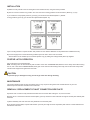
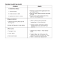
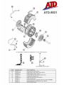
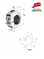
ATD-8031
3/8” Air Hose Reel
INSTRUCTION MANUAL
INTRODUCTION
Thank you for purchasing your ATD-8031 3/8” Air hose reel.
This hose reel is a breakthrough in industrial quality hose reel design, performance, durability, versatility and cost.
The efficiency, safety and convenience benefits of auto rewind hose reels are now available for most situations where a hose is
required.
Manufactured from the highest quality weather resistant materials, the tough high – impact polypropylene is U.V. stabilized,
designed for all purpose corrosion-free durability. The rewind mechanism is lubricated and sealed for trouble-free operation.
This retractable hose reel promotes a neat and tidy good looking work area, reducing the possibility of accidents, and
improves the work environment. Safety is enhanced by low recoil tension even with the hose fully extended.
With your appropriate care you will be assured of continuous safe, efficient and reliable product operation.
GENERAL INFORMATION
This manual assists you in operating and maintaining your new Retractable hose reel. The information contained will help you
ensure many years of dependable performance and trouble free operation.
Please take a few moments to read through this manual before installing and operating your Retractable reel. If you
experience problems with the product; refer to the procedures contained within this instruction manual. If you require further
assistance please contact your local distributor.
IMPORTANT INFORMATION
PLEASE READ THIS SAFETY INFORMATION CAREFULLY BEFORE USE.
Please read and retain this instruction manual to assist you in the operation and maintenance of this quality product.
Your safety is important to us. Please read, understand and follow all safety instructions listed below. Some of these instructions
alert you to the potential for personal injury. “Cautions” listed throughout the manual advises of potential practices or procedures
which may cause damage to your equipment.
Make sure all operators have access to adequate instructions about safe operating and maintenance procedures.
This hose reel contains a pre-tensioned spring inside the drum assembly. For safety reasons the drum assembly is a non-repairable
item. DO NOT under any circumstances try to open the drum assembly. A new drum assembly will be required if the spring is
damaged.
•
DO NOT exceed the maximum working pressure stated on the product label.
•
The maximum installation height is 4.5 meters (15ft) above the ground.
•
The maximum weight of hose end tools is 2kg (4lb).
•
This reel contains a positive latching mechanism, which enables the reel to be mounted in any position.
INSTALLATION
a) Attach the carry handle to the reel casing above the reel/hose mouth, using the screws provided.
b) The reel can be mounted in any position. The most common mounting positions are shown below. (Refer Fig 1,2,3,4)
If you choose the most popular positions (1) and (2) you should use the standard (8031-17) bracket.
If using positions (3) and (4) you will need the optional bracket (8031-16).
c) Fix mounting bracket in required location and position reel onto bracket. Brackets can be padlocked for additional security.
d) Connect supply hose to reel inlet allowing sufficient space for reel to swivel 180° on bracket.
Swivel rotation can be avoided (in the overhead position only) by adding the locking bracket (8031-18) supplied.
POSITIVE LATCH OPERATION
Pull out the hose to the required length.
Note: A clicking noise can be heard every half revolution of the drum. To latch the reel, allow the reel to slowly retract after hearing
the 1st, 2nd or 3rd click. To unlatch the reel, slowly pull out the hose until the clicking noise stops, then let the hose slowly retract
until the hose stopper rests against the reel mouth.
CAUTION
To prevent injury or damage occurring, do not let go of the hose during rewinding.
MAINTENANCE
This section details the step-by-step procedures that you may require for the general use and maintenance of your reel.
Please keep this instruction manual for future reference.
REMOVAL / REPLACEMENT OF INLET CONNECTION SIDE PLATE
a) Pull the hose out until it is fully extended and allow the hose to latch after hearing the 1st, 2nd or 3rd click.
b) Place reel on a clean bench with the inlet side plate (1) face up. Remove screw located at the edge of the inlet plate. Rotate plate
clockwise.
c) Swivel assembly and hose will come away attached to the inlet side plate.
d) To replace inlet side plate, suspend reel between your body and edge of bench. Reposition plate and turn counterclockwise and
relocate the side screw.
SPRING TENSION AND LATCH SIDE PLATE REMOVAL
a) Place reel on a clean bench with latching plate (9) face up.
b) Release spring tension by opening tension plate (8) and place handle of a pair of pliers in the exposed slots. Grip the pliers firmly
and remove the two screws holding the tension plate (8) and carefully allow the tension plate to slowly unwind counter-clockwise.
c) Remove screw holding tension plate and remove tension plate. Remove screw located at the edge of the latching plate. Turn
latching plate clockwise and remove, this will expose the latching cup assembly.
d) To replace latching plate, suspend reel between your body and edge of the bench. Reposition the plate and turn counterclockwise. Relocate side screws, replace tension plate and fixing screw.
e) Reload spring tension by using the same tool (as in step B) and wind tension plate clockwise until hose stopper is firmly against
the reel mouth, some resistance will be felt. Then, add approximately six (6) complete 360° tension turns. Hold the tension plate in
this position, align dimples on tension plate latching side plate and replace the two screws. Close tension plate and cover.
SWIVEL SEAL REPLACEMENT
a) Place reel on a clean bench with inlet side plate (1) face up
b) Remove the inlet side plate (Refer Removal/Replacement Inlet Connection Side Plate).
c) Remove circlip (4) from end of swivel shaft assembly (2) and slide the inlet shaft from the swivel body (3).
d) Carefully remove the existing O-Rings by lifting O-Rings out from grooves using a small screwdriver. With O-Rings extended, cut
through the O-Ring onto the screwdriver face. Be careful you do not score O-Ring grooves.
CAUTION
Do not damage or score inlet shaft surface when removing or cutting O-Ring.
e) Before fitting new O-Rings ensure that both inlet shaft and swivel are thoroughly wiped clean.
SWIVEL RE-ASSEMBLY
a) Slide inlet shaft back into the swivel body and replace circlip.
b) Slide inlet shaft back into the drum assembly (5), pushing complete unit home.
c) Replace inlet side plate. (Refer to “Removal/Replacement of Inlet Connection Side Plate”)
HOSE REPLACEMENT
a) Pull the hose out until it is fully extended and allow the hose to latch after hearing the 1st, 2nd or 3rd click.
b) Remove the inlet side plate (1) (Refer “Removal /Replacement of Inlet Connection Side Plate”). The swivel shaft assembly (2) will
come away attached to the inlet side plate.
c) Remove hose from swivel body (3). Remove remaining old hose from the mouth of the reel.
d) Use only recommended length and type of replacement hose.
e) Feed the new hose through top of reel mouth and into opening on reel drum which gives access to the swivel compartment.
Replace and secure the internal hose stopper 5” from the end of hose assembly. Reconnect hose.
f) Replace inlet side plate (1) (Refer “Removal/Replacement of Inlet Connection Side Plate”).
g) Place the reel in a vertical position and while holding the reel slowly pull the hose out until clicking noise stops. The hose will now
rewind. Carefully guide the hose onto the drum.
h) If the replacement hose is the same length as the old hose no tension adjustment is necessary. If tension adjustment is required
follow the ‘Spring Tension’ procedure (Refer to “Spring Tensioning and Latch Side Plate Removal)
CAUTION
Test reel for leaks prior to any further use.
TROUBLE SHOOTING GUIDE