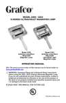
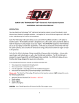
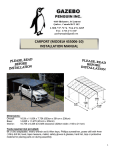
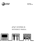
1
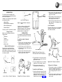
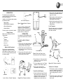
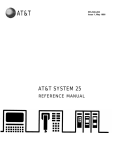
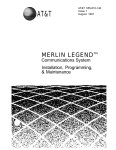
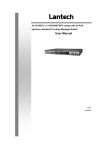
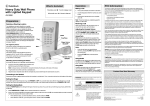
AT&T
Warranty
All terms and conditions specified in your
agreement with AT&T apply.
Federal Communications Commission
Registration Information
Statement (Part 68)
The following information is applicable only
to equipment connected directly to the
telephone network and not to connection of
stations behind terminal systems.
The following equipment is registered with
the Federal Communications Commission
(FCC) in accordance with Part 68 of its
Rules:
Apparatus
Code*
Standard Network
Interface Jack(s)
500ADM
500BDM
500MM
500SM
503CM
514BMW
514CM
554BMPA
2223C
2224C
2500MM
2500MMG
2500MMGB
2500MMGF
2500SM
2503CM
2504BM
2504CM
2514BM
2514CM
2554BMPA
2554BMPB
RJ11C, RJ14C, RJ36X
RJ11C, RJ14C, RJ36X
RJ11C, RJ14C,RJ36X
RJ11C, RJ14C, RJ36X
RJ11C, RJ14C, RJ36X
RJ11C, RJ14C, RJ36X
RJ11C, RJ14C, RJ36X
RJ11W, RJ14W
RJ11C, RJ17C
RJ11W, RJ17C
RJ11C, RJ14C, RJ36X
RJ11C, RJ14C, RJ36X
RJ11C, RJ14C, RJ36X
RJ11C, RJ14C, RJ36X
RJ11C, RJ14C, RJ36X
RJ11C, RJ14C, RJ36X
RJ11C, RJ14C, RJ36X
RJ11C, RJ14C, RJ36X
RJ11C, RJ14C, RJ36X
RJ11C, RJ14C, RJ36X
RJ11C, RJ14W
RJ11W, RJ14W
* The apparatus code is stamped on the
bottom of the set.
In compliance with the rules, you should
be aware of the following:
1. Connection of this equipment to the
telephone network must be through one
of the standard network interface jacks
listed above. These may be ordered
from the local telephone company or
through AT&T Information Systems as
your authorized agent.
2. Customers connecting equipment to the
telephone network shall, upon request of
the local telephone company, provide
the following information:
●
The telephone number assigned to
the line used with this telephone.
The Registration Number and the
Ringer Equivalence Number (REN)
from the Registration label on the
bottom of the telephone.
Note: This equipment is registered to be
used on telephone lines with “A”
type ringing frequencies. However,
some telephone companies use a
variety of other ringing
frequencies, e.g., “B”, “C”. As a
result, this telephone may or may
not ring properly when connected
to a telephone line that provides
other than “A” type ringing.
Consult your AT&T Information
Systems representative for advice.
●
3. Notify the local telephone company
when this equipment is permanently
disconnected from the line.
4. If trouble is experienced, the telephone
set should be unplugged from the
network interface to determine if the
telephone set or the telephone line is
the trouble source. If your telephone set
is determined to be malfunctioning, it
should not be reconnected until repairs
are made.
5. Repairs to this equipment, other than
routine repairs, can be made only by
AT&T Technologies or its authorized
agents.
6. If a telephone set causes harm to the
telephone network, the local telephone
company may temporarily discontinue
your service and, if possible, notify you
in advance. If advance notice is not
practical, you will be notified as soon as
possible. You will be given the
opportunity to correct the problem and
informed of your right to file a complaint
with the FCC.
The local telephone company may make
changes in its facilities, equipment,
operation, or procedures that could
affect the proper functioning of your
equipment. If they do, you will be given
adequate notice in writing to allow you
an opportunity to maintain uninterrupted
telephone service.
Hearing Aid Compatibility
These telephones are compatible with
inductively coupled hearing aids as
prescribed by the Federal Communications Commission (FCC), except for
Models 223C and 224C.
CAUTION
The following safety information is
important to you. All of the telephones
listed, with the exception of message
waiting models, are NOT FOR
RESIDENTIAL USE. They are sold for
BUSINESS SYSTEMS APPLICATIONS
ONLY. Use in a residential environment
could result in an electrical short circuit
when the telephone wiring is set up to
provide other applications, e.g.
appliance control, power transformers
lighting telephones, etc. The AC power
used in these applications may create a
safety hazard since lifting the handset
from the telephone base places a direct
short circuit across the telephone
wiring.
SINGLE LINE
BUSINESS
TELEPHONES
DESK, WALL AND
TRIMLINE® MODELS
ISSUE 3
APRIL 1986
403683022
999-500-270-IS
950-270-IS
AT&T
INTRODUCTION
JACK
OPENING
This booklet contains installation and
removal instructions for standard modular
desk or wall telephones.
Installation of the following options requires
a professional installer.
●
Adjunct Dialer
●
SPOKESMAN® Loudspeaker
●
External Speakerphone
●
Headset Adapter
Contact your place of purchase for details.
Package Content
Make sure your package contains the
following items:
●
Telephone
●
Handset
●
Handset cord
●
Line cord
●
Number card
Modular Outlet Requirement
You must have a standard modular
telephone jack, such as one of those
shown below, to install your phone. If you
have one of these jacks already mounted,
no tools are needed.
RINGER
VOLUME
CONTROL
Jack For Wall Telephone
2. Plug one end of the coiled handset cord
into the jack in the handset. Push the
plug in until it clicks.
3. Plug the other end of the cord into the
jack in the bottom of the wall base.
Push the plug in until it clicks.
4. Adjust the ringer volume switch on the
upper right side of the telephone to the
desired setting.
Figure 1. Standard Modular Telephone
Jacks
For All Telephones
If you do not have a standard modular
telephone jack, contact your local
telephone company or AT&T Information
Systems for details on converting your
present outlet to a modular jack.
Place the number card on your telephone
following the instructions on the back of
the number card label.
HANDSET
INSTALLATION
Your telephone is fully assembled except
for the coiled handset cord and clear line
cord.
RINGER
VOLUME
CONTROL
BASE
RINGER
VOLUME
CONTROL
To Install Your Desk Or Trimline®
Telephone
1. Plug one end of the coiled handset cord
into the opening in the handset. Push
the plug in until it clicks. (Figure 2)
2. Plug the other end of the cord into the
side opening in the base. Push the plug
in until it clicks.
3. Plug one end of the clear line cord into
the jack in the base of the telephone.
Push the plug in until it clicks.
RIVETS
JACK
COILED HANDSET CORD
Figure 3. Setting the Ringer Volume
Control (Desk and Trimline Telephones)
WALL
PHONE
PLUG
COILED HANDSET
CORD JACK
COILED
HANDSET
CORD
HANDSET
4. Plug the other end of the cord into the
telephone jack in your office. Push the
plug in until it clicks.
JACK OPENING
OR
JACK
JACK
JACK
HANDSET
JACK OPENING
Jacks for Desk or Trimline® Telephones
CLEAR
LINE
CORD
COILED
HANDSET
CORD
Figure 2. Desk Telephone Installation
JACK
5. Turn your telephone over or for Trimline
telephones, lift the handset. (Figure 3)
Figure 4. Wall Telephone Installation
6. Set the ringer volume switch or
thumbwheel to the setting you want.
To Remove Your Telephone
To Install Your Wall Telephone
1. Align the wall phone plug with the jack,
then line up the hole in the back of the
telephone set with the rivets on the wall
outlet plate. Push in and slide the
telephone down into place. (Figure 4)
1. To disconnect or remove your telephone
reverse the installation procedures. To
remove any modular plug, squeeze the
clip of the plug and pull it out of the
jack.
2. To disconnect a wall set, slide the set up
to lift it off the rivets and pull it away
from the wall.
AT&T
Warranty
All terms and conditions specified in your
agreement with AT&T apply.
Federal Communications Commission
Registration Information
Statement (Part 68)
The following information is applicable only
to equipment connected directly to the
telephone network and not to connection of
stations behind terminal systems.
The following equipment is registered with
the Federal Communications Commission
(FCC) in accordance with Part 68 of its
Rules:
Apparatus
Code*
Standard Network
Interface Jack(s)
500ADM
500BDM
500MM
500SM
503CM
514BMW
514CM
554BMPA
2223C
2224C
2500MM
2500MMG
2500MMGB
2500MMGF
2500SM
2503CM
2504BM
2504CM
2514BM
2514CM
2554BMPA
2554BMPB
RJ11C, RJ14C, RJ36X
RJ11C, RJ14C, RJ36X
RJ11C, RJ14C,RJ36X
RJ11C, RJ14C, RJ36X
RJ11C, RJ14C, RJ36X
RJ11C, RJ14C, RJ36X
RJ11C, RJ14C, RJ36X
RJ11W, RJ14W
RJ11C, RJ17C
RJ11W, RJ17C
RJ11C, RJ14C, RJ36X
RJ11C, RJ14C, RJ36X
RJ11C, RJ14C, RJ36X
RJ11C, RJ14C, RJ36X
RJ11C, RJ14C, RJ36X
RJ11C, RJ14C, RJ36X
RJ11C, RJ14C, RJ36X
RJ11C, RJ14C, RJ36X
RJ11C, RJ14C, RJ36X
RJ11C, RJ14C, RJ36X
RJ11C, RJ14W
RJ11W, RJ14W
* The apparatus code is stamped on the
bottom of the set.
In compliance with the rules, you should
be aware of the following:
1. Connection of this equipment to the
telephone network must be through one
of the standard network interface jacks
listed above. These may be ordered
from the local telephone company or
through AT&T Information Systems as
your authorized agent.
2. Customers connecting equipment to the
telephone network shall, upon request of
the local telephone company, provide
the following information:
●
The telephone number assigned to
the line used with this telephone.
The Registration Number and the
Ringer Equivalence Number (REN)
from the Registration label on the
bottom of the telephone.
Note: This equipment is registered to be
used on telephone lines with “A”
type ringing frequencies. However,
some telephone companies use a
variety of other ringing
frequencies, e.g., “B”, “C”. As a
result, this telephone may or may
not ring properly when connected
to a telephone line that provides
other than “A” type ringing.
Consult your AT&T Information
Systems representative for advice.
●
3. Notify the local telephone company
when this equipment is permanently
disconnected from the line.
4. If trouble is experienced, the telephone
set should be unplugged from the
network interface to determine if the
telephone set or the telephone line is
the trouble source. If your telephone set
is determined to be malfunctioning, it
should not be reconnected until repairs
are made.
5. Repairs to this equipment, other than
routine repairs, can be made only by
AT&T Technologies or its authorized
agents.
6. If a telephone set causes harm to the
telephone network, the local telephone
company may temporarily discontinue
your service and, if possible, notify you
in advance. If advance notice is not
practical, you will be notified as soon as
possible. You will be given the
opportunity to correct the problem and
informed of your right to file a complaint
with the FCC.
The local telephone company may make
changes in its facilities, equipment,
operation, or procedures that could
affect the proper functioning of your
equipment. If they do, you will be given
adequate notice in writing to allow you
an opportunity to maintain uninterrupted
telephone service.
Hearing Aid Compatibility
These telephones are compatible with
inductively coupled hearing aids as
prescribed by the Federal Communications Commission (FCC), except for
Models 223C and 224C.
CAUTION
The following safety information is
important to you. All of the telephones
listed, with the exception of message
waiting models, are NOT FOR
RESIDENTIAL USE. They are sold for
BUSINESS SYSTEMS APPLICATIONS
ONLY. Use in a residential environment
could result in an electrical short circuit
when the telephone wiring is set up to
provide other applications, e.g.
appliance control, power transformers
lighting telephones, etc. The AC power
used in these applications may create a
safety hazard since lifting the handset
from the telephone base places a direct
short circuit across the telephone
wiring.
SINGLE LINE
BUSINESS
TELEPHONES
DESK, WALL AND
TRIMLINE® MODELS
ISSUE 3
APRIL 1986
403683022
999-500-270-IS
950-270-IS
AT&T
Warranty
All terms and conditions specified in your
agreement with AT&T apply.
Federal Communications Commission
Registration Information
Statement (Part 68)
The following information is applicable only
to equipment connected directly to the
telephone network and not to connection of
stations behind terminal systems.
The following equipment is registered with
the Federal Communications Commission
(FCC) in accordance with Part 68 of its
Rules:
Apparatus
Code*
Standard Network
Interface Jack(s)
500ADM
500BDM
500MM
500SM
503CM
514BMW
514CM
554BMPA
2223C
2224C
2500MM
2500MMG
2500MMGB
2500MMGF
2500SM
2503CM
2504BM
2504CM
2514BM
2514CM
2554BMPA
2554BMPB
RJ11C, RJ14C, RJ36X
RJ11C, RJ14C, RJ36X
RJ11C, RJ14C,RJ36X
RJ11C, RJ14C, RJ36X
RJ11C, RJ14C, RJ36X
RJ11C, RJ14C, RJ36X
RJ11C, RJ14C, RJ36X
RJ11W, RJ14W
RJ11C, RJ17C
RJ11W, RJ17C
RJ11C, RJ14C, RJ36X
RJ11C, RJ14C, RJ36X
RJ11C, RJ14C, RJ36X
RJ11C, RJ14C, RJ36X
RJ11C, RJ14C, RJ36X
RJ11C, RJ14C, RJ36X
RJ11C, RJ14C, RJ36X
RJ11C, RJ14C, RJ36X
RJ11C, RJ14C, RJ36X
RJ11C, RJ14C, RJ36X
RJ11C, RJ14W
RJ11W, RJ14W
* The apparatus code is stamped on the
bottom of the set.
In compliance with the rules, you should
be aware of the following:
1. Connection of this equipment to the
telephone network must be through one
of the standard network interface jacks
listed above. These may be ordered
from the local telephone company or
through AT&T Information Systems as
your authorized agent.
2. Customers connecting equipment to the
telephone network shall, upon request of
the local telephone company, provide
the following information:
●
The telephone number assigned to
the line used with this telephone.
The Registration Number and the
Ringer Equivalence Number (REN)
from the Registration label on the
bottom of the telephone.
Note: This equipment is registered to be
used on telephone lines with “A”
type ringing frequencies. However,
some telephone companies use a
variety of other ringing
frequencies, e.g., “B”, “C”. As a
result, this telephone may or may
not ring properly when connected
to a telephone line that provides
other than “A” type ringing.
Consult your AT&T Information
Systems representative for advice.
●
3. Notify the local telephone company
when this equipment is permanently
disconnected from the line.
4. If trouble is experienced, the telephone
set should be unplugged from the
network interface to determine if the
telephone set or the telephone line is
the trouble source. If your telephone set
is determined to be malfunctioning, it
should not be reconnected until repairs
are made.
5. Repairs to this equipment, other than
routine repairs, can be made only by
AT&T Technologies or its authorized
agents.
6. If a telephone set causes harm to the
telephone network, the local telephone
company may temporarily discontinue
your service and, if possible, notify you
in advance. If advance notice is not
practical, you will be notified as soon as
possible. You will be given the
opportunity to correct the problem and
informed of your right to file a complaint
with the FCC.
The local telephone company may make
changes in its facilities, equipment,
operation, or procedures that could
affect the proper functioning of your
equipment. If they do, you will be given
adequate notice in writing to allow you
an opportunity to maintain uninterrupted
telephone service.
Hearing Aid Compatibility
These telephones are compatible with
inductively coupled hearing aids as
prescribed by the Federal Communications Commission (FCC), except for
Models 223C and 224C.
CAUTION
The following safety information is
important to you. All of the telephones
listed, with the exception of message
waiting models, are NOT FOR
RESIDENTIAL USE. They are sold for
BUSINESS SYSTEMS APPLICATIONS
ONLY. Use in a residential environment
could result in an electrical short circuit
when the telephone wiring is set up to
provide other applications, e.g.
appliance control, power transformers
lighting telephones, etc. The AC power
used in these applications may create a
safety hazard since lifting the handset
from the telephone base places a direct
short circuit across the telephone
wiring.
SINGLE LINE
BUSINESS
TELEPHONES
DESK, WALL AND
TRIMLINE® MODELS
ISSUE 3
APRIL 1986
403683022
999-500-270-IS
950-270-IS