1
AT&T
555-500-200
Issue 1, May 1986
AT&T SYSTEM 25
REFERENCE MANUAL
©1986 AT&T
All Rights Reserved
Printed in USA
TO ORDER COPIES OF THIS DOCUMENT REFER TO DOCUMENT NUMBER 555-500-200.
Contact: Your AT&T Information Systems Account Team or
Call: 800-432-6600, Monday to Friday between 7:30 am
and 6:00 EST, or
Write: AT&T Customer Information Center
2855 North Franklin Road
PO. Box 19901
Indianapolis, Indiana 46219
FCC NOTIFICATION AND REPAIR INFORMATION
AT&T SYSTEM 25
.
This telephone equipment is registered with the Federal Communications Commission (FCC)
in accordance with Part 68 of it’s Rules. In compliance with the Rules, be advised of the
following:
MEANS OF CONNECTION
Connection of this telephone equipment to the nation-wide telecommunications network shall
be through a standard network interface jack USOC RJ21X. Connection to private line
network channels requires jack USOC RJ2GX for tie lines or jack USOC RJ21X for offpremises station lines. These can be ordered from your Telephone Company.
NOTIFICATION TO THE TELEPHONE COMPANY
If the system is to be connected to off-premises stations, you must notify the telephone
company of the OPS class of service, 0L13C, and the service order code, 9. OF.
Upon the request of the telephone company, you shall inform them of the following
- The Public Switched Network “ lines” (that is, your phone number) and the Private
“ lines” to which you will connect the telephone equipment.
- The telephone equipment’s “ registration number” and “ ringer equivalence number”
(REN) from the label on the equipment.
-
For Private Line Connections, provide the facility interface code; TL31M for tie lines.
You must also specify the service order code, 9. OF.
- The quantities and USOC numbers of the jacks required.
-
For each jack, provide the sequence in which lines are to be connected; the type lines
and the facility interface code and the ringer equivalence number by position when
applicable.
This telephone equipment should not be used on coin telephone lines. Connection to party
line service is subject to state tariffs.
REPAIR INSTRUCTIONS
If you experience trouble with this telephone equipment, contact the AT&T Business
Customer Service Center on 1-800-242-2121. The Telephone Company may ask that you
disconnect this equipment from the network until the problem has been corrected or until
you are sure that this equipment is not malfunctioning.
RIGHTS OF THE TELEPHONE COMPANY
If your telephone equipment causes harm to the telephone network, the Telephone Company
may discontinue your service temporarily. If possible, they will notify you in advance. But
if advance notice isn’t practical, you will be notified as soon as possible. You will be
informed of your right to file a complaint with the FCC.
Your Telephone Company may make changes in it’s facilities, equipment, operations or
procedures that could affect the proper functioning of your equipment. If they do, you will
be notified in advance to give you an opportunity to maintain uninterrupted telephone
service.
HEARING AID COMPATIBILITY
The voice terminals described in this manual are compatible with inductively coupled
hearing aids as prescribed by the FCC.
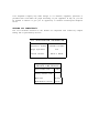
I FCC
REGISTRATION INFORMATION
Registration Number
AS593M-71565-MF-E
0.5A
Ringer Equivalence
Network Interface
RJ21X or RJ2GX
PRIVATE LINE SERVICE
Service Order Code
I
9.0F
Facility Interface Code
●
Tie Lines
TL31M
●
Off-Premises Stations
0L13C
FCC WARNING STATEMENT
Federal Communications Commission (FCC) Rules require that you be notified of the
following:
●
●
●
This equipment generates, uses, and can radiate radio frequency energy and, if
not installed and used in accordance with the instruction manual, may cause
interference to radio communications.
It has been tested and found to comply with the limits for a Class A computing
device pursuant to Subpart J of Part 15 of FCC Rules, which are designed to
provide reasonable protection against such interference when operated in a
commercial environment.
Operation of this equipment in a residential area is likely to cause interference in
which case the user at his or her own expense will be required to take whatever
measures may be required to correct the interference.
The AT&T System 25 cabinets are not user serviceable.
Some voltages inside the cabinets are hazardous. This
equipment is to be serviced only by qualified technicians.
CONTENTS
Page
1-1
1. OVERVIEW
Organization
l-l
System 25 Overview
1-2
Call Handling Capabilities
1-3
Safety
1-3
System Configuration
1-3
2-1
2. FEATURES AND SERVICES
INTRODUCTION
2-1
ACCOUNT CODE ENTRY
2-6
ATTENDANT CALL TRANSFER
2-8
ATTENDANT CAMP-ON
2-10
ATTENDANT
CANCEL
2-11
ATTENDANT CONSOLE
2-12
Dual Attendant Console Operation
2-13
ATTENDANT DIRECT EXTENSION SELECTION
2-15
ATTENDANT MESSAGE WAITING
2-17
ATTENDANT POSITION BUSY
2-18
ATTENDANT RELEASE
2-20
ATTENDANT RETURN COVERAGE ON BUSY
2-21
ATTENDANT RETURN COVERAGE ON DON’T ANSWER
2-22
ATTENDANT SPLITTING ONE-WAY AUTOMATIC
2-23
ATTENDANT SYSTEM ALARM INDICATION
2-24
AUTOMATIC
2-25
INTERCOM
AUTOMATIC ROUTE SELECTION (ARS)
2-27
CALL ACCOUNTING SYSTEM (CAS)
2-35
CALL
COVERAGE–GROUP
2-38
CALL
COVERAGE–INDIVIDUAL
2-41
CALL
FOLLOWING
2-43
(FORWARDING)
C A L L
P A R K
2-45
CALL
PICKUP
2-47
CALL PROGRESS TONES
2-49
CALLING RESTRICTIONS
2-50
Outward
Toll
2-50
Restriction:
2-50
Restriction:
-i-
Facility
A R S
Access
Restriction:
2-50
R e s t r i c t i o n :
COMMAND MODE AND DATA TERMINAL DIALING
Data
Terminal
2-50
Dialing
2-52
2-54
CONFERENCE
2-58
CONFERENCE DROP
2-60
DATA CALLS AND SERVICES
2-61
Data Endpoints
2-61
Data Endpoint States
2-63
Data Call Processing Modes
2-64
Connecting Configurations
2-65
Controlling Features
2-65
DIAL PLAN
2-66
DICTATION SYSTEM ACCESS
2-68
DIRECT GROUP CALLING (DGC)
2-69
DIRECT GROUP CALLING DELAY ANNOUNCEMENT
2-71
DIRECT INWARD DIALING (DID)
2-72
DIRECT STATION SELECTION (DSS)
2-74
DISTINCTIVE RINGING
2-76
Abbreviated Alerting
2-76
END-TO-END SIGNALING
2-77
EXCLUSION
2-78
EXTENDED STATIONS
2-79
EXTERNAL ALERTS
2-80
HANDS FREE ANSWER ON INTERCOM (HFAI)
2-81
HOLD
2-83
HOLD RELEASE ON ABANDON
2-84
INTERCEPT TREATMENT WITH REORDER TONES
2-85
INTERDIGIT TIMEOUTS
2-86
LINE SELECTION
2-87
LINE STATUS AND I-USE INDICATIONS
2-89
MANUAL SIGNALING
2-91
MESSAGING SERVICES
2-92
Attendant Message Waiting:
2-92
Call Coverage Message Waiting:
2-92
Station-To-Station Message Waiting:
2-93
2-94
MODEM POOLING
-ii-
MUSIC-ON-HOLD OR DELAYED ACCESS
2-96
NIGHT SERVICE.
2-97
NIGHT SERVICE DELAY ANNOUNCEMENTS
2-100
OFF-PREMISES STATIONS (OPS)
2-101
ONE-BUTTON-TRANSFER TO DATA
2-102
OUT-OF-BUILDING STATIONS
2-104
PAGING SYSTEM ACCESS
2-105
PAUSE
2-107
PERSONAL DIAL CODE (PDC)
2-108
PERSONAL LINES
2-111
POOLED FACILITY - BUTTON ACCESS
2-113
POOLED FACILITY - DIAL ACCESS
2-115
POWER FAILURE TRANSFER (PFT)
2-116
PROGRAM
2-118
RECALL
2-120
REMOTE ADMINISTRATION INTERFACE
2-121
REPERTORY DIALING
2-122
SPEAKER
2-123
SPEAKERPHONE
ADJUNCT
SPEED DIALING
2-124
2-125
System Speed Dialing:
2-125
Personal Speed Dialing:
2-125
STATION
2-127
HUNTING
STATION MESSAGE DETAIL RECORDING (SMDR)
Call
2-129
2-129
Accountability:
STATION-TO-STATION MESSAGE WAITING
2-136
T E S T
2-137
TIE TRUNKS
2-138
TOUCH-TONE AND DIAL PULSE SERVICES
2-139
TRANSFER
2-140
TRUNK GROUPS
2-142
TRUNK-TO-TRUNK TRANSFER
2-145
3. FUNCTIONAL DESCRIPTION
3-1
Common Control
3-2
Call Processor Circuit Pack (ZTN-82)
3-2
Memory Circuit Pack (ZTN-81B)
3-6
Switching
3-8
Network
-
iii-
3-8
TDM Bus
Port Circuits
3-12
Ground Start Trunk (ZTN-76)
3-18
Loop Start Trunk [ZTN-77)
3-20
Tip Ring Line (ZTN-78)
3-22
ATL Line(ZTN-79)
3-24
Data Line (TN-726)
3-26
MET Line (TN-735)
3-28
Analog Line (TN-742)
3-30
DID Trunk (TN-753)
3-32
Tie Trunk (TN-760B)
3-34
Auxiliary Trunk (TN-763)
3-38
System Resources
3-40
Service Circuit (ZTN-85)
3-40
Tone Detector (TN-748)
3-43
Pooled Modem (TN-758)
3-45
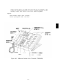
4. HARDWARE DESCRIPTION
4-1
System Cabinets (J58901A1)
4-1
Cabinet l (Control and Port Circuits)
4-5
Cabinet Address Plug
4-5
Cabinets 2 and 3 (Port Circuits)
4-5
4-8
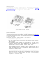
Circuit Packs
Required Circuit Packs
4-8
Optional Circuit Packs
4-8
Terminal
4-13
Equipment
Voice Terminals
4-14
Voice Terminal Adjuncts
4-38
Attendant Consoles
4-44
Asynchronous Data Units (ADUs)
4-47
4-50
Peripheral Equipment
System Administration Terminal
4-50
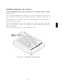
Digital Tape Unit
4-53
Station Message Detail Recording (SMDR) And Call Accounting System
(CAB)
4-54
4-55
Auxiliary Equipment
Dictation Equipment
4-55
External Alerting Equipment
4-56
-iv-
Music Source (Music-On-Hold)
4-56
Paging
4-56
Equipment
Recorded Delay Announcement Equipment
4-57
4-58
Connectivity
Trunk Access Equipment (TAE)
4-58
Station Interconnect Panel (SIP)
4-60
10B Emergency Transfer Unit (ETU)
4-63
Connectivity Figures
4-67
Voice Terminal And Adjunct Connections
4-67
Attendant Console Connections
4-67
Peripheral Equipment Connections
4-68
ADU Connections
4-68
Auxiliary Equipment Connections
4-68
4-95
Parts Information
5-1
5. SOFTWARE DESCRIPTION
General
5-1
Switched Services Software
5-1
Administrative Software
5-1
Maintenance Software
5-1
Memory Allocation
5-2
Real-Time Constraints
5-2
Software Partitioning
5-2
Step-By-Step Call Description
5-5
6. SYSTEM ADMINISTRATION
6-1
7. SYSTEM MAINTENANCE
7-1
System Errors And Alarms
7-1
Error Logs
7-2
Automatic Maintenance Tests
7-2
8-1
8. TECHNICAL SPECIFICATIONS
Hardware And Software Parameters
8-2
Unit Loads
8-5
Cable Distance Limitations
8-6
Tones
8-9
Indicator Lamp Signals
8-10
Port Specifications
8-11
Recommended Network Facilities (Trunks)
8-17
Analog Transmission Characteristics
8-18
-v-
9. ENVIRONMENTAL REQUIREMENTS
9-1
Floor Plans And Layouts
9-1
Table Top Space
9-4
Wall Space Requirements
9-4
Temperature and Humidity
9-4
Air Purity
9-5
Lighting
9-5
Electrical Noise (RFI)
9-5
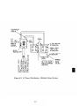
AC Power Requirements
9-6
Grounding
9-8
Lightning Protection
9-8
10-1
10. REFERENCE DOCUMENTATION
Administration Manual (555-500-500)
10-1
An Introduction to AT&T System 25 (555-500-021)
10-1
Implementation Manual (555-500-650)
10-2
Installation And Test Manual (555-500-100)
10-2
Maintenance Manual (555-500-105)
10-2
Planning Manual (555-500-600)
10-2
Reference Manual (555-500-200)
10-2
Terminal Operations Manual (555-500-710)
10-3
User Guides (700 Series)
10-3
11. GLOSSARY
11-1
12.INDEX
12-1
,
-vi-
LIST
OF
FIGURES
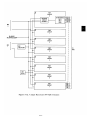
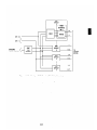
Figure 1-l
System 25 Block Diagram
Figure 2-1
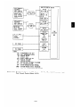
Automatic Route Selection Flow Chart (Sheet l of 2)
2-32
Figure 2-2
Automatic Route Selection Routing Pattern
2-34
Figure 2-3
Asynchronous Data Unit Interface Signals
2-62
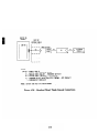
Figure 2-4
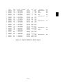
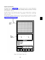
Typical SMDRCall Detail Report
2-133
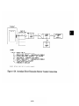
Figure 2-5
SMDR Call Record Format
2-134
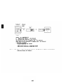
Figure 2-6
SMDR Call Record Header Format
2-135
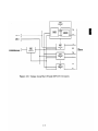
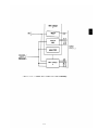
Figure 3-1
System 25 Digital Switch
3-1
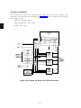
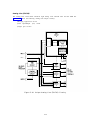
Figure 3-2
Call Processor (ZTN-82) Circuitry
3-3
Figure 3-3
Memory (ZTN-8113) Circuitry
3-7
Figure 3-4
TDM Bus Time Slot Generation (Not A Timing Diagram)
3-8
Figure 3-5
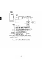
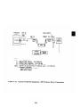
TDM Bus Diagram -
Figure 3-6
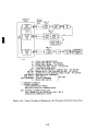
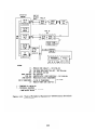
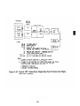
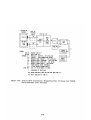
Equipment Connected To System 25 Via The Call Processor And Port
Circuit Packs (Sheet l of 3)
3-13
Figure 3-7
Port Circuit Pack Common Circuitry
3-17
Figure 3-8
Unique Ground Start Trunk (ZTN-76) Circuitry
3-19
Figure 3-9
Unique Loop Start Trunk (ZTN-77) Circuitry
3-21
Three
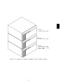
1-4
Cabinet
System
3-11
Figure 3-10 Unique Tip Ring Line (ZTN-78) Circuitry
3-22
Figure 3-11 U n i q u e A T L L i n e ( Z T N - 7 9 ) C i r c u i t r y
3-25
Figure 3-12 U n i q u e D a t a L i n e ( T N - 7 2 6 ) C i r c u i t r y
3-27
Figure 3-13 Unique MET Line (TN-735) Circuitry
3-29
Figure 3-14 Unique Analog Line (TN-742) Circuitry
3-30
Figure 3-15 Unique DID Trunk (TN-753) Circuitry
3-33
Figure 3-16 Unique Tie Trunk (TN-760B) Circuitry
3-35
Figure
3-37
3-17
Tie Trunk (TN-760B) Circuit Pack Option Switches
Figure 3-18 Unique Auxiliary Trunk (TN-763) Circuitry
3-39
Figure 3-19 Service Circuit (ZTN-85)
3-41
Figure 3-20 Tone Detector (TN-748) Circuit
3-44
Figure
3-21 Pooled Modem (TN-758) Circuit
3-46
Figure
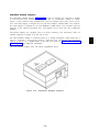
4-1 System 25 Cabinets (J58901A)–Three Cabinet System
4-3
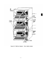
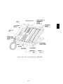
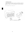
Figure 4-2 System Cabinet (J58901A)—Rear View
4-4
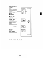
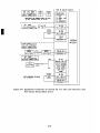
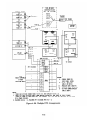
Figure 4-3 System Circuit Pack Configurations
4-6
Figure
4-4 Model 2500 Series (Analog) Voice Terminals
- vii -
4-16
4-17
Figure 4-5
Mode1
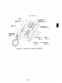
Figure 4-6
Five Button Voice Terminal (7302HOlC)
4-21
Figure 4-7
Ten Button Voice Terminal (7303HOlB)
4-23
Figure 4-8
34-Button Voice Terminal (7305HOlB)
4-25
Figure 4-9
34-Button Deluxe Voice Terminal (7305H02B)
4-27
7101A
(Analog)
Voice
Terminal
Figure 4-10 B I S V o i c e T e r m i n a l ( 7 3 0 5 H 0 3 B )
4-29
Figure 4-11 HFAI Voice Terminal (7309HOlA)
4-31
Figure 4-12 T e n B u t t o n M E T S e t ( 2 9 9 1 C 0 5 )
4-33
Figure 4-13 Ten Button MET With Built-In Speakerphone (2993C04)
4-35
Figure 4-14 T w e l v e B u t t o n M E T S e t ( 7 2 0 3 M )
4-37
Figure 4-15 5 0 0 A / 5 0 2 A H e a d s e t A d a p t e r s
4-39
Figure 4-16 4 A S p e a k e r p h o n e S y s t e m
4-40
Figure 4-17 S 1 0 1 A / S 1 0 2 A S p e a k e r p h o n e
4-41
Figure 4-18 Attendant Consoles
4-44
Figure 4-19 Model 23A1 Attendant Direct Extension Selector (DXS)
4-46
Figure 4-20 Asynchronous Data Unit (ADU)
4-48
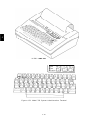
Figure 4-21 Model 703 System Administration Terminal
4-52
Figure 4-22 Model DC5 Digital Tape Unit
4-53
Figure 4-23 T r u n k A c c e s s E q u i p m e n t ( T A E ) C o n n e c t i o n s
4-59
Figure 4-24 617A Station Interconnect Panel
4-61
Figure 4-25 Typical SIP Connections
4-62
Figure 4-26 10B Emergency Transfer Unit (ETU)
4-64
Figure 4-27 Emergency Transfer Unit Connections
4-65
Figure 4-28 M u l t i p l e E T U A r r a n g e m e n t s
4-66
Figure 4-29 On-Premises Single-Line Voice Terminal Connections
4-69
Figure 4-30 Out-Of-Building Single-Line Voice Terminal Connections
4-70
Figure 4-31 Off-Premises Station Single-Line Voice Terminal Connections
4-71
Figure 4-32 On-Premises 7300H Series Multiline Voice Terminal
Connections
4-72
Figure 4-33 Out-Of-Building 7300H Series Multiline Voice Terminal
Connections
4-73
Figure 4-34
4-74
Figure 4-35 Typical Adjunct Connections For 7300H Series Multiline Voice
Terminals (Except 34-Button Deluxe Set)
4-75
Figure 4-36 Typical Adjunct Connections For 34-Button Deluxe Voice Terminal
(Includes Attendant Direct Trunk Console)
4-76
Figure 4-37 Typical Adjunct Connections For 12-Button MET Set
4-77
-Viii -
Figure 4-38 Attendant Direct Trunk Console Connections
4-78
Figure 4-39 Attendant Direct Extension Selector Console Connections
4-79
Figure 4-40 Typical Peripheral Equipment– On-Premises Direct Connections
(Sharing Same AC Outlet)
4-80
Figure 4-41 Typical Peripheral Equipment–On-Premises Direct Connections
(Greater Than 50 Feet From System Cabinet)
4-81
Figure 4-42 Typical Peripheral Equipment–On-Premises Switched
Connections
4-82
Figure 4-43 Typical Peripheral Equipment—Off-Premises Direct
Connections
4-83
Figure 4-44 Typical Peripheral Equipment–Off-Premises Switched
Connections
4-84
Figure 4-45 Typical ADU Connections– Supporting Data Terminal And Single-Line
Voice Terminal
4-85
Figure 4-46 Typical ADU Connections–Supporting Data Terminal And 7300H
Series Multiline Voice Terminal
4-86
Figure 4-47 Z 3 A 1 / 2 / 4 A D U L o c a l P o w e r C o n n e c t i o n s
4-87
Figure 4-48 Dictation System Connections (FCC Registered)
4-88
Figure 4-49 E x t e r n a l A l e r t C o n n e c t i o n s
4-89
Figure 4-50 Music-On-Hold Equipment Connections (FCC Registered)
4-90
Figure 4-51 Music-On-Hold Equipment Connections (Non-Registered)
4-91
Figure 4-52 Paging Equipment Connections—Using CO Trunk Ports (FCC
Registered)
4-92
Figure 4-53 Paging Equipment Connections— Using Auxiliary Trunk Ports (FCC
Registered Or Non-Registered)
4-93
Figure 4-54 Delay Announcement Equipment Connections (FCC
Registered)
4-94
Figure 5-1
System Software Partitioning
5-4
Figure 8-1
Single-Line Voice Terminal Allowable Cable Distances
8-6
Figure 8-2
Multiline Voice Terminal Allowable Cable Distances
8-7
Figure 8-3
Asynchronous Data Unit Allowable Cable Distances
8-8
Figure 9-1
Typical System 25 Equipment Area Floor Plan
9-2
Figure 9-2
Typical System 25 Equipment Area Elevation Plan
9-3
Figure 9-3
AC Power Distribution - Multiple Cabinet System
9-7
-ix-
LIST OF TABLES
TABLE 2-A System Features
2-3
TABLE 2-B Station Features
2-4
TABLE 2-C Attendant Features
2-5
TABLE 2-D D a t a F e a t u r e s
2-5
TABLE 2-E Permissible Data Port (TN-726) Options
2-53
TABLE 2-F Call Progress Messages for Data Terminal Dialing
2-56
TABLE 3-A T D M B U S T i m e S l o t s
3-1o
TABLE 3-B TN-760B Available Signaling Formats
3-36
TABLE 3-C TN-760B Tie Trunk Preferred Signaling Formats
3-36
TABLE 3-D S i g n a l i n g T y p e S u m m a r y
3-37
TABLE 4-A Total Port Circuit Packs Per System
4-7
TABLE 4-B S y s t e m C i r c u i t P a c k s
4-12
TABLE 4-C Supplemental Voice Terminal Power Supplies
4-43
TABLE 4-D Z3A Asynchronous Data Units (ADUs)
4-49
TABLE 8-A Central Office Trunk Recommendations
8-17
-X-
1. OVERVIEW
This manual provides general technical information on AT&T System 25 (System 25). It
includes a description of the system, its hardware and software, features and services,
environmental requirements, and technical specifications. This manual is intended to serve
as an overall technical reference for System 25.
Organization
The manual is divided into 12 Sections. The remaining Sections are as follows:
●
SECTION
2–FEATURES
AND
SERVICES
●
SECTION
3–FUNCTIONAL
●
SECTION
4–HARDWARE
●
SECTION
5–SOFTWARE
●
SECTION
6–SYSTEM ADMINISTRATION
●
SECTION
7–SYSTEM MAINTENANCE
●
SECTION
8–TECHNICAL SPECIFICATIONS
●
SECTION 9–ENVIRONMENTAL REQUIREMENTS
●
SECTION 10–REFERENCE DOCUMENTATION
●
SECTION
11–GLOSSARY
●
SECTION
12–INDEX
DESCRIPTION
DESCRIPTION
DESCRIPTION
1-1
System 25 Overview
S y s t e m 2 5 is an advanced digital switching system which integrates voice and data
communications. It not only provides the features of a state-of-the-art PBX, but goes a step
further by allowing digital data to be switched point-to-point without first being converted
to analog format. This capability can be used to set up connections between data terminals,
word processors, personal computers, and host computers.
System 25 uses intelligent port circuits equipped with distributed network processor
elements to provide (essentially) nonblocking voice and data switching.
Voice communications features combine traditional telephone features, such as Call Transfer
and Hold, with advanced features, such as Individual and Group Call Coverage, Hands-FreeAnswer On Intercom, and Speed Dialing (See “Features and Services’’ -Section 2.)
Data communications features provide switched data connections supporting transmission of
voice or data over Premises Distribution System wiring. Connections can be made between
two digital data modules (asynchronous data units), two analog modems, or between an
analog modem and a digital data module.
The system provides an RS-232C interface for full duplex, asynchronous, transmission of
data up to 19,200 bps, and a 212-compatible modem pool conversion resource.
System 25 supports the following:
●
Trunk and Network Facilities–Dual Tone Multifrequency (DTMF) and Dial
Signaling on incoming and outgoing trunks (dial pulse only on DID trunks).
Pulse
— Loop Start (LS)
— Ground Start (GS)–(Strongly preferred Over Loop start)
— Tie Trunks (Type I and Type I Compatible E&M, Type V Simplex)
– Direct Inward Dialing (DID)
●
Voice
Terminals–Single-Line
●
Data
Facilities
Touch-Tone,
MET,
and
MERLIN®
— Digital Data End Points—RS-232C Interfaces via Asynchronous Data Units
(ADUs)
— Analog Data End Points—Tip/Ring-Type Modem Interfaces,
●
Networking
Capability
— Tie Trunks
— Endpoint in Electronic Tandem Network–(Tributary only, not Satellite)
— Endpoint of Enhanced Private Switched Communications Services (EPSCS)
— Endpoint of Tandem Tie Trunk Network (TTTN)
— Endpoint of Common Control Switching Arrangement (CCSA).
1-2
Call Handling Capabilities
System 25 can be arranged as a stand-alone system or can be part of a private network. The
system provides 256 ports to support the following:
●
115 simultaneous two-party conversations
●
Traffic Handling–4140 CCS/Hour (Trunking Limited)
●
Busy Hour Call Capacity–2500 calls (DTMF Register Limited)
●
Up to 104 trunk ports including Central Office (CO), DID, Tie, Foreign Exchange
(FX), and Wide Area Telecommunications Service (WATS), and 800 Service.
●
An Auxiliary Trunk interface for paging and dictation systems
●
Up to 240 ports that support a combination of the following:
— Up to 200 ports for voice terminals and auxiliary equipment.
— Up to 104 data ports providing RS-232C connections to data terminals,
personal or multiport computers.
Refer to Hardware and Software Parameters as provided in “Technical Specifications”
(Section 8) for detailed specifications.
Safety
System 25 meets all requirements found in Underwriters Laboratories Standard for Safety,
Office Appliances and Business Equipment (UL114).
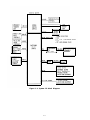
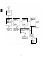
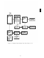
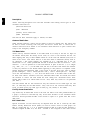
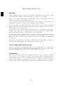
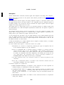
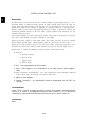
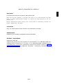
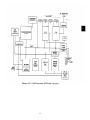
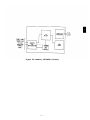
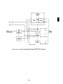
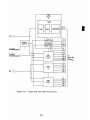
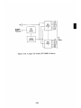
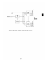
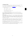
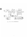
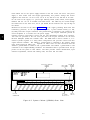
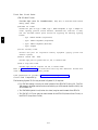
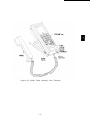
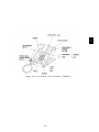
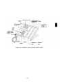
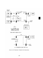
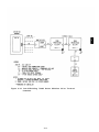
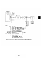
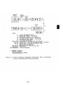
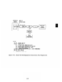
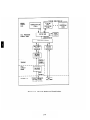
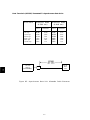
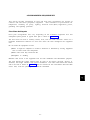
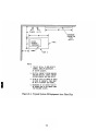
System Configuration
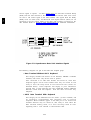
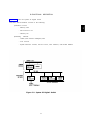
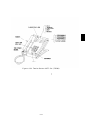
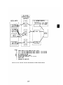
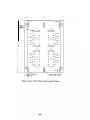
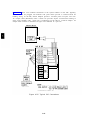
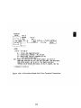
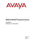
Figure 1-1 shows a typical equipment configuration
1-3
1
J
Figure 1-1. System 25 Block Diagram
1-4
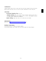
2. FEATURES AND SERVICES
INTRODUCTION
This section describes the System Features, Station Features, Attendant Features, and Data
Features of AT&T System 25. The feature descriptions are arranged in alphabetical order,
regardless of the feature group to which they belong. Information for each feature is
presented under five headings: Description, Considerations, Interactions, Administration,
and Hardware Requirements.
●
Description
Defines the feature, describes what it does for the user, and how it is used.
●
Considerations
Discusses the applications a n d b e n e f i t s o f t h e f e a t u r e , f o l l o w e d b y f e a t u r e
parameters and factors to reconsidered when the feature is used.
●
Interactions
Lists and briefly describes other features that may affect the feature being described.
Interacting features are those that:
— Depend on each other—One of the features must be provided if the other one
is.
— Cannot coexist—One of the features cannot be provided if the other one is.
— Affect each other–The operation of one feature modifies, or is modified by,
the operation of the other.
— Enhance each other—The features, in combination, provide improved service
to the user.
●
Administration
States whether or not administration is required and lists items requiring
administration.
●
Hardware
Requirements
List any additional hardware needed to use the feature.
A listing of features by group (System, Station, Attendant or Data) immediately follows this
Introduction. Each feature’s type is also noted on this list. Features are either:
●
●
●
Standard features–Built into each system (always provided).
Custom features–Require administration (inputting feature related parameters via
the System Administration Terminal).
Optional features–Such
additional hardware.
as Music-On-Hold, require
2-1
both administration and
Features restricted to single-line or multiline voice terminals are noted where applicable.
MET sets operate the same way as 5-button 7300H series voice terminals, unless otherwise
noted.
This section also provides descriptions of Attendant Console operation, the System Dial Plan
and Data Calls And Services.
2-2
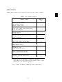
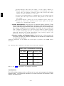
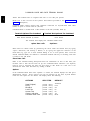
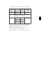
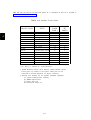
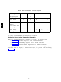
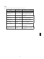
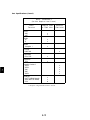
System Features
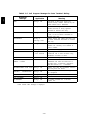
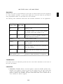
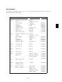
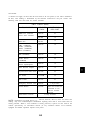
System features (Table 2-A) are those that affect the entire system’s operation.
TABLE 2-A. System Features
Feature Name
Automatic Route Selection
Call Accounting System
Dictation System Access
Direct Group Calling
Direct Group Calling Delay Announcement
Direct Inward Dialing
End-to-End Signaling
Extended Stations
External Alerts
Hold Release On Abandon
Intercept Treatment With Reorder Tone
Interdigit Timeouts
Music-On-Hold or Delayed Access
Night Service (Directed and TAAS)
Night Service Delay Announcements
Off-Premises Stations
Out-Of-Building Stations
Paging System Access
Pause
Personal Dial Codes
Pooled Facility-Dial Access
Power Failure Transfer
Remote Administration Interface
Station Message Detail Recording
Tie Trunks
Touch-Tone And Dial Pulse Service
Trunk Groups
Feature *
Type
c
o
o
c
o
o
s
o
o
s
s
s
I
I
o
c/o†
o
o
o
o
s
s
s
o
o
o
o
s
s
* Feature types are: S= Standard, C= Custom, O= Optional.
Custom features require administration, Optional features require
administration and additional equipment.
† C/O - Custom for Directed, Optional for TAAS Night Service.
2-3
I
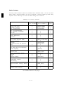
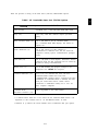
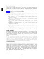
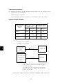
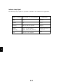
Station Features
2
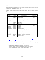
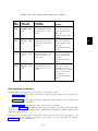
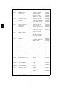
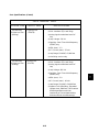
The many Station Features (Table 2-B) available allow individual needs to be met. As these
needs change, assigned features can also be changed. Station Features provide many
important services that help save time and make calling more convenient.
TABLE 2-B. Station Features
Feature
Name
Single-Line
Voice Terminal
Multiline
Voice Terminal ‡
Feature
Type *
x
[ACCT ENTRY]
[AUTO ICOM]
[COVER-GRP]
[COVER-IND]
x
x
x
x
x
x
[DSS or FLEX DSS]
x
[EXCLUSION]
[AUTO ANS]
x
x
x
[SIGNAL]
x
[PERS LINE]
[FACILITY]
x
x
[REP DIAL]
x
x
x
s/c †
c
c
c
s
s
s
c
s
s
c
s
c
o
s
s
s
c
s
c
c
s
s
c
s
o
S/C†
c
c
s
s
s
Account Code Entry
Automatic Intercom
Call Coverage-Group
Call Coverage-Individual
Call Following (Forwarding)
Call Park
Call Pickup
Calling Restrictions
Conference
Conference Drop
Direct Station Selection (DSS)
Distinctive Ringing
Exclusion
Hands-Free-Answer On Intercom
Hold
Line Selection
Line Status And I-Use Indications
Manual Signaling
Messaging Services
Personal Lines
Pooled Facility-Button Access
Program
Recall
Repertory Dialing
Speaker (Spokesman Service )
Speakerphone Adjunct
Speed Dialing
Station Hunting
Station-To-Station Message Waiting
Test
Transfer
Trunk-To-Trunk Transfer
x
x
x
x
x
x
x
x
x
x
x
x
x
x
x
x
x
x
[MSG WAIT]
x
x
x
(see footnotes bottom of next page)
2-4
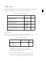
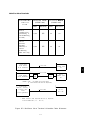
Attendant Features
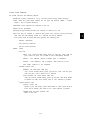
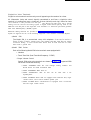
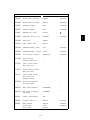
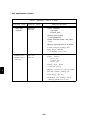
Attendant Features (Table 2-C) are available to the attendant using the Direct Trunk
Console and (optionally) a Direct Extension Selector (DXS) Console. In addition, all
multiline voice terminal station features are available to the attendant.
TABLE 2-C. Attendant Features
Feature Name
Console Button
Label ‡
Attendant Call Transfer
Attendant Camp-on
Attendant Cancel
Attendant Direct Extension Selection
Attendant Message Waiting
Attendant Position Busy
Attendant Release
Attendant Return Coverage on Busy.
Attendant Return Coverage on Don’t Answer
Attendant Splitting One-Way Automatic
Attendant System Alarm Indication
Night Service
Feature
Type *
[START]
s
s
s
o
s
c
s
s
s
s
s
c
[CANCEL]
[ATT MSG]
[POS BUSY1
[RELEASE]
[RTN-BUSY]
(RTN-DA)
[ALARM]
(NIGHT1
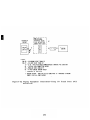
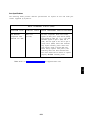
Data Features
Data Features (Table 2-D) support the system’s switched data services.
provide switched connections between analog and digital data endpoints.
Data services
TABLE 2-D. Data Features
Feature Name
Multiline Terminal
Button Label ‡
Command Mode
Data Terminal Dialing
Modem Pooling
One-Button-Transfer to Data
[DATA]
Feature
Type *
s
s
o
c
*
Feature types are S= Standard, C= Custom, O= Optional.
Custom features require administration, Optional features require
administration and additional equipment.
†
S/C - Standard for single-line/Custom for multiline voice terminals.
‡
Bracketed items are associated voice terminal feature button labels;
these labels are also used in feature descriptions where applicable.
2-5
2
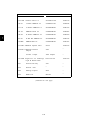
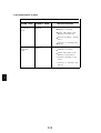
ACCOUNT CODE ENTRY
Description
2
Allows voice terminal users to associate an account code with incoming and outgoing calls.
This is accomplished by entering the account code at the voice terminal before hanging up.
The account code is appended to the SMDR call record and can be used later for accounting
or billing purposes.
To associate an account code with a call, the user, after completing a call but before hanging
up, must:
●
Single-Line Voice Terminal User:
-
●
Flash the switchhook, dial *O, and then dial the account code directly or dial a
System or Personal Speed Dial Number that contains the account code.
Multilane Voice Terminal User:
- Press Account Code Entry (ACCT ENTRY) button and then dial the account
code directly or dial a System or Personal Speed Dial Number that contains
the account code. A Repertory Dial (REP DIAL) button may also be used to
enter an account code.
●
When the correct number of account code digits have been entered, Confirmation
Tone followed by Dial Tone is returned to the user and the account code is appended
to the SMDR call record.
Account Code Entry is optional.
Considerations
Account Code Entry provides an easy method of allocating the costs of specific calls (and
associated staff time) to the correct project, department or user. The account code is
appended to the SMDR call record and sent to the SMDR output channel.
Account Codes can include up to 15 digits.
The validity of the entered account code is not checked by the system.
If the user is active on a call, invoking the featyure will dropthe call.
Incorrectly dialed codes (prior to last digit entry) may be corrected via a second switchhook
flash or pressing ACCT ENTRY and reentering the code. Partial account codes entered by
going on-hook before completing entry are recorded and cannot be corrected.
If, before all digits have been entered, (1) the user goes on-hook, (2) a button other than
ACCT ENTRY is pressed, or (3) 30 seconds have elapsed since the feature was invoked, the
SMDR call record will show the digits dialed up to that point.
If a call is on hold, this feature cannot reinvoked.
2-6
Interactions
●
●
●
●
Conference:
If more than one user attempts to enter an account code on a
Conference Call, the first to enter a code will prevail.
Repertory Dialing: An Account Code may be stored on a REP DIAL button. Press
REP DIAL at the point where ACCT ENTRY would normally be pressed.
Speed Dialing:
Number.
An Account code may be stored in System or Personal Speed Dial
Transfer: A user may transfer a call to another user, then, instead of hanging up,
enter an account code. Subsequent account code entries for the same call will be
ignored.
Administration
System:
●
Maximum number of Account Code digits (0-15)--Default = 15.
Voice Terminal: (Station Port)
●
Multiline terminals–Account Code Entry Button is required.
●
Single-line
terminals—none.
Hardware Requirements
Requires a RS-232C compatible 80-column ASCII (serial) printer or other output device.
2-7
ATTENDANT CALL TRANSFER
Description
Allows the attendant to transfer an incoming call using the Attendant Console START and
RELEASE buttons or the (optional) DXS console.
While the Attendant Console has a button labeled TRANSFER, this button invokes the
standard multiline voice terminal Transfer feature and should not be used by the attendant
to extend incoming calls. The Attendant Call Transfer feature described below should be
used for this purpose.
To extend an incoming call, the attendant, after answering the call can either:
1. Press START which places the incoming call on hold via the Attendant Splitting
One-Way Automatic feature. After receiving Dial Tone, the attendant then dials
the requested extension
or
2. Press the DXS Console button associated with the requested station. This operation
is equivalent to pressing START and dialing the extension.
If ringing tone is heard, the attendant either presses (1) RELEASE (Manual Release) or (2)
any facility button such as System Access, Automatic Intercom, or an outside line
(Attendant Automatic Release) to complete the transfer.
If busy tone is heard and Attendant Camp-On (see associated feature description) is not
desired, the attendant presses CANCEL and is reconnected to the calling party.
If Busy Tone is heard and Attendant Camp-On is desired, the attendant presses RELEASE
or any facility button. The called party hears a tone burst and the call is held at the called
voice terminal. When a busy single-line station goes on-hook, or a busy multiline station
System Access button becomes idle, the call automatically begins ringing at the station.
Only one Camped-On call is permitted per voice terminal.
Calls extended to an idle voice terminal that are not answered within a specified time
return to the Attendant Console on the Return-On-Don’t-Answer (RTN-DA) button. Calls
camped-on at a busy voice terminal that are not answered within a specified time return to
the Attendant Console on the Return-On-Busy (RTN-BUSY) button. If these buttons are
busy on another call, the extended call remains at the called terminal until that button
becomes idle.
Considerations
Attendant Call Transfer allows the attendant to utilize the additional attendant related
features such as Attendant Splitting One-Way (automatically places incoming call on hold),
Return On Don’t Answer, Return On Busy, Release, and Cancel.
2-8
Interactions
Refer to the following feature definitions for additional feature related information:
●
A t t e n d a n t Camp-On
●
Attendant
Direct Extension Selection
●
Attendant
Release
●
A t t e n d a n t Return Coverage On Busy
●
Attendant
Return Coverage On Don’t Answer
●
Attendant
Splitting One-Way Automatic.
Administration
System:
●
●
Number of seconds before a Camped-On call returns to the Attendant Console (1-120
seconds), or No Attendant Camp-On (0) - Default = 30 seconds
Number of rings before unanswered call returns to the Attendant Console
(1-31) - Default = 5.
Hardware Requirements
DXS Console (optional)
2-9
ATTENDANT CAMP-ON
Description
Allows the attendant to extend an outside call to a busy single-line voice terminal or a
multiline voice terminal active on both System Access buttons. When the attendant releases
from the call, a burst of tone is heard at the called terminal. The caller is placed on hold
and hears music-on-hold, if available. When a System Access button becomes idle or the
single-line terminal hangs up, the held call is connected automatically and ringing begins.
Only one call may be camped-on to a voice terminal. This feature is referred to as a
“Waiting Call” in the User Guides (555-500-700 series).
Note: Only outside calls can receive Camp-On service. If the attendant provides coverage
for a station whose incoming call has been redirected to the attendant, the call is considered
an inside call and can not be given camp-on service.
Considerations
A camped-on call can be answered by a busy single-line user without losing the current call
by momentarily pressing the switchhook (which places the current call on hold) and then
dialing *9. Multiline terminal users cannot do this. However, if they have a System AccessOriginate button they can place both calls on hold, go off-hook on that button and dial *9 to
pick up the camped-on call.
If the camped-on call is not answered within a specified time, the call will be returned to the
Attendant - Console Return-On-Busy (RTN-BUSY) button. If that button is busy, the call
remains camped-on until the button becomes idle.
Interactions
●
●
●
Call Coverage/Direct Group Calling: If the called party is a member of a hunt
(DGC or Call Coverage) group and all members of the group, or all receivers of the
Coverage group are busy, the call will not hunt or receive coverage. Once camped-on,
calls will no longer hunt or receive coverage even if the hunted-to station or group
member becomes idle.
Direct Group Calling: The attendant can camp-on one call per DGC group. Voice
terminals in the group do not receive a burst of tone when a call is camped on. If the
attendant attempts to camp-on a second call, it is immediately returned on the RTNBUSY button.
Direct Inward Dialing: DID calls may be covered by the attendant and then given
Camp-On treatment. They do not automatically receive Call Waiting.
Administration
System:
●
Number of seconds before a camped-on call returns to the Attendant Console (1-120
seconds) or No Attendant Camp-On allowed (0) - Default = 30 seconds.
Hardware Requirements
None
2-10
ATTENDANT CANCEL
Description
Allows the attendant to terminate an attempt to extend any incoming call if the called
station does not answer or if the station answers but declines to accept the call. Before
pressing RELEASE, the attendant presses CANCEL and is automatically reconnected to the
calling party.
Pressing CANCEL when the Start facility is not active will be ignored.
Considerations
Attendant Cancel allows the attendant to terminate a call transfer attempt and return to
the incoming held party via a one-button operation. This enhances the attendant’s ability to
handle calls quickly and efficiently.
Interactions
None
Administration
None Required
Hardware Requirements
None
2-11
ATTENDANT CONSOLE
The Attendant Direct Trunk Console (Attendant Console) is used to facilitate the completion
of incoming calls, place outgoing calls, and manage and monitor some of the system’s
operation. Special attendant related features simplify inward call transfer and the servicing
of unanswered calls. Each system may be equipped with up to two Attendant Consoles
(Primary and Secondary) which can operate simultaneously. The Attendant Console is a 34button deluxe console; all standard multiline voice terminal features are also available to the
attendant.
Each attendant may also have an associated Attendant Direct Extension Selector (DXS)
Console. The DXS Console operation is described in the “Attendant Direct Extension
Selection” feature description.
Unique feature buttons and associated status LEDs on the Attendant Console are:
●
●
●
●
●
●
●
●
●
Start [START] Initiates an inward call transfer by placing a caller on-hold and
provides internal dial tone to the attendant
Cancel [CANCEL] Terminates the “Start” operation and reconnects the attendant
to the calling party.
Release [RELEASE] Releases the attendant from an active call. When used on a
call that the attendant is in the process of extending, Release completes the transfer.
Return-On-Busy [RTN-BUSY} Calls extended to a busy station are returned to
the console if not answered within a specified interval.
Return-On-Don’t-Answer [RTN-DA} Extended calls not answered are returned
to the console if not answered within a specified interval.
Position Busy [POS BUSY]: In a dual attendant console system, Position Busy
removes an Attendant Console from service. Only one of two consoles can be in the
“Position Busy” mode at a time.
Night Service [NIGHT]: Used to activate/deactivate the Night Service feature.
Attendant Message Waiting [ATT MSG] Used by the attendant to turn On or
Off Message LEDs on voice terminals so equipped.
Alarm [ALARM] Status LED–Indicate that a system trouble has been detected.
Position Busy and Night Service are custom features; these buttons must be assigned to the
Attendant Console if the feature is required.
2-12
If the system has two Attendant Consoles, one console is considered to be the primary
console and the other the secondary console.
Dual Attendant Console Operation
The following calls will be routed to the primary console. If the primary attendant has
activated the Position Busy feature or is busy on both System Access buttons, these calls will
be routed to the secondary console. If that console is also busy on both System Access
buttons, busy tone is provided to the calling party. The call types are:
●
Dial “0” calls
●
DID calls to unassigned numbers (when administered to route to the attendant)
●
●
Calls to Floating PDCs (FPDCs) not logged in (when administered to route to the
attendant)
Calls on incoming facilities that terminate on that console.
System users and DID callers may reach a particular attendant by dialing that attendant’s
PDC.
A POS BUSY button can be assigned to each console; this permits selection of one of two
modes of operation: (1) simultaneous operation or (2) only one Attendant Console active.
However, only one console is allowed to be inactive at any given time. An associated POS
BUSY status LED is lighted when the console is inactive. Ringing is disabled on all trunk
terminations on the busy console’s rightmost two columns of buttons. Ringers disabled on a
busy console will be enabled on the active console for those trunks with dual appearances
(appearances on both consoles). All other features on all buttons, including those on the
associated Attendant Direct Extension Selector (DXS) Console will continue to function
normally even though the console is inactive.
The Attendant Position Busy feature description provides additional information.
Administration
System:
●
●
●
●
●
Assign Primary and Secondary Attendant Positions
Assign number of rings before unanswered calls return to the Attendant Position
(1-31) - Default = 5 rings
Send DID calls to unassigned numbers to the Attendant Position (Yes, No) - Default
= Yes
Send calls to Floating Personal Dial Codes that are not logged-in to the Attendant
Position (Yes, No) - Default = Yes
Assign number of seconds before an unanswered Camped-On Call returns to the
Attendant Console (1-120 seconds), or No Attendant Camp-On (0) - Default = 30
seconds.
2-13
Attendant Console: (Station Port)
●
Special Programmable Buttons:
— Night Service
Position Busy
— Attendant Message Waiting (assigned by default).
NOTE: The following buttons or LEDs are predefined on the Attendant Console and
are not administrable:
— Alarm (LED)
— Return-On-Don’t-Answer
— Return-On-Busy
— Start
— Cancel
— Release
●
Trunk terminations—The following is required for each trunk terminated on the
console (administered as Personal Line appearances):
— Trunk Number
— Make This The Principal Station (owner) of the trunk (Yes, No)
— Enable Ring (Yes, No).
2-14
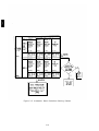
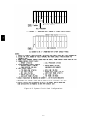
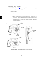
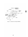
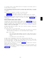
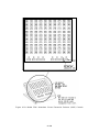
ATTENDANT DIRECT EXTENSION SELECTION
Description
Permits the attendant to extend calls to stations by pressing a single button instead of
pressing START and dialing the PDC or DDC. The primary and secondary Attendant
Consoles each may have an associated Direct Extension Selector (DXS) Console.
The DXS Console has an array of 100 DXS buttons plus seven Group Select buttons.
Pressing a Group Select button causes the DXS buttons to be associated with PDCs from an
associated hundreds group. Default assignments for the Group Select buttons are 200-299,
300-399, etc., up to 800-899. Group Select buttons can be assigned any hundreds group in the
dialing plan.
Pressing a DXS button when off-hook on an incoming call is equivalent to pressing START
and dialing a station. Such action will busy out the Start facility until the call is released.
When the attendant is already active on the START button, the system will ignore a DXS
button press.
The DXS LED associated with a particular station will flash when: (1) a station calls the
attendant, (2) a call extended to a station returns on the Return-On-Busy (RTN-BUSY) or
Return-On-Don’t-Answer (RTN-DA) buttons, (3) an extended call is directed to a Cover
button on the Attendant Console. The LED stops flashing when the call is answered. On
Return-On-Busy or Return-On-Don’t-Answer calls the LED status will return to the state
that reflects the stations current busy/idle status when the call is answered by the
attendant.
An outside call may be parked via the DXS Console by pressing one of the eight Call Park
buttons that may be programmed on the Console. On the Attendant Console, the facility
status LED of the parked call winks (to indicate that the call is held) and the status LED on
the DXS Console lights steadily.
A call parked via the DXS Console and not picked up within two minutes will return to the
RTN-DA button.
A call parked via the DXS Console may be picked up at any voice terminal by dialing the
Call Park retrieval code (*8) and the number of the DXS button used to park the call.
The rightmost button on the bottom of the console is a Test button. When it is pressed, all
DXS LEDs will light sequentially; a second press allows individual LEDs to be tested and a
third press ends the test.
Dual Attendant DXS Consoles
When there are two Attendant DXS Consoles in the system the Group Select button
assignments are identical. Whenever an administrative change is made to one console, the
other console is automatically changed.
2-15
Considerations
Buttons on the DXS Console point to either station PDCs or floating PDCs (FPDCs). Calls
extended by the DXS console are directed as described in the “Personal Dial Codes” feature
description.
When a station calls the attendant, the associated LED on the DXS Console will flash while
the call is ringing and will light steadily when the attendant answers the call. The LED will
light steadily whenever the terminal is off-hook. Station busy indication is not provided for
buttons pointing to floating PDCs (FPDCs).
If a call to a PDC is directed to a Cover button on the Attendant Console, the covered voice
terminal’s status LED on the DXS Console will flash and then light steadily when the call is
answered by the attendant. If the covered call was intended for a FPDC which was logged in
at a terminal with attendant coverage, the DXS Console status LED associated with the
FPDC (if assigned) will not light. In this case, just the Cover button status LED will light.
A call may arrive at an Attendant Console System Access button because the PDC or FPDC
is logged in at the Console or because the FPDC is not logged in. For these calls, the status
LED on the DXS Console will not light.
If the attendant extends a call to a station and that call returns to the attendant, then the
station’s status LED on the DXS Console will flash and then light steadily when the call is
answered by the attendant. This is true regardless of the login status of the PDC. If the
attendant extends a call to a FPDC and that call returns to the attendant then the FPDC
status LED on the DXS Console will not light.
Interactions
●
●
●
●
Attendant Position Busy: The DXS Console functions normally when the
associated Attendant Direct Trunk Console is in the inactive mode.
Attendant Return Coverage On Busy/Or Don’t Answer: If a call to a FPDC is
returned to the attendant on a RTN-BUSY or RTN-DA button, the FPDCs status
LED on the DXS Console will flash during ringing and light steadily when answered.
Call Coverage: If the attendant receives a coverage call for a FPDC, the associated
status LED on the DXS Console will not light.
.
Direct Extension Selection: When all stations is a DGC group are busy, the
status LED on the DXS Console lights.
Administration
Special Feature Ports:
●
●
Assign Group Select button hundreds groups and Call Park codes.
Requires a port assignment on a ZTN-79 ATL Line Circuit Pack (CP) for each DXS
Console.
Hardware Requirements
Requires an Attendant DXS Console, and a port interface on a ZTN-79 ATL Line CP.
2-16
ATTENDANT MESSAGE WAITING
Description
Allows the attendant to control the status of Message LEDs on stations so equipped.
Considerations
This feature allows the attendant to notify stations that a message is available for them.
The attendant can activate the station’s Message LED while either (1) ringing, (2) receiving
Busy Tone, or (3) talking to a station. The status of the called party’s Message LED is
reflected by the Attendant Message Waiting (ATT MSG) status LED in any of these cases.
To activate (light) a user’s Message LED in any of these cases, the attendant presses the
ATT MSG button. If the voice terminal is not equipped with a Message LED, the attendant’s
LED will remain dark.
If the attendant presses ATT MSG a second (or third) time before hanging up, the user’s
Message LED will turn Off’(and back On), etc.
The red I-Use LED associated with the ATT MSG button does not light.
The attendant can turn On or turn Off a user’s Message LED without disturbing the user by
going off-hook on a System Access button, pressing ATT MSG to obtain the required state,
and then dialing the station. Confirmation Tone is returned.
This feature is not the same as the Station-To-Station Message Waiting or the Call Coverage
Cover Message Waiting features. Refer to the ’’Messaging Services” feature description for a
summary of all system Messaging Services.
Interactions
●
●
Conference: Pressing ATT MSG while on a conference call will be ignored.
Hands-Free-Answer On Intercom: If the attendant lights the Message LED on a
HFAI/BIS terminal with AUTO ANS button active, the auto-answer function will
turn off, allowing subsequent calls to receive coverage as assigned.
Administration
Attendant Position: (Station Port)
●
Assign ATT MSG button
(defaulted).
Hardware Requirements
Stations must have a Message indicator LED (not assignable).
2-17
ATTENDANT POSITION BUSY
Description
Allows an Attendant Console to be placed in an inactive mode.
There must be two Attendant Consoles in the system before this feature can be activated. A
Position Busy (POS BUSY) button may be assigned on each of the consoles. Pressing POS
BUSY at one of two active consoles causes the POS BUSY status LED to light and the
console to be placed in the inactive mode. Pressing POS BUSY a second time causes the
LED to go dark and the console to be reactivated. Pressing POS BUSY when only o n e
Attendant Console is active is ignored (i.e., only one console is allowed to be inactive at a
time. )
When a console is in the inactive mode, ringing is disabled on facility appearances on the
two rightmost button columns o n l y . The (green) status LEDs will continue to operate
normally. Calls to floating PDCs not logged in, DID calls, and dial “0” calls will be
transferred to the active console. Internal calls to the inactive console’s PDC will still be
directed to that console.
Incoming calls on lines that normally ring at only the inactive console will now ring at the
active console if they have an appearance there.
All buttons on the inactive console will continue to function normally, including the DXS
Console buttons. Calls may be originated by the inactive console. Call appearances in the
leftmost two columns of buttons on the inactive console are not affected by the Position Busy
feature.
The attendant can press a Direct Station Selection (DSS), Automatic Intercom (AUTO
ICOM), or a Pooled Facility-Button Access (FACILITY) button and then receive busy-to-idle
reminder when the facility becomes idle.
Considerations
Position Busy allows one of two attendant positions to be deactivated when not required.
This is useful in situations where calling traffic requires only one console operator.
All dial ``O'' calls, calls to floating PDC's not logged in, calls to unassigned DID numbers, and
calls to facilities in the rightmost two columns of buttons of the console that appear at both
consoles will be directed to the active console.
Note that if a trunk appears on only one console, incoming calls on those trunks will not
receive service when the console is inactive. For this reason, it is strongly recommended
that each attendant be assigned a Call Coverage-Individual (COVER-IND) button for the
other console so that these calls can be covered. Also, be sure to make the Attendant
Console the principal station (owner) on all trunks that are to receive coverage by the other
attendant.
Interactions
●
●
Attendant Call Transfer: Unanswered calls extended by an inactive console will
return to the active console on the Return-On-Don’t-Answer (RTN-DA) button.
Attendant Camp-On: Calls Camped-On by an inactive console will return to the
active console when Camp-On timeout occurs.
2-18
●
●
●
●
●
●
●
●
●
●
●
Attendant Message Waiting: An inactive attendant is permitted to control voice
terminal Message LEDs.
Automatic Intercom: The inactive attendant is permitted to place Automatic
Intercom calls. Automatic Intercom calls to the inactive attendant will not ring at
the console or be transferred to the active attendant when the AUTO ICOM button is
located in one of the two rightmost button columns
Call Coverage: If the active attendant is a coverage receiver for the inactive
attendant, coverage is invoked and calls will appear at the active attendant’s Cover
button. If the inactive attendant is a coverage receiver for the active attendant,
coverage, when activated, is invoked at all coverage stations including the inactive
attendant. However, if the Cover button is located in one of the two rightmost
button columns, coverage calls will not ring at these buttons.
Call Park: A call parked by an inactive attendant will return to the inactive
attendant on the button the call was parked on if the call times out.
Direct Group Calling: If the inactive attendant is a member of a DGC Group, calls
directed to the group will be routed to the inactive attendant. The attendant must
dial *4 (activate DGC Group “Make Busy”) to busy out from the group. Dialing *6
deactivates the “Make Busy” function.
Direct Inward Dialing: All DID calls to unassigned DID numbers will be
transferred to the active attendant.
Night Service: An inactive attendant that is a Directed Night Service receiver will
receive Night Service calls.
Personal Dial Codes: All calls to floating PDCs not logged in will be transferred
to the active attendant.
Personal Lines (Trunk Appearances) : All calls to trunks having an appearance
in either of the two leftmost button columns will ring normally at the inactive
console. All calls to trunks having appearances in either of the two rightmost button
columns will not ring. If these trunks also have an appearance at the active console,
they will ring there even if they don’t normally.
Program: The Program feature remains active at the inactive console.
Programmable Buttons: All DSS, REP DIAL, and Speed Dial buttons remain
active on the inactive console.
Administration
Voice Terminal: (Station Port)
●
Assign Position Busy button (button function #18)
●
Assign COVER-IND buttons between consoles.
Hardware Requirements
None
2-19
ATTENDANT RELEASE
Description
Releases the attendant from an extended call. There are two forms of Attendant Release; (1)
Manual Release, (2) Automatic Release.
Manual Release:
Pressing RELEASE releases the attendant from an extended call and completes the
associated call transfer. The status LED of the original calling facility will change from
hold to busy for direct trunk terminations and from hold to idle for other call facilities (e.g.,
Return On Busy, Return On Don’t Answer, Cover, Automatic Intercom, DSS, and System
Access).
Calls cannot be released to Reorder or Dial Tone.
Pressing CANCEL reconnects the attendant to the incoming call. If the attendant goes onhook without first releasing a call, the call transfer operation will be terminated (the calling
party remains on hold). In this case, the attendant can go off-hook and press the held call
appearance button to reconnect to the incoming call.
Automatic Release:
This feature simplifies the attendant procedures by eliminating the need for the attendant to
press RELEASE when releasing from one call to answer another. Selection of any new line
facility while active on the Start button will automatically release the first call. At release,
the status LED of the first calling facility will change from hold to busy for direct trunk
terminations and from hold to idle for other call facilities (e.g., Return On Busy, Return On
Don’t Answer, Cover, Automatic Intercom, DSS, and System Access).
Considerations
Attendant Manual Release improves attendant efficiency in handling calls by allowing the
attendant to release an extended call without having to wait for the called station to answer.
Attendant Automatic Release enhances the attendant’s ability to handle many calls by
eliminating the Release operation when answering a second call.
The Release function is inhibited whenever the Start facility is connected to Reorder or Dial
Tone. Pressing CANCEL will reconnect the attendant to the calling party.
Interactions
●
Attendant Camp-On: Calls released when Busy Tone is heard will be camped on.
Administration
None Required
Hardware Required
None
2-20
ATTENDANT RETURN COVERAGE ON BUSY
Description
Allows a camped-on call at a busy station or DGC Group to be returned to the attendant for
service after a specified time period.
A camped-on call not answered within 1 to 120 seconds (administrable) after the attendant
releases the call, will return on the Return-On-Busy (RTN-BUSY) button.
To answer a returned call, the attendant presses RTN-BUSY (if not selected by Ringing Line
Preference. ) A returned call may be reextended via the “Start” button or DXS Console. In
either case, the Return-On-Busy button is idled as soon as the attendant releases.
When the RTN-BUSY button is busy, the calling party w-ill remain on-hold. The system will
continue to attempt to ring the called station until the RTN-BUSY button is idle. When
Attendant Camp-On is not provided (Camp-On return time set to zero seconds], calls
released by the attendant to busy tone are returned immediately to the RTN-BUSY button.
Considerations
Attendant Return Coverage On Busy allows the attendant to service calls not answered
within specified time intervals. This provides the calling party better service and results in
fewer lost calls.
Interactions
●
●
●
Attendant Camp-On: Calls released when Busy Tone is heard will be camped on.
Attendant Console: As long as an Attendant Console remains active, the call will
return to the attendant who transferred it.
Attendant Direct Extension Selection: If a call to a Floating PDC (FPDC) is
returned to the attendant on the RTN-BUSY button, the FPDCs status LED on the
DXS Console will flash during ringing and light steadily when the call is answered.
Administration
System:
●
Assign number of seconds before unanswered camped-on calls return to
Attendant Position (1-120 seconds, or O for No Camp-On) - Default = 30 seconds.
Hardware Requirements
None
2-21
the
ATTENDANT RETURN COVERAGE ON DON’T ANSWER
Description
Allows unanswered calls extended by the attendant to be returned to the attendant for
additional service.
Calls that are not answered after a specified number of rings will transfer ringing to the
Return-On-Don’t-Answer (RTN-DA) button on the Attendant Console. If the called voice
terminal has call coverage, the timing for return begins only after the coverage station
begins ringing.
When the RTN-DA button is busy, calls will continue to ring at the called station until the
button is idle.
To answer a returned call, the attendant presses RTN-DA (if not selected by Ringing Line
Preference.) The call may be reextended via the START button or DXS Console. In either
case the button is RTN-DA button is idled as soon as the attendant releases.
Considerations
Attendant Return Coverage On Don’t Answer allows the attendant to service calls not
answered within specified time intervals. This provides the calling party better service and
results in fewer lost calls.
Interactions
Attendant Console: As long as an Attendant Console remains active, the call will
return to the attendant who transferred it.
●
Call Coverage: Whenever the attendant is a call coverage receiver for a particular
call coverage group and a call is placed from the attendant position via the Start
button or the DXS Console to a voice terminal in that group, the Call CoverageGroup (COVER-GRP) button on the Attendant Console will not track the call
(COVER-GRP button status LED will not flash). If the call remains unanswered, it
will return to the Attendant Console on the RTN-DA button rather than the
COVER-GRP button.
●
Administration
System:
●
Assign number of rings before call return to the Attendant Position
(1-31) - Default = 5 Rings.
Hardware Requirements
None
2-22
ATTENDANT SPLITTING ONE-WAY AUTOMATIC
Description
Allows the attendant to converse privately with a called party while the calling party is split
away on hold.
When the attendant presses START (or a DXS button) to extend an incoming call to a called
party, the calling party is automatically split away from the connection and placed on hold.
This allows the attendant to talk privately with the called party before extending the call.
The attendant can then press RELEASE to complete the transfer or CANCEL to drop the
called station and return to the incoming call.
Considerations
Attendant Splitting One-Way Automatic allows the attendant to (1) announce a call, (2)
determine privately whether the called party is available to receive the call, and (3) obtain
information if necessary to redirect the call or take a message.
Interactions
. Music-On-Hold: Music-on-hold is not provided to the calling party while they are
on hold.
Administration
None Required
Hardware Requirements
None
2-23
ATTENDANT SYSTEM ALARM INDICATION
Description
Provides an Alarm on the Attendant Console to alert the attendant to problems detected by
the system software.
The ALARM LED on the Attendant Console will light whenever a detected fault persists
longer than four minutes, or if more than five transient faults per hour are detected. The
alarm indication should be reported immediately to your AT&T Systems Technician.
The alarm type that causes an alarm indication is referred to as a Permanent System
Alarm. These alarms are faults that may cause degradation of service and require
immediate attention. These alarms are recorded in the Permanent System Alarm Table in
the maintenance error log.
Considerations
The ALARM LED on the Attendant Console provides a warning as soon as the fault is
detected. This permits a quick response to system detected faults.
Interactions
None
Administration
None Required
Hardware Requirements
None
2-24
AUTOMATIC INTERCOM
Description
Allows multiline voice terminal users to place and answer calls to and from each other by
use of a dedicated line appearance.
Automatic Intercom provides a private path between two designated multiline voice
terminals. To place an Automatic Intercom call, the calling party presses the Automatic
Intercom (AUTO ICOM) button and goes off-hook. The calling party hears ringback tone
and the called party receives standard ringing. The status LED associated with the button
is steadily lighted at the calling voice terminal and flashing at the called voice terminal. To
answer an Automatic Intercom call, the called party presses AUTO ICOM (not necessary
with Ringing Line Preference) and goes off-hook.
The AUTO ICOM status LED lights steadily whenever the other party is off-hook. This
provides each party with a station busy indication for the other. To activate the busy-to-idle
reminder, the user can press AUTO ICOM (remaining on-hook). A short burst of tone is
provided when the other user goes on-hook.
Pressing AUTO ICOM to invoke the busy-to-idle reminder overrides Prime Line Preference.
Once activated, the feature can only be canceled by preelection of another button or
answering an incoming call.
Considerations
With Automatic Intercom, users who frequently call each other can do so by pressing one
button instead of dialing a PDC. In addition, the station busy indication and busy-to-idle
reminder provide additional utility to users.
This feature is similar to Direct Station Selection (DSS), except that the buttons must
always be assigned in pairs (i.e., between two sets.) Hence, an AUTO ICOM button cannot
point to a single-line set. Also, Automatic Intercom calls arrive at the AUTO ICOM button,
thereby providing calling party ID; DSS calls arrive on System Access buttons.
Interactions
●
●
Attendant Position Busy: The inactive attendant is permitted to place Automatic
Intercom calls. Automatic Intercom calls to the inactive attendant where the AUTO
ICOM button is located in one of the two rightmost button columns will not ring at
the console, nor can they be covered by the active attendant.
Call Coverage: Automatic Intercom calls are considered private and do not receive
call coverage.
●
●
●
Call Pickup: When an Automatic Intercom call is picked up via Call Pickup, the
AUTO ICOM status LED on the called voice terminal lights steadily. The called
party can press AUTO ICOM to enter the call at any time.
Direct Group Calling: Automatic Intercom calls cannot be directed to DGC groups.
Exclusion: Any attempt to engage Exclusion while active on an Automatic Intercom
call will drop the other party.
2-25
●
Line Selection (Prime Line Preference): When the Automatic Intercom line is
assigned Prime Line status, the AUTO ICOM button must be pressed to activate the
busy-to-idle reminder even though the I-use LED is already lighted steadily.
Administration
Voice Terminal: (Station Port)
●
Assign AUTO ICOM buttons to voice terminals. Voice terminals may have several
AUTO ICOM buttons assigned for direct access to multiple stations.
Hardware Requirements
None
2-26
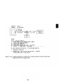
AUTOMATIC ROUTE SELECTION (ARS)
Description
Provides for the routing of calls over the telecommunications network based on preferred
routes (normally the least expensive route available at the time the call is placed. )
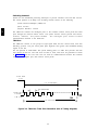
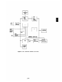
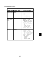
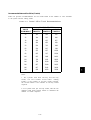
Call routing can be specified by as many as eight routing patterns. Each pattern contains a
sequential list of routes (i.e., trunk groups) the system can use to complete a call. Number
translations (deletion and addition of dialed digits) necessary to route the call is determined
on a trunk group basis. Overflow to the local CO when all trunks in a pattern are busy or
the route FRL is too high is optional. If all trunks in a pattern are busy (including CO
trunks if overflow is allowed), the call queues on the first route in the pattern.
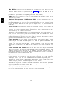
All calls placed using the ARS access code (default = 9) are routed via the feature. The
dialed numbers that follow the ARS access code are generally seven or ten digit DDD
numbers preceded by a “l” if required by the serving Central Office. Numbers preceded by a
“0” are routed over the local CO pooled facility.
Typically, a dialed 7-digit number consists of a CO code and exchange number in the form
NNX-YYYY where N = 2-9, X = 0-9, and Y = 0-9. A 10-digit number consists of an area
code, CO code, and exchange number in the form NPA-NNX-YYYY where N = 2-9, P = 0-1,
A = 1-9, X = 0-9, and Y = 0-9.
An ARS pattern can consist of two subpatterns (time of day determines which subpattern is
selected), each consisting of up to three routes, associated Facility Restriction Level (FRL)
codes (described below), and CO overflow flags. A route is identified by specifying a Facility
Access Code for the pooled facility (trunk group).
A trunk group can be used in more than one ARS pattern and more than once within a
pattern.
Each route in a pattern has an associated FRL (0-3). This FRL may differ each time the
facility is specified as a route. A facility with a FRL of “0” is least restricted to callers; a
FRL of “3” is the most restricted. Similarly, each station in the system is assigned an FRL
(0-3),. A terminal assigned an FRL of “0” has the least ARS privileges (i.e., routes with
FRLs of 1-3 are restricted); a FRL of “3” provides the most privileges. A station’s FRL
must be equal to or greater than the routes FRL to use the route.
The ARS feature, when accessed, selects a pattern as follows:
●
Emergency Number Calls (routed via the local CO facility)
●
International Calls (routed via the international pattern)
●
●
Calls made to specified COS or seven digit telephone numbers within the Home
Number Plan Area (HNPA). These calls are routed as specified in the HNPA
Exception Lists, or else via the NPA Routing Table or (by default if not otherwise
specified) the local CO facility.
Calls made to NPAs outside the HNPA, sometimes referred to as Foreign NPAs
(FNPAs). The route selected depends on the type of call, as follows:
— FNPA special number calls (includes all “800”, “900”, and Telex 510, 610, 710,
and 810 numbers). These calls are routed via the local CO facility.
— FNPA calls made to numbers specified in the FNPA Exception List.
— All other FNPA calls.
2-27
ARS Flow Chart
Figure 2-1 provides a simplified ARS flow chart. Bracketed numbers (e.g., [401], [601] )
provide a link between ARS administrable action numbers and the associated item on the
flow chart. Certain readers may find this reference useful when reading the following
description in association with the System Administration Manual (555-500-500).
Administrable System, Station, Toll Allowed, and Trunk action numbers are also noted
where applicable.
The ARS feature is accessed when a user dials the ARS access code. As shown on Figure 21, the number dialed is first checked against the Emergency Numbers List. This list consists
of special service codes (911) and up to three customer defined seven digit numbers. If the
number dialed matches one of the numbers on the list, the call is immediately routed via the
local CO facility. All user call restrictions are disregarded.
If the number dialed is not on this list, a check is made to determine if the voice terminal is
allowed to originate outside calls. If the terminal is outward restricted, the caller receives
Reorder Tone, otherwise, the dialed number is checked against any toll restrictions that
apply.
Terminals may be assigned a Toll Restriction Class (l-4), or be unrestricted (Class O).
Terminals assigned Toll Restriction Class 1 have the most privileges, those assigned Class 4
have the least privileges. There are four associated Toll Call Allowed Lists (l-4) in the
system. Up to 64 3-digit CO codes and 6-digit NPA plus CO codes may be assigned to the
four lists (total).
Numbers dialed from voice terminals assigned Toll Restriction Class 1 are checked against
all four Toll Call Allowed (TCA) Lists; numbers dialed from Class 2 terminals are checked
against TCA Lists 2-4; numbers dialed from Class 3 terminals are checked against TCA
Lists 3-4; and numbers dialed from Class 4 terminals are checked against List 4 only. If the
number dialed does not appear on a list (all operator and international calls are in this
category), the user receives Reorder Tone. Calls originated at unrestricted (Class O)
terminals are not screened. Calls are checked to determine if they are international calls or
operator calls. Dialed numbers “01” or “011” signify international calls, “O” plus a number
other than “l” signify operator calls. If the call is an international call, the international
routing pattern is selected and the call routed accordingly. Operator calls are routed via the
local CO facility.
.
Calls within the HNPA are checked against the HNPA Exception Lists. There may be up to
four of these lists, each with an associated ARS Routing Pattern. Up to 64 3-digit office
codes may be divided among the four lists (eight of the entries may be 7-digit numbers. ) If a
match is found, the call is routed via the associated ARS Routing Pattern. If no match is
found the dialed number is routed via the HNPA pattern (specified in the NPA Routing
Table), or if none is specified, via the local CO facility.
The NPA Routing Table is simply a listing of North American Plan NPAs, each having an
associated ARS Routing Pattern (all North American NPA’s are assigned routing pattern 1
by default.) A dialed NPA that is listed in the table is routed using the associated Pattern.
Calls to NPA’s not listed are routed via the local CO facility.
For calls outside the HNPA (FNPA calls), a check is made against a non-administrable
Special Numbers List. The numbers in the list include all “800” and “900” numbers and
Telex codes 510, 610, 710, and 810. If a match is found, the call is routed via the local CO
facility.
2-28
For FNPA calls not on the Special Numbers List, the dialed numbers are checked against the
FNPA Exception List. Up to 32 entries maybe assigned to the list. Each entry must consist
of a 3-digit NPA code, 3-digit CO code, and two additional digits (8-digits). The last two
digits may be “. .“, which match any digit. Each entry has an associated ARS Routing
Pattern. If a match is found, the call is routed using this pattern, If no match is found, the
call is then checked against the NPA Routing Table. A dialed NPA that is listed in the table
is routed using the associated Pattern. Numbers that don’t match are routed via the local
CO facility.
ARS Routing Pattern Table
Figure 2-2 provides a block diagram of an ARS Routing Pattern. Up to eight of these
patterns may be administered in the system. Each pattern consists of two subpatterns that
may be chosen based on the time of day. Each pattern consists of two subpatterns (A and B)
each of which can contain up to three allowed routes. If all routes in a subpattern are busy,
a CO overflow flag when set allows the call to be routed via the local CO facility, otherwise,
the call will queue on the first route in the subpattern.
Administrable Start and Stop times (Hour and Minute) for Routing Subpattern A specify
when Subpattern A should be used to route calls. Subpattern B is used to route calls at all
other times.
Each route is specified by its trunk group facility access code and an associated FRL.
An FRL is typically lower for the first route in a subpattern and increases with each
additional route in the pattern. A terminal’s FRL must be equal to or greater than the route
FRL for the route to be selected. The system first checks the Route #1 for an available
trunk on which to route the call. If the route is busy, Route #2 is checked, then Route #3, if
required. If all routes in the subpattern are busy and the CO overflow flag is set, the voice
terminal FRL is checked against an associated Overflow FRL before routing the call. If the
voice terminal is allowed access to the local CO trunk pool, the system, on overflow, will
attempt to place the call regardless of the associated FRLs.
If all routes in a subpattern are busy and the CO Overflow flag is not set, or all CO trunks
are busy, the call returns to the first route in the subpattern and is queued (if the station
FRL permits access to the first route). The caller is placed in an off-hook queue indicated by
five short bursts of tone (Preferred Routing Tone). The order of service in the queue is First
In First Out (FIFO). An ARS user placed in an off-hook queued state always has precedence
over users with a Pooled Facility access buttons. There are 16 slots available in the ARS
queue. A route #1 must be specified in the subpattern for a call to queue. If it is not, the
caller receives Reorder Tone instead of being queued.
Once a route has been selected, the entries in a Digit Translations Table associated with the
selected route’s trunk group is checked. Based on an associated NPA and the NPA dialed, the
system can remove up to 10 digits and then add up to 5-digits as specified to route the call.
The following tones are associated with ARS:
●
●
●
●
Confirmation–Indicates that a queued call is being serviced (trunk available to route
call )
Busy–Indicates that the called number is busy
Reorder—Indicates that all trunks are busy, the ARS queue is full, or that ARS
calling is denied.
Preferred Route Tone—Five very short tones that indicate that your call has been
queued for the preferred route.
2-29
Considerations
With ARS, users do not have to worry about accessing a particular pooled facility to make a
long distance call. The user simply dials the ARS access code and the desired number. The
system then routes the call via the facility best suited for that call.
The following provides a summary of the ARS call routing controls provided by the feature:
Emergency Numbers List: 911, and up to three customer defined 7-digit numbers
●
●
Toll Call Allowed Lists: 1-4 lists, 64 entries maximum between all lists. Entries
may be 3-digit NPA codes or 6-digit NPA plus CO codes. (Administrable for other
than ARS)
Station Toll Restriction Class: 1-4 Classes (Administrable for other than ARS)
●
HNPA Exception List: 1-4 Lists, each with an associated ARS Routing Pattern. 64
3-digit CO codes entries maximum between all lists (eight of the entries may be 7digit numbers.)
●
NPA Routing Table: Entries may include every North American NPA, each with
an associated ARS Routing Pattern. All NPAs are assigned Routing Pattern #1 by
default.
●
●
●
●
FNPA Special Numbers List: Routes all “800”, “900”, and Telex 510, 610, 710, and
810 numbers via the local CO trunk group (not administerable)
FNPA Exception List: One List with up to 32 eight-digit numbers. Each entry has
an associated ARS Routing Pattern.
Digit Translations Tables: One per trunk group (pooled facility) - (16 tables
maximum).
A system can have up to eight ARS Routing Patterns assigned. Each pattern can contain up
to six routes (three per subpattern).
Interactions
●
and Toll Restriction, when
Calling
Restrictions:
Outward Restriction
administered, prevent calls from routing via ARS. Pooled facility access restrictions
do not apply. In fact, the recommended arrangement to insure that users make
maximum use of ARS is to block dial access to most trunk groups so that users must
dial the ARS access code to place calls.
Pooled Facility-Button Access: Multiline voice terminal users who have pressed
FACILITY to activate the busy-to-idle reminder must wait until all queued ARS
users have been serviced.
●
Administration
System
●
Specify your area code (HNPA)
●
ARS Access Code (l-9999) - Default = 9
ARS
●
International ARS Routing Pattern Number (l-8) - No default
2-30
●
Three Emergency Numbers Lists (7-digit numbers) -No default
●
NPA Routing Table (NPA code and associated pattern number l-8)-Default = 1
●
HNPA Exception List:
— List Number (1-4)
Pattern Number (l-8)
— Exception Numbers (NNX or NNX-YYYY). Last 3-digits maybe “. . .“
●
FNPA Exception Telephone List
Pattern Number (l-8)
— Telephone Number (8-digits in the form NPA-NNX-YY). Last 2-digits maybe
'' ..''
●
Digit Translations Table
– Facility Access Codes (trunk groups) (l-9999)
– Associated NPA (NPA)
— Number of digits to remove for calls within associated NPA (0-10 digits)
– Digit pattern to add for calls within associated NPA (0-5 digits) - Default = 0
– Number of digits to remove for calls not in associated NPA (0-10, None) Default = 0
– Digit pattern to add for calls not in associated NPA (0-5 digits) - Default = 0
●
ARS Routing Pattern:
— Pattern Number (l-8)
– Subpattern A Start and End Time (Hour: Minute)
– Subpattern A and B–Route 1, 2, and 3 Facility Access Codes (l-9999)
— Subpattern A and B–Route 1, 2, and 3 FRLs (0-3)
– Subpattern A and B Overflows to CO facility (Yes, No)
– Subpattern A and B Overflow FRL (0-3).
Voice Terminal (Station Port)
●
ARS FRL Level (0-3).
Hardware Requirements
None
2-31
Figure 2-1. Automatic Route Selection Flow Chart (Sheet 1 of 2)
2-32
Figure 2-1. Automatic Route Selection Flow Chart (Sheet 2 of 2)
2-33
Figure 2-2. Automatic Route Selection Routing Pattern
2-34
CALL ACCOUNTING SYSTEM (CAS)
Description
Call Accounting Systems help customers control telephone use and manage associated costs.
The following AT&T Call Accounting Systems are available for use with System 25:
●
Models 200, 300, 500, and 2000–AT&T PC 6300 Software Based System
The System 25 Station Message Detail Recording (SMDR) interface provides several
customer options for obtaining telephone use and cost information:
●
Direct output to a printer (Refer to the SMDR feature description for additional
information.)
Direct output to a AT&T PC 6300 Personal Computer equipped with a CAS software
package (i.e., Model 200, 300, 500, and 2000) that calculates the cost of calls and
provides basic and sophisticated call reports.
CAS Models 200/300/500/2000
●
After a telephone call is completed, System 25 sends a call record to the AT&T PC 6300 via
the SMDR interface channel. The PC must be equipped with CAS software.
Call records are collected by the PC and held in a buffer until they are processed. When a
call record is processed, a cost is calculated and assigned to it. That cost, along with other
call record information, is then stored on a hard disk for subsequent retrieval.
Two modes of operation are available for PC 6300 operation:
●
●
Dedicated Mode: The PC is dedicated to one and only one task–processing call
records.
Multi-Function Mode: Allows the user to print reports, edit files, and run other
PC-based programs while the CAS continues to collect and buffer call records in the
background. The user must enter the Dedicated Mode to process calls and generate
reports.
The CAS performs three main functions; (1) call record processing, (2) report generation, and
(3) CAS system management. In addition, a limited directory lookup and message center is
provided. The following is a brief description of each function:
1. Process Calls: Involves screening call records, calculating the cost of valid calls,
and storing the call records.
2. Generate Reports: Allows the user to print the stored call record information
organized in one of several different ways. Users can select a report or setup their
own special combination of reports from the following:
●
●
Summary Reports— A collection of reports that condense and summarize
call record information by total number of calls, duration, and cost. The
reports can be organized by department, call type, cost center, trunk,
extension, cost, duration, time of day, date, and account code.
Organization Detail Report–A detailed report of each call record in the
system, sorted by department, cost center, and extension.
2-35
Selection Report—This report
detailed information based on
of day, date, cost, duration,
number, call type, department,
can contain at a user’s option, summary or
any combination of the following items: time
extension, access code, account code, dialed
or cost center.
Account Code Detailed Report– A detailed report on call records sorted by
account code. This report can be used for billing clients for calls made in
their behalf.
Preselected Reports— Allows up to five predefine reports which can
include any of the above mentioned reports. These reports can run upon
request or at a specified time and date.
3. System Management: A l lOWS the user to perform several functions. These
include editing the table of departments, cost centers, and extensions; setting up
account codes; defining preselected reports; and keeping call rate information up to
date. System configuration may be changed. This allows the user to inform the
CAS of changes in System 25 (e.g., dial access codes, trunks) or changes in charge
rates. System housekeeping may also be performed. This includes establishing
passwords, deleting call records, determining call processing options, and
performing various disk maintenance operations.
4. Directory Lookup and Message Center: Allows the user to look up anyone by
last name, first name, or extension. Messages can be recorded for individuals and
can be printed or displayed.
Additional information on the SMDR call record output is provided in the SMDR feature
description.
The following table summarizes CAS station and account code capacities.
AT&T CALL ACCOUNTING SYSTEMS
CAS Model
Stations
Account Codes
200
100
5000
300
150
5000
500
500
5000
2000
2000
15000
Refer to the CAS documentation for additional information.
Considerations
The CAS provides customers with an efficient tool to control and manage their telephone
usage and costs. The information available can be used to facilitate cost allocation, traffic
analysis, and abuse control.
2-36
Interactions
None
Administration
System:
●
Send SMDR Records To SMDR Port (Yes, No) - Default = Yes
●
Bill Call S Seconds After Last Digit Dialed (10-255) - Default = 40.
Hardware Requirements
Requires an AT&T PC 6300 equipped with CAS Model 200, 300, 500, or 2000 applications
software.
2-37
CALL COVERAGE—GROUP
Description
Allows calls to covered stations to be redirected to a group of covering stations.
A total of 32 CaIl Coverage Groups may be assigned. Each group maybe covered by up to
eight call coverage receivers (buttons). There is no limit on the number of covered users
(senders) that each Call Coverage Group can include, but a covered user can be assigned to
only one Call Coverage Group. Each call coverage receiver must have a multiline set
equipped with a Cover (COVER-GRP) button. A covering set may be assigned more than one
COVER-GRP button for the same or different groups.
Senders maybe either single-line or multilane voice terminals.
When a call arrives at a voice terminal that has group coverage, the COVER-GRP button
status LED at the covering voice terminals will flash. Covering voice terminals will begin to
ring after a specified number of rings at idle covered voice terminals. If there is no idle
COVER-GRP button, the call will not receive coverage treatment and the called station will
continue to ring.
Ringing may be turned off at covering stations at each covering button as desired (not
recommended). If this option is selected, a flashing status LED will be the only indication
received at the covering station. In addition, Call Coverage ringing may be turned off on
internal calls (if desired) on a system-wide basis.
The covering user can use the Line Selection (Preelection) feature to answer covered calls
even before any audible alerting has begun at the covering user’s terminal. This is useful if
the user knows that the covered party is unavailable.
A covered voice terminal may elect to have calls covered while it is busy on another call.
Calls directed to an idle button on a covered multiline voice terminal will start ringing at the
covering terminal after a single burst of ringing at the covered voice terminal. If there is no
idle Cover button on the covering voice terminal, the call will not receive coverage treatment.
Calls directed to a busy single-line voice terminal will start ringing immediately at the
covering terminal. If there is no idle Cover button on any covering terminal, either
individual or group, the call will not receive coverage and the calling party will receive Busy
Tone.
Calls sent to coverage will continue to ring at called single-line sets but will cease ringing at
multiline sets. In the latter case, the calls will remain on the incoming call appearance
button, and that button’s status LED continues to reflect the status of the call. In
particular, covered calls to multiline sets remain available and can be entered by the called
station.
If a covered station activates the SEND ALL CALLS button, calls will be directed to
coverage immediately or after a single-ring reminder, as administered.
A station can provide (or receive) Individual Call Coverage (see Call Coverage-Individual)
and also be a member of a Call Coverage Group (sender or receiver). Unanswered calls to a
station, provided both Individual and Group Call Coverage, will first ring at the Individual
Coverage station and then after a second delay cycle if still unanswered will ring at the
Group Coverage station.
Calls from a covering station to a covered station will not be covered unless the covered
station has additional coverage. This is an important consideration when the attendant
provides coverage.
2-38
Considerations
Call Coverage provides a way to redirect calls to alternate answering positions. The feature
is versatile enough to permit suitable alternate answering arrangements for virtually every
level of employee. Special functions, such as the Send All Calls feature, accommodate the
day-to-day variations that occur in an employee’s work schedule.
Interactions
●
●
●
●
●
●
●
●
●
Automatic Intercom: Auto-Intercom calls do not receive call coverage.
Call Coverage— Individual: Unanswered calls to a station, provided both
Individual and Group Call Coverage, will first ring at the Individual Coverage station
and then after a second delay cycle if still unanswered will ring at the Group
Coverage station.
Call Coverage/Station Hunting: A call to a busy single-line voice terminal which
is both a member of a Station Hunting group and a Call Coverage sender will first
hunt for an idle station to service the call. If none is available, the call will be sent
to coverage.
Call Pickup: Call Pickup is independent of call coverage. When a call is answered
via Call Pickup, all Cover buttons associated with the called party go idle.
●
●
Attendant Console: If the attendant is a receiver for a Call Coverage Group and
extends a call (using the Start button or DXS Console) which is unanswered to a
member of the group, the call will return on the Return-on-Don’t-Answer (RTN-DA)
button, not on the attendant’s COVER-GRP button.
Direct Group Calling (DGC): A call to a DGC group member will receive coverage
if the member is also a Call Coverage sender. Calls to a busy DGC group do not
receive call coverage. Instead, after a predefined number of rings, the call will be
transferred to delay announcement (if provided), or ringing will be transferred to all
button appearances of the line.
Exclusion: If a call coverage receiver invokes Exclusion after answering a coverage
call, all other terminals (including the attendant and the covered station) are
excluded from the call. The covered user cannot enter the call until EXCLUSION is
pressed a second time by the covering user.
Hands-Free-Answer On Intercom: An incoming (inside) call will not receive call
coverage if auto-answer is activated, since the set will answer the call (whether the
user is present or not.).
Personal Dial Codes: Calls directed to a station because another non-floating PDC
is logged in there do not receive the coverage treatment of the logged-in station.
Such calls return to their home station and receive that station’s coverage
(immediately upon return). Calls to logged-in floating PDCs, on the other hand,
receive the same coverage treatment as any other calls to the logged-into station.
They, of course, have no home station to return to.
Personal Lines: Personal line calls receive the coverage of the principal (owner)
station for that line. Other line appearances (even if administered to ring) will not
receive coverage.
Tie Trunks: Tie Trunk calls directed at a user with call coverage receive normal call
coverage treatment.
2-39
Administration
System
●
●
Provide Call Coverage ringing on internal calls (Yes, No) - Default = Yes (Covered
calls will flash but not ring at covered stations on internal calls if = No)
Number of rings before call coverage ringing starts on no answer (0-31) - Default = 2
(Call Coverage button’s status LED on covering terminal begins flashing immediately
in all cases. )
Voice Terminal: (Station Port)
●
●
●
●
Coverage Sender group number (1-3) - Default = 1
Provide Call Coverage ringing on no answer (Yes, No) - Default = Yes (otherwise,
flashing LED is the only indication received at the covering station)
Provide Call Coverage ringing on busy (Yes, No) - Default = Yes (otherwise, flashing
LED is the only indication received at the covering station)
Call Coverage Receiver button
-
Group Number (1-32)
— Allow Ring At Destination (Yes, No) - Default = Yes (otherwise, flashing
LED is only indication received at the covering station).
Hardware Requirements
None
2-40
CALL COVERAGE—INDIVIDUAL
Description
This feature is very similar to Call Coverage–Group. The primary difference is that this is
a one-on-one type coverage.
An Individual Cover (COVER IND) button can be assigned on multiline voice terminals to
cover calls to a specific (single) voice terminal. The covering station can answer covered
calls by pressing COVER-IND. Each button can be programmed to ring or not to ring. If
ringing is selected, the covering station will begin ringing after a specified number of rings
at the covered station. When the call is answered at the covering station, the call remains
accessible at the call appearance button of multiline voice terminals, but is no longer
accessible at single-line voice terminals. When the specified number of rings has occurred,
multiline voice terminals will stop ringing. Single-line voice terminals continue to ring.
Covered calls will appear on the COVER-IND button; call types except Automatic Intercom
calls be covered.
A multiline voice terminal may be equipped with a Send All Calls (SEND ALL CALLS)
button to transfer ringing to the covering stations. Any covering station may also be
equipped with a similar button, which will cause all Cover buttons on that terminal to be
considered busy by the system. Pressing SEND ALL CALLS lights that button’s status LED
and transfers ringing immediately with no ringing or with a single burst of ringing at the
called voice terminal (optional) on any future call eligible for coverage treatment. If there is
no idle Cover button on any covering voice terminals, the call will not receive coverage and
will ring at the called station. The Send All Calls feature is deactivated by pressing the
button a second time.
Each Cover button at a covering station represents one covered voice terminal. If more than
one voice terminal is to be covered, multiple buttons are required, one for each station
covered. A covering voice terminal may be assigned multiple COVER-IND buttons for a
particular station to cover multiple simultaneous calls to that station. The first button will
track the first call, the second button, the second call, etc.
Up to eight COVER-IND buttons can be assigned for each covered station. Up to 31 stations
may receive Call Coverage—Individual.
A voice terminal can receive both Individual Call Coverage and Group Call Coverage.
Refer to Messaging Services for a description of Call Coverage—Message Waiting service
which allows the covering station to control the status of the covered user’s Message LED.
Calls from a covering station to a covered station will not be covered unless the covered
station has additional coverage. This is an important consideration when the attendant
provides coverage.
Considerations
Call Coverage provides a way to redirect calls to alternate answering positions. The feature
is versatile enough to permit suitable alternate answering arrangements for virtually every
level of employee. Special functions, such as the Send All Calls feature, accommodate the
day-to-day variations that occur in an employee’s work schedule.
2-41
Interactions
Attendant Console: When a coverage call rings at a busy Attendant Console, the
attendant receives a single burst of ringing. If the call is still unanswered when the
attendant hangs up, the Attendant Console will resume ringing.
Call Coverage—Group: Unanswered calls to a station, provided both Individual
and Group Call Coverage, will first ring at the Individual Coverage station and then
after a second delay cycle if still unanswered will ring at the Group Coverage station.
Direct Station Selection (DSS): Calls placed via a DSS button to a user with
Individual Call Coverage will receive call coverage. When a DSS button is used to
activate the busy-to-idle reminder for the user, the reminder is returned only when
the user becomes idle, not when an associated coverage user becomes idle.
Exclusion: If a covering station answers a coverage call and then invokes Exclusion,
all stations including the covered one, are excluded from the call.
Hold: May be used to place a coverage call on hold. The COVER-IND button’s status
LED winks at the covering station and the call appearance’s status LED winks at the
covered terminal. The held call will automatically leave the coverage terminal if
picked up by the covered user. The covering station will be unable to reenter the call.
Transfer: When a covering station transfers a covered call to another station, the
call will no longer appear at the covering station’s Cover button, though it still will
appear at covered multiline stations.
Administration
Voice Terminal: (Station Port)
●
Individual Call Coverage button (button function # 12)
— Individual Coverage PDC (l-9999)
— Individual Coverage Delayed Ring (Yes, No).
Hardware Requirements
None
2-42
CALL FOLLOWING (FORWARDING)
Description
Allows users who are away from their phone to receive calls at another phone, The feature
is functionally equivalent to Call Forwarding.
Users can login their PDC at another voice terminal and receive their calls at that terminal.
Logging in a PDC at a terminal automatically logs the PDC out at any other terminal.
PDCs will always have an associated home terminal. If a PDC is not logged in anywhere,
calls to the PDC will ring at the home terminal.
Logging in a FPDC automatically logs the FPDC out at any other voice terminal. However,
logging out a FPDC does not log the FPDC in at another terminal. Calls to FPDCs not
logged in at a terminal may be directed to the attendant (administrable and strongly
recommended).
When a PDC is logged in at another terminal (away terminal), dialing the PDC from the
away terminal directs the call to the PDC’s home terminal.
To log in a PDC, the user goes off-hook at the “away” terminal, enters “**” and their PDC
twice. The PDC logout procedure is similar; after going off-hook and receiving dial tone, the
user enters “**” followed by their PDC and then by a “O.” A “**O” entered at a voice
terminal will log out all PDCs and FPDCs logged in at that voice terminal.
Confirmation Tone is returned to a user who completes the procedure correctly.
The following call types or features are voice terminal oriented (associated with stations
rather than PDCs) and do not follow a user who logs in at another terminal.
●
Automatic Intercom Calls
●
Directed Night Service calls
●
DGC Group Calls
●
DSS Calls
●
Manual Signaling
●
Message Waiting
●
Outward/Toll Restriction.
●
Personal Line Calls
Considerations
Call Following provides maximum flexibility to system users who are away from their voice
terminals. In addition, visitors can receive calls by logging in an assigned FPDC.
Call coverage treatment at the away station is not the same as that given to calls directed to
the away station. See Call Coverage feature descriptions for additional information.
2-43
Interactions
Refer to the Personal Dial Code feature description.
Administration
None
Hardware Requirements
None
2-44
CALL PARK
Description
Allows a user to place a call on hold and then pick up the call from any voice terminal in the
It is used in three typical applications:
system.
.
●
●
●
Call Park: A user places a call on hold and then picks it up at another voice
terminal
Meet-Me-Conference: A conference member places the conference on hold and
pages another employee to join the conference.
Transfer: A user places a call on hold and then pages another employee to pick up
the call
Call Park allows a user to move a held call to a “parked” position by dialing the Call Park
code (*5). The call can subsequently be retrieved from any voice terminal by dialing the Call
Park retrieval code (*8) and the PDC of the parking station. In addition, any user active in
a conference involving fewer than five members may park the conference, so that another
user may join the conference.
A multiline voice terminal user may invoke Call Park by pressing HOLD to place a call or
conference on hold, then pressing an idle System Access button and dialing *5. A single-line
voice terminal user may invoke the feature by pressing the switchhook to place the call or
conference on hold, then dialing *5. After dialing *5, the user receives Confirmation Tone
and then Recall Dial Tone if the call is successfully parked. If the call cannot be parked,
Reorder Tone is received. In the latter case, to return to the held call, press the held call
button (multiline sets) or flash the switchhook (single-line sets).
The parking station may return to a parked call or conference without affecting the park
state. The multiline voice terminal user may return by pressing the held call button. The
single-line user may return by pressing the switchhook.
When the single-line user goes on-hook, the parked call is removed from the terminal and
cannot be reentered.
To retrieve a parked call, a user must obtain system dial tone, dial *8 and then dial the PDC
of the station that parked the call. If the call is not retrieved within 2 minutes the call will
return to the user that parked the call.
A call may be parked by the attendant using the same procedure as a multiline voice
terminal. In addition, if the Attendant Position is equipped with a DXS Console, up to eight
additional calls may be parked by dedicating any eight of the console DSS buttons to the call
park function. A call may be parked using the DXS Console by pressing one of the dedicated
Call Park buttons. The status LED of the parked line on the Attendant Console winks and
the status LED of the Call Park button on the DXS Console lights steadily.
A call parked by the attendant using the same procedure as a multiline voice terminal will
return to the Attendant Console’s System Access button if it is not picked up within 2
minutes. A call parked with the DXS Console which is not picked up within 2 minutes will
return to the RTN-DA button on the Attendant Console, in the same manner as any other
unanswered call.
2-45
A call parked with the DXS Console is retrieved by dialing *8 and the access code assigned
to the dedicated DXS Console Call Park button.
Each voice terminal user (except the attendant) can only park one call at a time and a
maximum of 24 calls can be parked in the system at one time. A call is no longer parked
when it is answered, returns to the parking terminal or is abandoned by the caller.
Considerations
Call Park can be used whenever a user engaged on a call needs to go elsewhere and obtain
information, and wishes to complete the call from another terminal. Call Park also allows
users to answer a call from any voice terminal when paged.
Interactions
●
●
●
●
●
●
●
●
●
Attendant Direct Extension Selection: Station-To-Station calls cannot be parked
via the Call Park buttons on the Attendant DXS Console.
Attendant Position Busy: A call parked by an inactive attendant will return to
the inactive attendant on the button the call was parked on if the call times out.
Conference: Parked conference calls do not return to the parking voice terminal.
They remain parked. Call Park may be used to place a conference on hold if it
contains fewer than five parties.
Exclusion: A call cannot be parked, and a parked call cannot be answered, if the
Exclusion feature is invoked on that call.
Intercept Treatment With Reorder Tone: An unsuccessful attempt to park a
call due to misdialing or attempting to park more than one call at a voice terminal
results in Reorder Tone.
Music-On-Hold: Parked calls (except conferences) receive music.
Outward Restriction (see “Calling Restrictions”): If the parking station is
outward restricted, the Recall Dial tone following a successful parked call cannot be
used to avoid restriction.
Personal Line: A parked Personal Line is bridgeable by any user with a button
appearance of that line. Bridging on to the connection does not answer the parked
call. The parked call will not return to the parking voice terminal user in this case.
Toll Restriction: (see “Calling Restrictions”) If the parking voice terminal user
is toll restricted, the Recall Dial tone following a successful park cannot be used to
avoid the restriction.
Administration
Attendant DXS Console:
●
Assign Call Park buttons.
Hardware Requirements
None
2-46
CALL PICKUP
Description
Allows a user to answer a call ringing at another voice terminal. There are two forms of
Call Pickup; (l) Directed and(2) Group.
Directed Call Pickup:
Directed Call Pickup allows calls to any other terminal, including Automatic Intercom calls
and calls ringing at coverage buttons to be picked up by a user by dialing the Call Pickup
code (*7) and the ringing terminal’s PDC. Picked-up calls remain accessible at the call
appearance button of multiline terminals, but are no longer available at single-line
terminals.
A ringing call can be answered at a busy single-line voice terminal by pressing the
switchhook, which will place the current call on hold, dialing *7, and the ringing voice
terminal’s PDC.
Group Call Pickup:
Group Call Pickup permits calls to another terminal in the pick up group to be answered.
Any call, including Automatic Intercom calls, is eligible for Call Pickup.
A member of a Call Pickup Group can answer any call to any other member of the group by
dialing the Group Call Pickup code (“70)
Up to 16 groups (with up to 16 voice terminals in each group) can be set up. Each Call
Pickup group can have a maximum of two simultaneous ringing calls eligible for Call Pickup
treatment at a time, and the calls are picked up in order of arrival. A user can be assigned
to only one Call Pickup Group.
If the picked-up call was to a multiline terminal, the called terminal can still enter the call.
If the called terminal was a single-line terminal, it cannot enter the call once it is picked up.
Call Pickup cannot be invoked after the call has been answered.
After a call pick up attempt has been made, Reorder Tone is heard if no eligible calls are
ringing.
Considerations
With Call Pickup, users do not have to leave their own voice terminal to answer a call at a
nearby voice terminal. Instead, a user simply lifts the handset and dials an access code.
This allows calls that may go unanswered to be handled quickly and efficiently.
Interactions
●
●
C a l l C o v e r a g e : When a call is directed to a coverage station and the call is
answered via Call Pickup, all Cover buttons associated with the call go idle.
Personal Line: After a call is picked up from a Personal Line (PERS LINE) button,
the called terminal can still enter the call.
2-47
Administration
Voice Terminal: (Station Port)
●
Assign Call Pickup Group Number (1-16, None) - Default = None.
Hardware Requirements
None
2-48
CALL PROGRESS TONES
Call Progress tones provide audible feedback on the status of calls during call set-up.
●
●
●
Busy Tone: A slow pulsed tone indicating that all facilities for answering the call
are in use.
Call Waiting (Camp On) Tone: A single short tone to a busy terminal indicating
that a second call is waiting.
Confirmation Tone: Three short tones indicating that the system has accepted the
instruction entered or that your ARS queued call is being placed.
●
Dial Tone: A steady tone indicating that dialing or feature activation can begin
●
Dialing Feedback: Indicates that a digit has been dialed.
●
●
●
Preferred Route (Queuing) Tone (ARS): Five short tones. Indicates no facility
is currently available to place your call. If you remain off-hook, your call will be
placed as soon as a facility is available.
Reorder Tone: A fast pulsed tone indicating that all trunks are busy, a dialing
error has occurred or that the terminal is restricted from mak ing this call.
Ringback
Tone:
Indicates that a called terminal is ringing.
For additional information, refer to Section 8, “Tones”.
2-49
CALLING RESTRICTIONS
Description
Allows restricting designated voice and data terminals from making certain types of calls.
Available restrictions are:
●
Outward Restriction
●
Toll
●
Facility Access Restriction
●
ARS
Restriction
Restrictions.
Note that all these restrictions apply to stations, not PDCs.
Outward Restriction:
When outward restricted, a station will be unable to place any outside calls. The station will
be able to answer incoming calls and place and receive inside calls. A station that is
outward restricted will be unable to use Automatic Route Selection to place external calls
except to the emergency numbers.
Toll Restriction:
Allows calls by restricted terminals to be made based on as many as the first six digits of
the number called (after the facility access code). If a user is toll restricted, the user can
make outgoing calls only to those numbers which are on the Toll Call Allowed (TCA) Lists to
which it has access. TCA entries must be in the form NNX or NPA-NNX (exactly three or
six characters. ) The system manager can establish up to 4 individual lists. A list can
contain from 1 to 64 entries provided that the total of all four lists does not exceed 64. O n e
character “.” can be specified as a wild card character in place of the last 1, 2, or 3-digits
(e.g., “NN.”, “N..”, or “...” ) of the NNX code, but not in the NPA code. When this character
is used, any character in the dialed number appearing in that position is acceptable. Those
stations assigned Toll Restriction Class 1 have access to all four TCA Lists; Class 2 stations
just lists 2 through 4, Class 3 stations just lists 3 and 4, Class 4 stations just list 4. The entry
of an area code followed by “...” on a TCA List allows access to all office codes in that area.
To allow calls within a customer’s local area, individual office codes are entered; this allows
the customer to restrict toll calls within the local calling area. NPA-NNX entries allow
specific office codes to be called within an area. Note, NPA only entries are not permitted
(use NPA-...).
Note that stations that are toll restricted are only toll restricted on CO trunks (type 701 and
801 ) or when they use the ARS feature. They will not be toll restricted when they dial
access (or button access) any other type of trunk (e.g., FX, WATS, or Tie trunks).
Facility Access Restriction:
Any station may be denied dial access to the local CO and/or to all other pooled facilities (as
a group). A station so restricted may only access those facilities via the Automatic Route
Selection feature: provided the FRL of the station is equal to or greater than that of the
ARS route.
ARS Restriction:
Special restrictions on each station may be imposed when the call is routed by the ARS
feature. Facility Restriction Levels (FRLs) are used to restrict access to trunk groups. An
FRL is a single digit (O, 1, 2, 3). A terminal assigned an FRL of O has the least privileges, a
terminal assigned an FRL of 3, the most. An FRL is also assigned to each route in each
2-50
ARS routing pattern. The terminal’s FRL must be equal to or greater than the routes FRL
in order to use that facility.
Considerations
Restrictions are used whenever it is necessary to restrict certain users from accessing
designated facilities. A typical application is to deny most stations dial access to all trunk
groups. This then, forces those stations to use the ARS feature, which should result in
reduced toll charges.
Interactions
●
●
●
●
●
●
Automatic Route Selection: The use of the ARS feature will not allow users to
avoid restrictions. Outward Restriction and Toll Restriction, when administered,
prevent calls originating at associated voice terminals from routing via ARS.
Facility access restrictions are circumvented.
Personal Lines: Personal Lines are subject to the toll restriction options of the
stations on which they appear.
Pooled Facility-Button Access: Toll restricted stations receive standard toll
restriction treatment on all Pooled Facility access buttons.
Repertory Dialing: A user cannot use Repertory Dialing to access a number that
he/she is restricted from dialing.
Speed Dialing: A user cannot use Speed Dialing to access a number that he/she is
restricted from dialing.
Transfer: Anon-restricted user (typically the attendant) can transfer a CO trunk to
an outward restricted or toll restricted station, giving the station outward service.
The toll restriction class of the transferring station will apply for calls placed over a
transferred trunk.
Administration
Voice Terminal: (Station Port)
●
Restrict access to CO trunk pool (Yes, No)- Default = No
●
Restrict access to all other trunk pools (Yes, No) - Default = No
●
Restrict outward calls (Yes, No) - Default = No
●
ARS Facility Restriction Level (Level Number O-3) - Default = 3
●
Specify Toll Restriction Class (Class Number 1-4,
restricted).
Automatic Route Selection:
●
Route
Facility
Restriction
Levels.
Hardware Requirements: None
2-51
None) - Default = None (not
COMMAND MODE AND DATA TERMINAL DIALING
Allows data terminal users to originate data calls or view data port options.
(Refer also to the overview of the system’s data features provided in the “Data Calls and
Services” description.)
Command Mode supports digital data endpoints connected via Asynchronous Data lJnits
(ADUs) to ports on a Data Line CP (TN-726).
Command Mode is invoked from a data terminal in the idle (on-hook) mode by:
Terminal Optioned For Autobaud
Enter Break followed by Return
Terminal Not Optioned For Autobaud
I
Enter Break
The terminal then displays the Command Mode menu:
<place Data call>
<Options>
Menu items are chosen either by positioning the cursor under the desired item (by typing
“space” characters) and entering a Return, or by typing the upper-case character in the
menu field (e.g., type “D” to enter terminal dialing or “O” to view options). Once a user has
entered Command Mode, the terminal is considered off-hook and busy to incoming calls until
it returns to the idle mode.
Place Data Call:
Refer to
terminal.
must be
answered
the Terminal Dialing description below for information on how to dial from your
Once a data call has been set up, the “Command Mode Character” (see Options)
sent to terminate the data call and return to idle mode. If a data call is not
the caller must disconnect by sending a Break.
Options
If the Command Mode menu item “Options” is chosen, the terminal displays the data port’s
administered options. These options can only be changed via the SAT. System default
values for each option are also shown. The display shows the following
OPTIONS
SELECTED
DEFAULT
Speed (highest)
Parity
Mismatch
Local Echo
Answer Text
Connect Indication
Command Mode Char
[current
[current
[current
[current
[current
[current
[current
Autobaud
Even
off
On
On
Yes
Br-Br
2-52
value]
value]
value]
value]
value]
value]
value]
Table 2-E provides a listing of the Data Port’s (TN-726) administrable options.
TABLE 2-E. Permissible Data Port (TN-726) Options
OPTION
Speed (61-68)†
I
I
DEFINITION
Autobaud, Low *, 300, 1200, 2400, 4800, 9600, 19200
Parity (69)
Used only when data terminal requires specified
parity
Allow Command Mode (70)
On or Off. Must be On for Command Mode
(i.e., Command Mode Menu display). Not shown on
options list.
Permit Mismatch (72)
On or Off. Allows two data endpoints to
communicate at different rates. For use with host
computers running special communications packages
(only).
Local Echo (73)
On or Off (Half or Full Duplex). Determines whether
characters from the data equipment will be echoed by
System 25 during Command Mode.
Answer Text (75)
On or Off. Enables call progress messages to be
displayed at the called data endpoint.
Connected Indication (77)
Yes or No. Yes indicates that users who have
Command Mode enabled will receive the
“CONNECTED” message when a connection has been
established. If Command Mode is disabled, the Data
Line port control lead will be “raised” when a
connection is established. Usually set to “No” for
host computer endpoints.
Command Mode
Disconnect Character (74)
One Long Break or Two Short Breaks
* A terminal whose baud rate is low cannot use the Command Mode feature. Call
origination at this terminal must be via One-Button-Transfer To Data.
† Numbers in () indicate the action numbers used to administer data port options.
2-53
Data Terminal Dialing
Allows a user to originate data calls from a data terminal. Voice terminal dialing and call
progress tones are replaced by keyboard dialing and call progress messages. The message
“DIAL:’’ prompts the user to enter the called number from the keyboard, and “RINGING” or
“DIALING . .. COMPLETED” informs the user that the dialed number is being called.
Table 2-F provides a list of the call progress messages.
Dialed Characters
In addition to digits and the “#” and “*” characters on the touch-tone pad, the dialed
number may contain the following special characters:
●
●
●
●
●
The characters “(” “)”
characters are ignored.
“-” and SPACE may be used to improve legibility. These
The “%” or “,” characters may be used to cause a 1.5-second pause in dialing.
(multiple characters can be used).
The “$” (mark)
signaling.
character
indicates
that
the
remaining
digits
are
for
end-to-end
UNDERLINE or BACKSPACE characters may be used to correct previously typed
characters on the same line.
The “@” character may be used to delete the entire line and start over with a new
DIAL: prompt.
Each line of dialing information may contain up to 27 characters. Note that all of the
dialing information, including pauses and ignored characters, must be typed on a single line
following the DIAL: prompt and terminated by Return.
Dialing Correction:
The backspace character (BS key or Ctrl-H keys) or underscore “ _“ may be used to cancel
the previously entered character. More than one entered character may be deleted by using
multiple backspace or underscore characters. The “@” character may be used to delete the
entire line of entered characters.
Pause:
To assist the completion of off-premises calls, the pause characters “%” or “,” may be used.
A pause character may be used to help ensure the receipt of dial tone before continuing to
dial. Each “%” or “,” causes a fixed delay of one and one-half (1.5) seconds. Pause
characters may be used consecutively if a longer pause is required. Note that System 25
cannot detect tones, such as a second dial tone for end-to-end signaling.
End-to-End Signaling:
Data connections to off-premises destinations require that a conversion resource be inserted
into the connection. Occasionally it is necessary to send additional tones to the remote
endpoint after the connection is established to signal the remote equipment. A “mark”
character must be included on the DIAL: line to indicate to call processing that the
remaining digits are to be sent to the far end prior to insertion of the conversion resource
into the connection. The “mark” character marks the boundary between the digits dialed to
reach a distant endpoint, and the digits used by that distant endpoint after it has answered.
Pause characters may and usually should follow a “mark” character. An example using a
“mark” character and several pause characters is shown below. Dashes are included for
readability.
2-54
Examples of dialing are as follows:
●
DIAL: 3478
●
DIAL:
●
DIAL: 9% 946-8123%% $5678% 137% 110
9-1-(201)-946-8123,,,5678
Call Disposition:
Call progress messages corresponding to call progress tones provided to voice terminals are
listed in Table 2-F. The message supplied (indicating reorder, busy, ringback) depends on
the disposition of the call.
1. When ringback is received the displayed message is “RINGING” (internal calls
only). For outside calls, the corresponding call progress message is
“DIALING . . . .“.
2. If the endpoint answers, the displayed message is “ANSWERED” (internal calls
only). Then, if the handshake succeeds a data connection is established. For
outside calls, when the system has finished dialing, the message “COMPLETED” is
displayed.
3. I f th e h a n d sh a k e fa ils b e c aus e a connection cannot be established between
endpoints (e.g., a port optioned at 9600 baud attempts to talk to a conversion
resource that can only talk at 300 or 1200 baud), t h e u s e r r e c e i v e s
“INCOMPATIBLE FAR END”, “DISCONNECTED” and the data endpoint goes
on-hook.
If the far end does not answer, the caller must press Break to terminate the call attempt.
If the disposition of the call is such that TRY AGAIN or BUSY (indicating reorder or
intercept and busy respectively) is received, the switch sends “DISCONNECTED” to the data
terminal which goes on-hook.
Answering Endpoint:
When the dialed end point is alerted, the user receives “INCOMING CALL-” (the called
terminal will auto-answer if it is turned on. If the handshake succeeds a data connection is
established and the “CONNECTED” message is displayed if so optioned. If the handshake
fails the user receives “INCOMPATIBLE FAR END, DISCONNECTED” and the data
endpoint goes on-hook.
2-55
TABLE 2-F. Call Progress Messages for Data Terminal Dialing
Displayed
Message
Meaning
Equivalent to dial tone. Enter any
required facility number followed by the
dialed number and a RETURN.
Equivalent to Ringback Tone. Called
Placing a call
RINGING
number (far-end) is being signaled.
Provided on internal calls only.
Placing a call
Equivalent to busy tone. Called number is
BUSY
in use, or out of service. Provided on
internal calls only.
Notifies calling and called users that call
Placing or
ANSWERED
has been answered. Provided on internal
receiving a call
calls only.
Equivalent to Reorder Tone. System
Placing a call
TRY AGAIN
facilities are currently not available or
invalid number.
Equivalent to ringing.
INCOMING CALL-*
Receiving a call
Placing a call from Originating voice terminal user has
PLEASE ANStransferred call to data terminal using
a voice terminal
One-Button Transfer to Data.
DISCONNECTED*
Call is terminated Call or call attempt is disconnected.
Notifies user that the call connection is
CONNECTED,
Call is connected
established and what the baud rate is.
SPEED = NNNN
[Provided that “Connection indication”
(Data Port Action #77) is enabled.]
Notifies user that the handshake between
INCOMPATIBLE FAR END Placing a call
data end points has failed
Indicates off-premises call is being dialed
DIALING . . COMPLETED Placing a call
and completed.
Placing a call
Call queued.
PLEASE WAIT
Bad dialed number
Placing a call
BAD NUMBER
No modem available for a call that
NO MODEM
Placing a call
requires one.
DIAL:
Application
Placing a call
* Bell sounds when message is displayed.
2-56
Considerations
Terminal Dialing allows users to place data calls from their terminals using the Terminal
Dialing feature and allows users to review the options administered for their data ports.
Interactions
●
●
●
End-To-End Signaling: (See above text)
Modem Pooling: Data calls between analog and digital endpoints require that a
conversion resource (TN-758) be available. If one is not, the “NO MODEM” followed
by “TRY AGAIN” message will be displayed.
Speed Dialing: Speed Dial codes can be dialed from data terminals.
Administration
Data Port: See “Permissible Data Port Options” Table 2-E above.
Hardware Requirements
TN-726 Data Line CP to support each digital endpoint.
TN-758 Pooled Modem CP to support data calls between digital and analog endpoints.
2-57
CONFERENCE
Description
Allows up to five parties, including the conference originator, to participate in a conference
call.
Multiline Voice Terminals:
Multiline voice terminal users can add another (external or internal) party by pressing the
CONFERENCE button. The first party is placed on Special Hold (indicated by a broken
flutter on the line appearance button) and the system selects an idle System Access button,
providing system dial tone. The user may dial the desired number or select another facility
to dial the party to be conferenced-in. Subsequently, pressing the held line button completes
the conference. If the facility to be added is busy or has invoked Exclusion, the conference
will be denied.
Users can conference up to two external facilities, and up to five parties in all. Any attempt
to add a sixth party will be denied. This limit is for the conference as a whole. Other
conference stations are also prohibited from adding a third outside party or sixth party.
Single-Line Voice Terminals:
The single-line voice terminal user can establish a conference by momentarily pressing the
switchhook, which puts the first party= on hold, receiving Recall Dial Tone, and then dialing a
second party. After connection to the second party, another press of the switchhook
establishes the conference. A third press of the switchhook will drop the second party,
restoring the original call. The user cannot put a conference which he/she has established
on hold. Other internal conferees (multiline or single-line) may then add additional parties
to the conference up to the five party/two outside line maximum.
Considerations
The Conference feature allows voice terminal users to set up conference calls without the
assistance of the attendant.
.
Interactions
●
●
●
●
●
Account Code Entry: If more than one user attempts to associate an account code
with a Conference Call, the first to activate the feature will prevail.
Attendant Message Waiting: Pressing the Attendant Message Waiting (ATT
MSG ) button while on a conference call will be ignored.
Call Park: Call park may be used to place a conference on hold if it contains fewer
than five parties. Parked conference calls do not return to the parking station. They
remain parked.
Extended Stations: An Extended Station counts as one of the two allowable
outside lines on a conference call.
Exclusion: Exclusion may be invoked before establishing a conference. If it is
invoked after the conference is established, all internal conferees will be dropped.
2-58
●
●
●
●
Music-On-Hold: An outside line placed on hold when CONFERENCE is pressed
will hear Music-On-Hold, if provided. However, if the outside line is already part of
a conference, music is not heard.
Off-Premises Stations (OPS): For conference purposes, an OPS counts as one of
the two allowable outside lines.
Paging System Access: A paging zone may not be conference.
Trunk-To-Trunk Transfer: Trunk-to-trunk transfers may be set up using the
Conference feature. The conference must include an incoming trunk call on either a
ground start, DID, or Tie trunk if it is to continue after all inside stations have
dropped off.
Administration
None Required
Hardware Requirements
None
2-59
CONFERENCE DROP
Description
A 1 1 OWS a voice terminal user to selectively drop a previously added party from a conference
call.
On a multiline voice terminal, pressing the DROP button and then pressing the button
appearance of a conference party, drops that party from the conference. If all System 25
stations hang up on a conference with two outside lines, the outside parties will remain
conference (until one of them hangs up), if at least one is a ground start, tie trunk, or DID
trunk that has an incoming call. If not, the call will be terminated when the last inside user
disconnects from the conference.
A single-line voice terminal user after having established a three party conference can drop
the second party and retain the first party by pressing the switchhook.
Considerations
Conference Drop allows users to conference lines appearing on their terminals and then
remove them from the conference when appropriate.
A user should only drop parties that they have added to a conference. If a user tries to drop
a party who previously added them to the conference, other parties may also be dropped.
Interactions
None
Administration
None Required
Hardware Requirements
None
2-60
DATA CALLS AND SERVICES
System 25’s data features provide switched data transmission at up to 19,200 bps (RS-232C
interface), and a 212A modern compatible conversion resource capable of handling data at
300 and 1200 bps.
The system provides switched connections between data endpoints. These endpoints include
data terminals, personal computers, multiport computers, and modems. Data endpoints are
either digital data endpoints or analog data endpoints.
Analog endpoints are connected to System 25 voice terminal or trunk port circuits through a
modem in the traditional manner. Digital endpoints are connected to System 25 data port
circuits on the TN-726 Data Line CP. A data module (specifically, an Asynchronous Data
Unit - ADU) is required in place of the modem used with analog endpoints. Section 4 of this
manual shows the connections supported and required connecting equipment.
Data calls can be set up between data endpoints. Analog to analog and digital to digital
connections are straightforward; calls between analog and digital endpoints are possible
only if the system is equipped with a conversion resource (TN-758 Pooled Modem Circuit
Pack or external modem pool). System 25 data calls from analog endpoints (including those
to digital endpoints) are set up in the traditional manner. The calling party should follow
the procedures supplied with his/her modem. However, a Modem Request Code must be
dialed when calling a digital endpoint.
Call set-up from digital endpoints is facilitated by several data features: Command Mode &
Data Terminal Dialing, Modem Pooling, and One-Button-Transfer To Data. One-ButtonTransfer To Data allows the user to place a data call from a voice terminal and then
transfer the call to an associated data terminal.
In the discussion that follows, it is important to understand the difference between analog
voice terminology and data terminology. Refer to the “Glossary” (Section 11).
The following provides a definition of a data call in terms of its contextual components. The
components are (1) data endpoints, (2) data endpoint states, (3) data call processing modes,
(4) connecting configurations, and (5) controlling features.
Data Endpoints
Data endpoints are composed of data equipment, a data module or modem, and a connection
to the switch via an analog or data port. A digital data endpoint is addressed by its Data
Dial Code (DDC). Analog data endpoints are addressed like other voice terminals, by their
PDCs. For the remainder of this description, data endpoints will refer to digital data
endpoints unless stated otherwise.
Several different categories of data endpoints are supported. The categories have been
divided into two general groups, those having a DTE type interface, which encompasses
almost all of the data terminal devices, and a group of DCE interface devices (primarily
modems ). The groups have then been divided into categories based upon their functional
attributes. However, it must be noted that within each category, control interfaces may
vary. The following describes the categories and attributes of each:
1. DTE Devices
This group of data endpoints have one thing in common, their interface
configuration, although RS-232C control signal utilization varies significantly from
terminal to terminal. Some data equipment do not use any RS-232C control
signals; these require only BA (Transmitted Data Ready-Tx), BB (Received Data
Ready-Rx) and AB (Signal Ground) to function, while others require more RS-232C
2-61
control signals to operate. An ADU (Figure 2-6) can send Data Terminal Ready
(DTR) from the data terminal to the Data Line circuit and the Data Line circuit
can send a CD control signal to the data terminal. The signals Data Set Ready
(DSR), Clear To Send (CTS), and Received Line Signal Detector (DCD) are all
connected to the CD control signal in the ADU and available if required by the
data terminal. Refer to Section 8 (Port Specifications) for additional information.
Figure 2-3. Asynchronous Data Unit Interface Signals
The following categories are part of the DTE data endpoint group:
a. Data Terminal Without ASCII Keyboard
This category includes such devices as Fax machines, EBCDIC or Baudot
terminals, and receive only devices such as printers.
Once connected to an ADU data module and turned on, these data
endpoints appear on-line and available when they are turned on and
ready to enter the Setup mode on auto-answered calls (modes are
described below). These endpoints will display or print information
received after a valid connection has been established without additional
RS-232C control from that endpoint. Note that these are answer only
endpoints.
b. ASCII Data Terminal With Keyboard
This category can be subdivided into two classes: (1) basic terminals, and
(2) intelligent, programmable data equipment such as personal
computers. Basic terminals appear to the data port to be on-line and
available whenever they are turned on, thus ready to enter either the
Data Terminal Dialing mode, or to enter the Setup mode on calls
originating from a voice terminal or auto-answered calls.
2-62
In the case of most personal computers, a communications program must
be executed in order for it to communicate with its own RS-232C port or
built-in modem. Once the communications software is running, further
operation will be similar to that of the basic terminal.
c. Host Computer Endpoint
A host computer endpoint is very similar to a data endpoint with
keyboard except that the host has many ports and the interface is usually
capable of supporting multiple speeds and more of the RS-232C control
signals. Front end communication software running in the host is
typically supplied by the computer vendor and is not designed to support
the Data Terminal Dialing feature, Such software typically supports call
origination through Automatic Calling Units (ACUs) which are not
compatible with Terminal Dialing. T h u s , t h e p r i m a r y m e a n s o f
communicating with the host is by calling from data terminals or
personal computers. Groups of host ports with matching characteristics
may be members of hunt groups (referred to as host port groups).
d. Analog Data Endpoint
Data endpoints with modems are referred to as analog data endpoints.
Modems connected via tip ring lines and use PDCs as extension numbers
rather than Data Dial Codes (DDCs). Station-to-station data calls to or
from this endpoint to or from digital endpoints require a modem
conversion resource to convert the endpoint’s analog data back to digital
format. Calls from digital endpoints terminating at an analog data
endpoint (i.e., calls to a PDC), will automatically have a conversion
resource inserted in the calling path. If the called endpoint should then
invoke One-Button-Transfer To Data, the conversion resource will be
released. Data calls originating from an analog data endpoint must first
enter a Modem Request Code before addressing a digital data endpoint.
This is required because the system assumes that a call originating from
a voice terminal will invoke One-Button-Transfer To Data. If the analog
data endpoint is not going to transfer to data, they must indicate this so
that a conversion resource will be included in the connection.
2. DCE Devices
This group of data endpoints consists primarily of modems. The modems are
connected to a data port from their RS-232C side. The data module must be
configured as a DTE interface to provide connectivity between the modem and a
data port. It is possible to simulate a DTE interface from an ADU data module
with a “null modem” type cable. This group of endpoints is important for users
that provide their own modems connected to dedicated trunks or private lines for
internal modem pooling.
Data Endpoint States
The data endpoint may take on three states: (1) off-line, (2) on-line (on-hook), and (3) on-line
(off-hook). Off-line is equivalent to a voice terminal being out of service. If a direct analogy
of on-line (on-hook) were made to voice calls, the terminal will always be available to answer
a call when it is turned on (this is similar to an HFAI voice terminal).
2-63
Data Call Processing Modes
Data calls differ both in signaling and call setup from voice calls. For this reason, a unique
set of data call processing modes have been defined to support data call operation in a
manner consistent with the characteristics of data terminals.
a. Off-Line Mode
The data endpoint is considered to be in the Off-Line Mode whenever the data
endpoint’s DTR signal is inactive (e.g., “turned off” ). The endpoint is considered
unavailable and calls to this endpoint will receive the “RINGING” message or
Ringback (indefinitely).
b. Idle Mode
The Idle Mode indicates that the data endpoint is in its on-line, on-hook state.
While idle, call processing will allow the endpoint to:
— Enter either Data Terminal Dialing mode to originate a data call or enter
the Setup mode after a call is originated from a voice terminal (OneButton-Transfer To Data).
— Autoanswer a data call and go into Setup mode.
The data endpoint remains in the Idle mode while the user is establishing a data
call from a voice terminal until One-Button-Transfer To Data is activated.
c. Command Mode
Command Mode enables the Data Terminal Dialing feature and allows the user to
view associated data port options. Command Mode may be entered by going offhook and pressing Break or Break-Return.
d. Data Terminal Dialing Mode
Terminal Dialing is a data feature accessed via Command Mode. It provides a
procedure to establish data calls without the use of a voice terminal. Terminal
Dialing supports both on-premises and off-premises data calls (with the support of
the System 25 Modem Pooling feature). Dialed digits are entered from the data
terminal keyboard or host computer (using a program compatible with Terminal
Dialing protocol ). Call progress text messages are sent to the terminal in place of
call progress tones. Upon completion of digit entry, Data Call Setup mode is
entered.
e. Data Call Setup Mode
Data Call Setup Mode is a transitional state entered after One-Button-Transfer To
Data, Terminal Dialing, or during auto-answer and exists during the handshake
between data ports.
If the endpoints are compatible and handshaking is successful, a data connection is
established. If handshake failure occurs, the user is notified and the data endpoint
returns to the Idle mode. Successful handshake must occur within 15 seconds of
answer at the called data endpoint. This implies that the voice terminal user must
invoke One-Button-Transfer To Data within 15 seconds after far end answer.
Similarly, if an originating voice user calls a voice terminal and both users
transfer to data, both ends must transfer within the 15 second time limit.
If the data endpoint is optioned for Command Mode permission, the data endpoint
will receive call progress text messages while in the Data Call Setup mode.
2-64
f. Data Mode
Data Mode is first entered after successful completion of Data Call Setup.
Transparent communication between connected endpoints is provided in Data
Mode.
Connecting Configurations
Refer to Section 4, ’’Connectivity” for data equipment connections.
Controlling Features
It is possible to originate data calls from a voice terminal with all at a button or from data
endpoints that support Command Mode (i.e., ASCII data terminals with keyboards and host
computers). Several controlling features are provided to allow data endpoints and voice
terminals to set up data calls. The following briefly describes the Data Service features used
in controlling data calls.
a. Command Mode
Command Mode provides an interface to the Data Terminal Dialing feature and
permits the display of terminal options.
b. Data Terminal Dialing
Terminal Dialing provides call setup from terminals and host computers.
c. One-Button-Transfer To Data
One-Button-Transfer To Data is the preferred method of data call origination from
multiline voice terminals equipped with Data buttons and associated digital data
endpoints. The Data button is associated by DDC with a near end data endpoint.
A unique Data button must be provided for each DDC that the voice terminal is
capable of controlling. Associated with each Data button is an LED that reflects
the status of data endpoints as follows:
●
Dark–Data endpoint is idle
●
Winking–Data
●
Flashing-Data endpoint is being alerted of an incoming call
●
endpoint
is
reserved
(preindicated)
On Steady-Data endpoint on-line off-hook or reserved for another user
and busy.
Refer to the following feature descriptions for additional information:
. Command Mode And Data Terminal Dialing
. Modem Pooling
. One-Button-Transfer To Data.
2-65
DIAL PLAN
The dialing plan for System 25 is based on the concept that, whenever possible, calls should
be placed to individuals rather than to pieces of equipment. To implement this concept,
individuals are assigned Personal Dial Codes (PDCs) and are allowed to login those PDCs at
other voice terminals. There are two types of PDCs: assigned and floating. An assigned
PDC is associated with each voice terminal. Floating PDCs are administered at the SAT and
may (optionally) be associated with the attendant position when not logged in. Data
extensions on System 25 are assigned Data Dial Codes (DDCs).
Dial Code Assignments
System 25 dial codes are as follows:
Assignable System 25 dial codes may have 1, 2, 3, or 4 digits. These include voice terminal
PDCs, data terminal DDCs, Direct Group Calling (DGC) Groups, Paging Access, Attendant
Call Park, Night Service, Modem Request, Automatic Route Selection Access, Facility Access
(trunk group), and Dictation System Access codes.
System 25 fixed dial codes are:
●
0 for attendant access
●
*1, *2, *3 are reserved for maintenance calls
●
*4 Activate Make Busy for DGC group
●
*5 Call Park
●
*6 Deactivate Make Busy for DGC group
●
*7 + O - Group Call Pickup Answer
●
*7 + PDC - Directed Call Pickup Answer
●
*8 + PDC - Call Park Retrieval
●
*9 Camped on Call Retrieval
●
*O Account Code Entry from single-line voice terminals
●
** PDCPDC - login PDC
●
**PDC0 - logout PDC
●
**0 - logout all PDCs
●
##PDC - Call Accountability
●
* - PAUSE character used in Speed Dialing and Repertory Dialing programming
●
#100 -#189 - System Speed Dial Numbers
●
#20-#26 - Personal Speed Dial Numbers
●
#4 - Activate Program mode
●
# - end of dialing.
The dial codes assigned in the system must be completely unambiguous. For example, a
dialing plan that contains the number “20” cannot contain the numbers “2”, “200-209”, or
“2000-2099”.
2-66
PDC to Voice Terminal Association
During installation, each voice terminal is assigned one PDC which serves as its extension
number. These are termed assigned PDCs, and the associated terminals are called home
stations. Additional PDCs may be assigned in a system. These PDCs are termed floating
PDCs (FPDCs). At the customer’s option, floating PDCs may have the attendant position
assigned as their home station (i.e., calls to FPDCs will be directed to the attendant when
they are not logged in). A maximum of 200 assigned and 300 FPDCs may be allocated in a
system.
Data Dial Codes (DDCs)
At the time of installation each digital data endpoint will be assigned a Data Dial Code
(extension number). A maximum of 104 DDCs may be allocated in a system.
Direct Inward Dial (DID) Number Assignments
Each DID number is associated with a unique PDC (floating or assigned), a DGC group
number, a DDC, or a pooled facility access code. The number or code associated with a DID
number is the last 2, 3, or 4 digits of the DID number. For example, the number or code
associated with the DID number “NNX-2157” will be 57, 157, or 2157.
All dial codes in the system which are associated with DID numbers should have the same
number of digits. However, their is no requirement that all PDCs, DDCs, DGC groups, or
facility access codes be associated with DID numbers.
Number Assignment Restrictions
For each assigned 3 or 4 digit code, a ten number block is allocated space in memory. This
allocated block counts towards the PDC (200), FPDC (300), DDC (104) and dial code (600)
maximums for a system.
Voice Terminal Directed Features
Directed Night Service, DGC calls, Personal Line Calls, Manual Signaling, Station Message
Waiting, Automatic Intercom, DSS, and Outward/Toll Restriction are associated with
specific terminals (stations), not with PDCs. This means that these features do not move
with a PDC when it is logged in at another voice terminal.
2-67
DICTATION SYSTEM ACCESS
Description
Permits access to, and control of customer-owned dictation equipment by voice terminal
users. Dictation systems may be connected either via single-line voice terminal ports (the
preferred method) or via auxiliary trunk ports (if the dictation equipment requires a
separate contact closure for proper operation). The dictation system is accessed by dialing a
PDC oppressing a DSS button.
Considerations
Allows users to access and control shared dictation equipment.
Interactions
Direct Inward Dialing (DID): A DID number may match the dictation system access
code. This allows an outside caller to access the dictation equipment.
Administration
System:
●
Requires a port assignment on a ZTN-78 Tip Ring Line or TN-742 Analog Line CP. A
port on a TN-763 Auxiliary Trunk CP must be used if the dictation equipment
requires a separate contact closure for proper operation.
Voice Terminal: (Station Port)
●
Assign DSS access buttons as desired.
Hardware Requirements
Customer provided dictation equipment
Port on a ZTN-78, TN-742, or TN-763 CP, as required.
Refer to Section 4, “Dictation Equipment” for additional information.
2-68
DIRECT GROUP CALLING (DGC)
Description
Allows incoming calls to be directed to a specific group of terminals. up to 32 DGC groups,
each including up to 10 members, may be set up. A terminal can be in only one DGC group.
Incoming calls on any trunk can be directed to a DGC group. These trunks can also be used
for outgoing calls. This feature is referred to as “Incoming Calls Group” in the User Guides
(555-500-700 series).
Calls to a group hunt in a circular manner, starting at the terminal following the last one to
receive ringing (whether answered or not), and will ring at the next idle terminal in the
group. on multiline voice terminals the calls arrive on a System Access button.
If all group members are busy (off-hook), an outside call is queued and the caller receives
ringback tone. If the system includes a delay announcement, it is played after a specified
number of rings. The caller is subsequently put on hold (in queue) and will receive MusicOn-Hold if available. If the system is not equipped with a delay announcement, the call will
begin to ring at all line appearances after the specified interval.
If all members of a group are busy, a call into the group from an internal caller will receive
Busy Tone.
Once the call begins to ring at a group member’s station, it will not receive announcement
service or ring at a line appearance. For this reason, it is important that DGC members log
out (as described below) when they will be away from their desks.
The attendant can camp-on one call when all members of the group are busy if Attendant
Camp-On is activated. Group members do not receive camp-on indication.
DGC group members may withdraw from the group by going off-hook and dialing *4. To
reenter the group, the member goes off-hook and dials *6.
An off-hook multiline terminal (even if busy on only one System Access button) appears
busy to DGC calls. However, that terminal may receive other (non-DGC) calls while active
on a DGC call.
Direct Group Calling groups may be used as a host port group for data applications. Delay
announcements and music-on-hold are not provided for data groups.
Considerations
DGC groups are particularly useful when the answering group receives a high volume of
calls. Call completion time is minimized and attendant assistance is not required.
Any number of outside trunks may be administered to feed into a DGC group. A trunk may
feed only one DCG group.
2-69
Interactions
●
●
●
●
●
●
●
●
●
●
●
Attendant Camp-On: If the attendant attempts to camp-on a second call to a EWC
group, it is immediately returned on the Return-C) n-Busy button.
Attendant Direct Extension Selection: When all stations in a DGC group are
busy, the status LED on the DXS Console lights.
Call Coverage: When a call rings at DGC station that has Call Coverage, the call
will receive that station’s coverage. Calls directed to a busy DGC group do not
receive call coverage. Instead, after a predefined number of rings, the call will be
transferred to a delay announcement (if provided), or ringing will be transferred to
all button appearances of the line.
Call Pickup: A DGC group member can also be a member in a Call Pickup group.
Direct Group Calling Delay Announcement: Provides a recorded announcement
to an outside caller who has been placed in queue for a DGC group.
Direct Inward Dialing: An incoming DID call may match a DGC group access
code.
Direct Station Selection (DSS): A DSS button can be assigned to a DGC group.
The associated LED lights steadily when all stations in the group are busy.
Modem Pooling: Modem Pooling supports calls to data endpoints that are part of a
DGC group. While an incoming data call is in a DGC group queue, the caller receives
ringing. The conversion resource is inserted if the call is completed to a digital
endpoint.
Personal Lines: An outside line directed to a DGC group can be assigned button
appearances in addition to the DGC group assignment. When an incoming call is
ringing at a DGC group, the status LED on the voice terminal button appearance
lights steadily, indicating that the line is busy. If the call goes unanswered for a
pre-determined number of rings, (and no delay announcement is provided) ringing
will be transferred to all button appearances of the line and the status LED will
flash. busy.
Station Hunting: Calls directed to a DGC group do not hunt.
Station Message Detail Recording (SMDR): For an incoming call to a DGC
group which is connected to an announcement and never answered, “O” will be
reported in the “STN” field of the call record. If the call is answered by a station
after receiving the announcement, that station will be listed in the “STN” field.
Administration
●
●
●
Trunks - Assign trunks to DGC Group
System: Number of rings before DGC Calls are transferred to announcement or begin
ringing at button appearances.
Direct Group Calling: Assign DGC access code, Add/delete DGC members via PDC.
Hardware Requirements
None
2-70
DIRECT GROUP CALLING DELAY ANNOUNCEMENT
Description
Provides a recorded announcement to an outside caller who has been placed in queue for a
DGC Group.
When all members in the group are busy (off-hook), the call will be queued for DGC service
and the calling party will receive ringback tone. Note that no incoming call indication
(ringing) is provided to the DGC group members at this point. After a specified number of
rings (administrable) a recorded announcement will be played to the calling party without
disturbing his or her position in queue. The caller is subsequently placed on hold and will
receive music if available.
Once a call begins to ring at a DGC station, the call is no longer eligible for delay
announcement service. The call will then ring until answered, covered, picked up or
abandoned.
Considerations
DGC Delay Announcements provide the calling party with a message that acknowledges
their call and assures them that their call will be handled in an orderly way.
Interactions
None
Administration
The DGC announcement device requires a port assignment on a ZTN-78 Tip Ring Line or
TN-742 Analog Line CP. Only one DGC Delay Announcement may be assigned in the
system. Callers to all DGC groups receive the same message.
Hardware Requirements
Requires an AT&T Answer Record 2500 or a Code-A-Phone 2540 or equivalent Recorded
Announcement Device. The announcement device must automatically hang up at the end of
each call so that the incoming call can be returned to the DGC queue.
Requires a port circuit on a ZTN-78 or TN-742 CP.
For Music-On-Hold hardware information, refer to the “Music-On-Hold Or Delayed Access”
feature description.
Refer to Section 4, “Recorded Delay Announcement Equipment” for additional information.
2-71
DIRECT INWARD DIALING (DID)
Description
Allows incoming calls to reach specific individuals or facilities in the system without
attendant assistance.
System 25 customers reserve blocks of DID numbers from the CO. The DID numbers may
correspond to a PDC (floating or nonfloating), a DGC number, a data extension number
(DDC), or any facility with an access code such as a pooled facility or a paging zone.
The system is capable of receiving either 1, 2, 3, or 4 digits over its DID trunks. The number
of digits received on a specific DID trunk will be constant for that trunk; however, different
DID trunks may receive different numbers of digits. The system is capable of receiving up
to four digits and then ignoring leading digits as specified to match against system dial
codes. For example, the dial code matching DID number NNX-2157 can be 57, 157, or 2157.
Incoming DID numbers that don’t match any dial code may optionally be directed to the
Attendant Console or to Reorder Tone.
If the DID number received is a valid dial code, the caller is provided either Ringback Tone,
Busy Tone, or the tone from a pooled facility (e.g., Dial Tone) as soon as addressing is
completed. Busy Tone is provided if and only if the call cannot be completed to the intended
voice terminal and cannot be provided coverage.
DID calls appear at System Access buttons on multiline voice terminals (they do not have
other button appearances ). These calls can be forwarded, transferred to a covering station,
answered via Call Pickup, Hunt, or directed to a DGC Group. A DID call is not automatically
covered on the Attendant Console.
DID trunks may utilize DID Immediate Start, Wink Start, or Delay Dial protocols. Refer to
Section 11, Glossary for a brief description of each of these trunk types.
Considerations
Direct Inward Dialing frees the attendant from handling certain incoming calls.
Interactions
●
●
Attendant Camp-On: DID calls are not provided Attendant Camp-On treatment
nor will they appear on the Attendant Console Return-On-Busy, or Return-OnDon’t-Answer buttons unless they are first answered at the attendant position and
are subsequently extended by the attendant.
Attendant Direct Extension Selection: DXS Console LEDs respond to DID calls
just as they do for other outside calls. When a user answers a DID call, the
associated LED on the DXS Console will light steadily. When a DID call arrives at
the attendant position for coverage, the LED associated with the call coverage sender
will flash and will then light steadily when the call is answered. However, if the call
is placed directly to the attendant position or is forwarded to the position and
thereby arrives on a System Access button (e.g., if a DID PDC is logged-in at the
attendant position), then no LED indications on the DXS Console will be provided. If
a DID call is directed to the answering position and is subsequently extended to a
station, then the LED on the DXS Console associated with the station will flash if
the call returns to the answering position. The LED will light steadily if the call is
answered by the station.
2-72
Call Coverage: DID calls receive standard call coverage treatment.
●
Conference: For conference purposes, DID calls count as one of two allowable
outside parties.
●
Dictation System Access: A DID number may be associated with the dictation
system access code. This allows an outside caller to access the dictation equipment.
●
Direct Group Calling: A DID call will be directed to a DGC group if the DID
number matches the DGC group access code.
●
Night Service: DID calls do not receive Night Service treatment. A DID call will
ring at the appropriate station whether Night Service is activated or not.
●
Off-Premises Stations (OPS): DID calls can be directed to OPS.
●
Paging System Access: A DID call may access a paging zone. This allows the
user to dial in and utilize the Paging feature. Dial restricting the paging code will
block this interaction.
●
Personal Dial Codes: DID calls will be redirected to PDCs logged in at other
terminals in the system. DID calls to an unassigned PDC or a FPDC that is not
logged-in will be either redirected to the attendant or receive Reorder Tone.
●
Pooled Facility Access: Access to pooled facilities via DID is permitted. This
includes access to WATS, FX, Tie trunks, private lines, dictation equipment, and
paging systems. This access is provided by selecting facility access codes so that they
will match DID numbers.
●
Administration
System:
●
Send misdirected DID calls to the Attendant Console (Yes, No) - Default = Yes.
●
Set number of DID digits matched against dial codes (2-4, None) - Default = 3.
Trunk Port:
●
DID trunk type (Immediate Dial, Wink Start, Delay Dial)
●
Number of digits to be received from CO on this trunk - Default = 3.
Hardware Requirements:
Each DID trunk requires a port on a TN-753 DID Trunks CP.
2-73
DIRECT STATION SELECTION (DSS)
Description
Allows one-button access to another voice terminal, a pooled facility, paging zone, or DGC
Group. This feature requires a button assignment on a rnultiline voice terminal.
There are two types of DSS buttons. Flexible DSS buttons are programmed at the voice
terminal; DSS buttons are programmed at the SAT.
The user should label each DSS button that he/she programs. The procedure for
programming the button is provided in the ’’Program’’ feature description.
If a user programs a Flex DSS button with a Pooled Facility access code, the button will
function exactly as a Pooled Facility Access button, with the capability of receiving a busyto-idle reminder for the pooled facility.
To use DSS, the user presses DSS or FLEX DSS and goes off-hook. The caller hears
Ringback Tone. DSS calls to a multiline voice terminal are received on a System Access
button. The DSS status LED is lighted steadily at the calling station.
The DSS status LED is lighted whenever the pointed-to station is off-hook. The user may
press DSS and remain on-hook to receive the busy-to-idle reminder. The user’s voice
terminal will ring once when the other party hangs up; lifting the handset will automatically
place the call.
When Prime Line Preference is assigned to a DSS button, the button must be pressed to
invoke the busy-to-idle reminder, even though the I-Use LED is lighted.
Access to Paging Zones and DGC Groups:
Access is provided to an individual Paging Zone or to all paging zones or to a DGC group.
The status and busy-to-idle reminder indication described above also apply to DGC groups
with the understanding that they are busy if all the members are busy.
Considerations
Direct Station Selection differs from Automatic Intercom in that it provides one-button
access from one voice terminal to another (one-way only), while Automatic Intercom
provides similar access for each voice terminal (two-way) and must be assigned between two
multiline voice terminals. A DSS button may point to a single-line station; an Automatic
Intercom button may not. DSS calls receive call coverage, Automatic Intercom calls do not.
2-74
Interactions
●
●
●
●
●
Call Coverage: DSS calls placed to an individual with Call Coverage will receive
standard call coverage treatment.
Call Following: Direct Station Selection is a station-oriented feature. DSS calls do
not follow users who log in at other voice terminals.
Direct Group Calling: A DSS button can be assigned to a DGC group. The
associated LED lights steadily when all stations in the group are busy.
Line Selection (Prime Line Preference): When Prime Line Preference is
assigned to a DSS button, the button must be pressed to invoke the busy-to-idle
reminder, even though its red I-Use LED is lighted.
Personal Dial Code (PDC): An attempt to program a FPDC to a DSS button
(rather than a PDC) results in Reorder Tone.
Administration:
Assign DSS buttons at voice terminal.
Hardware Requirements:
None
2-75
DISTINCTIVE RINGING
Description
Allows user’s to distinguish between outside calls and inside (internal ) calls.
Users receive two types of ringing:
●
●
A repeated two-burst tone indicates an outside call or a call extended by the
attendant. The two-burst tone pattern is: 0.2 seconds on, 0.4 seconds off, 0.6 seconds
on, and 4.0 seconds off.
A repeated one-burst pattern indicates a call from an internal user. The tone is one
second on and three seconds off.
Abbreviated Alerting
In addition to the above, the system provides an abbreviated alerting signal on incoming
calls to off-hook multiline voice terminals. These calls will ring just once.
The status LED associated with the incoming call will continue to flash after the
abbreviated ring. The user may place their current call on hold and answer the incoming
call if desired.
Considerations
Distinctive Ringing enables a user to handle each call in an appropriate manner.
Abbreviated alerting alerts the called party to an incoming call but does not provide the
continued distraction of ringing.
Interactions
●
Call Coverage: Covering stations receive distinctive ringing, depending on the
origin of the call receiving coverage.
Administration
None required
Hardware Requirements
None
2-76
END-TO-END SIGNALING
Description
Allows multiline voice terminals to send touch-tone (DTMF) signals over the DDD network
and allows single-line and multiline users to send touch-tones over dial pulse trunks.
The 7300H series voice terminals do not generate touch-tones when a dial pad button is
pressed. The End-To-End Signaling feature provides for the conversion of signals generated
by these terminals to touch-tones.
Dialed numbers are toned out for a default duration of 60 ms followed by 60 ms of silence
(administerable).
When using dial pulse trunks, End-To-End signaling is invoked by dialing “#” after the last
digit of the called number or waiting for about 10 seconds after dialing the last digit. All
subsequent dial pad button presses generate touch-tones on the outside line.
Considerations
End-To-End Signaling permits stations to access network services that require touch-tone
signals.
Interactions
●
●
Command Mode And Data Terminal Dialing: Occasionally it is necessary to
send additional tones to the remote endpoint after a data connection has been
established. A mark character “$” is embedded in the dialing sequence to indicate to
call processing that additional tones must be sent prior to insertion of a conversion
resource (pooled modem ) into the connection. The mark character “$” is used to
indicate that all the following digits are for end-to-end signaling. This character is
used to mark the boundary between the digits dialed to reach the distant endpoint
and the digits used by the distant endpoint after it answers.
Repertory Dialing: Repertory Dialing can be programmed on the 7300H series
voice terminals. End-To-End Signaling works properly with this feature.
Administration
None Required
Hardware Requirements
None
2-77
EXCLUSION
Description
A 1 1 O ws multiline voice terminal users to keep other users with appearances of the same
Personal Line from listening in on their calls. Exclusion allows users to exclude the
attendant and other stations from an existing or held outside call or to drop other System 25
users from a call.
The Exclusion button status LED is lighted steadily when the feature is invoked. When an
excluded call is placed on hold, the Exclusion button status LED winks with the LED of the
held line.
Exclusion can be applied to only one line at a time. Once Exclusion is invoked on a call it
will remain active until the user presses the button a second time or goes on-hook.
Considerations
Exclusion allows the sharing of a Personal Line by several users while retaining privacy.
Note, that all inside calls are automatically private.
Interactions
●
●
●
●
Automatic Intercom: Any attempt to activate Exclusion while active on an
Automatic Intercom call will drop the other party.
Call Coverage: If a call coverage receiver invokes Exclusion after answering a
coverage call, all other terminals (including the attendant and the covered station)
are excluded. The covered user cannot enter the call until Exclusion is pressed a
second time by the covering user.
Conference: When Exclusion is invoked, all other inside parties will be dropped. If
a private conference is desired, the user should activate Exclusion first and then set
up the conference.
Hold: A call can be placed on hold after Exclusion is invoked. The status LED of the
line appearance button and the Exclusion button will wink.
Administration
Voice Terminal: (Station Port)
●
Assign
Exclusion
button.
Hardware Requirements
None
2-78
EXTENDED STATIONS
Description
Allows single-line voice terminals to be located at distances greater than 2000 feet from the
system cabinets.
Extended stations have the same feature capability as other voice terminals. These stations
count as an outside party on conference calls.
Transmit and receive levels are increased by 3 dB at extended stations.
Considerations
A single-line voice terminal must be administered as an extended station before this feature
is activated.
Interactions
●
C o n f e r e n c e : An Extended Station counts as one of the two outside parties allowed
on conference calls.
Administration
Single-Line Voice Terminals (Station Port)
●
Assign port on Analog Line (TN-742) CP
●
Make This An Extended Station (Yes, No) -Default = No.
Hardware Requirements
The Extended Station must be a single-, line voice terminal. Requires a port on a TN-742
Analog Line CP.
2-79
EXTERNAL ALERTS
Description
Provides standard station ringing for actil’sting external alerting devices such as bells,
gongs, horns and lights.
External Alerts support the Trunk Answer From Any Station form of Night Service.
The feature may also be used in conjunction with voice terminals located in noisy
environments, large areas such as warehouses, etc. The alerting device is activated whenever
the associated station is alerted.
Considerations
External Alerting enhances user ability to recognize incoming calls. Noisy environments,
large areas, and outside locations, are candidates for external alerting devices.
Interactions
●
●
●
Manual Signaling: Manual Signaling will not activate an external alerting device.
Night Service: When the system is in Night Service an incoming attendant-seeking
call will activate the Night Service alerting device.
Power Failure Transfer: When the system is in the power failure transfer mode,
the external alerting devices are disabled.
Administration
Station Port
●
●
Each external alert requires a port assignment on a ZTN-78 Tip Ring Line or TN-742
Analog Line CP. (Specify special feature port type = 253.)
Specify the PDC of the associated station (O for Night Service).
Hardware Requirements
Order line-activated devices as required.
Requires a port interface on a ZTN-78 or TN-742.
Refer to Section 4, “External Alerting Equipment” for additional information.
2-80
HANDS FREE ANSWER ON INTERCOM (HFAI)
Description
A11ows BIS (7305H03B) or HFAI Voice Terminals (7309H01A) to auto-answer (inside) calls.
To use this feature a user must assign the auto-answer function (AUTO ANS) to one of their
flexible buttons. When both AUTO ANS and HFAI are enabled (indicated by associated
status LEDs) the set will auto-answer inside calls. The HFAI LED will wink (on HFAI sets)
or light steadily (BIS sets) during HFAI calls.
Terminal response to incoming (inside) calls is dependent on the state of the HFAI and
AUTO ANS buttons, as follows:
●
Both HFAI AUTO-ANS enabled:
— The HFAI/BIS set generates a tone burst over its speaker; the calling party
also hears a tone burst.
— The parties may converse. No action by the called party is required.
— The HFAI/BIS user must press the speaker (or speakerphone) button to end
the call.
●
Only AUTO ANS button is enabled:
-— The HFAI/BIS set generates a tone burst over its speaker; the calling party
also hears the tone burst.
— The HFAI/BIS terminal’s speaker is turned on and the station is placed in an
off-hook state (logically).
– Call setup is complete. However, because only the speaker is on, the called
party can hear but not respond to the calling party. To respond, the user
must lift the handset or press the HFAI button on an HFAI set or press the
Microphone button on a BIS set.
— The HFAI/BIS user must press the speaker (or speakerphone) button to end
the call.
●
Only HFAI button (or neither button) activated:
— In this state, terminal operation is the same as for a regular 10-button set.
If, during an HFAI call, the user decides to switch to the handset (by going off-hook), the
HFAI LED will go dark. If the station is a HFAI set, the user is not permitted to go back to
the HFAI microphone. Pressing the HFAI button while using the handset will simply
disable the HFAI feature for subsequent calls. If the voice terminal is a BIS set, the user
may transfer a call from the handset to the speakerphone by pressing the Speakerphone
button and hanging up.
The system will only auto-answer inside calls originally directed to the HFAI/BIS stations.
Transferred calls and coverage calls will not be auto-answered.
If a user leaves his/her set in auto-answer mode, their calls will not, of course, receive
coverage. However, if the attendant lights the Message LED on a HFAI/BIS terminal, the
auto-answer function will turn off, allowing subsequent calls to receive coverage.
2-81
Considerations
Hands-Free-Answer On Intercom allows a called party to answer an incoming call without
interrupting the task at hand.
Interactions
Attendant Message Waiting: If the attendant lights the Message LED on a HFAI/IHS
terminal with AUTO ANS button active, the auto-answer function will turn off, allowing
subsequent calls to receive coverage as assigned.
Call Coverage: An incoming (inside) call will not receive call coverage if auto-answer is
activated, since the set will answer the call (whether the user is present or not).
Administration
Voice Terminal: (Station Port).
●
Assign AUTO ANS button.
Hardware Requirements
None
2-82
HOLD
Description
Allows users to place a call on hold. A single-line voice terminal user can place only one call
on hold and must remain off-hook to retain the held call. A multiline voice terminal user
can place as many calls on hold as it has lines and can hang up without losing held calls.
Single-line users can place a call on hold by flashing the switchhook (the user receives
Confirmation Tone). The user can then dial another party or return to the held call by
flashing the switchhook twice. The first switchhook flash sets up a conference call, the
second flash drops the third party; if System 25 Dial Tone, Busy Tone, or Reorder Tone (but
not Ringback Tone) was obtained when the third party was dialed a single switchhook flash
will drop the tone and recall the held party.
Multiline voice terminal users can press HOLD and subsequently replace the handset or call
another party without losing the held call. The status LED associated with the held call
winks on all terminals with an appearance of the line except in the case of a conference call.
In this case, the wink indication is given only to the party who invoked hold. To return to
the held call the multiline user presses the line button associated with the held call.
Considerations
The Hold feature allows users to temporarily disconnect from one conversation and either
place or answer another call. For single-line sets, placing a call on hold is the first step in
transferring or conferencing the call.
Interactions
●
●
●
●
Attendant Console:
The Attendant does not receive hold indications for lines
(trunks) appearing on the Console unless he/she placed the call on hold.
Exclusion: A call can be placed on hold after Exclusion is invoked. The status LED
of the line appearance button and the Exclusion button will wink.
Music-On-Hold:
provided.
A held party on an outside line will receive Music-On-Hold if
Personal Lines: A Personal Line cannot be placed on hold if any other stations are
also off-hook on that line.
Administration
None Required
Hardware Requirements
None
2-83
2
HOLD RELEASE ON ABANDON
Description
Allows the system to automatically release a held line (trunk) abandoned by an outside
party.
Upon receipt of a suitable loop open interval from the CO, the system releases the associated
line. Such opens are normally provided when the CO switches to permanent signal. Release
opens must be 50 milliseconds or greater to guarantee release.
The system does not pass disconnect signals from the CO to a voice terminal; therefore,
auxiliary devices terminated on the station side will not hang up automatically.
A voice terminal user returning to an abandoned call will hear CO Dial Tone or Intercept
Tone until the system releases the call.
Considerations
Hold Release On Abandon allows the system to make lines (trunks) available for calls that
otherwise might not be available.
Interactions
None
Administration
None
Hardware Requirements
None
2-84
INTERCEPT TREATMENT WITH REORDER TONES
Description
Provides Reorder Tone (fast busy) when an unassigned number is dialed, a dialing error
occurs, and on unsuccessful attempts to park calls.
Any attempt to dial an unassigned code (PDC, DDC, feature or facility access code) or an
unsuccessful attempt to park a call will result in Reorder Tone being provided to the caller.
A DID call to an unassigned number will be routed to the attendant or will receive Reorder
Tone at the System Administrator’s option. Any attempt to dial a restricted call (toll or
access restricted) will be intercepted and routed to Reorder Tone.
Considerations
Intercept treatment provides a calling party with positive feedback of an error in dialing or
use of an incorrect code.
Interactions
●
Call Park: An unsuccessful attempt to parka call due to misdialing or attempting
to park more than one call at a voice terminal results in Reorder Tone.
Administration
None Required
Hardware Requirements
None
2-85
INTERDIGIT TIMEOUTS
Description
Allows an originating register to be made available for others if dialing is not completed
within a set time period.
Interdigit timeouts is 24 seconds until the first five digits have been dialed, 10 seconds until
the next five digits have been dialed, and five seconds thereafter”
After timeout, voice terminal dial pad button presses are interpreted as end-to-end signaling
requests and touch-tones are placed on the outside line.
Considerations
Interdigit timeouts also apply to data calls.
Interactions
None
Administration
Station/Trunk/Special Port Board Options
●
Interdigit Timing Timeout (O-255 seconds) - Default = 24 seconds.
Hardware Requirements
None
2-86
LINE SELECTION
Description
Multiline voice terminals may have many line (facility) appearances. There are three
methods by which a user may select a desired line: (1) Prime Line Selection, (2) Ringing Line
Selection, and (3) Preelection.
Prime Line Preference:
Automatically connects a multiline voice terminal to a specified line or facility designated as
preferred when the terminal goes off-hook. This feature may be assigned to System Access,
Automatic Intercom, DSS, Personal Line, and Pooled Facility buttons.
The user may override this feature by preselecting another button.
If Prime Line Preference is assigned to an Automatic Intercom (AUTO ICOM) or DSS
button, the called voice terminal will ring as soon as the terminal goes off hook.
When the Prime Line Preference feature is assigned to an AUTO ICOM, DSS, or Pooled
Facility (FACILITY) access button, the button must be pressed to activate the busy-to-idle
reminder even though the button’s I-Use LED is lighted steadily.
Ringing Line Preference:
Automatically connects a multiline voice terminal to an incoming call ringing at the
terminal.
Line access buttons that can be selected by Ringing Line Preference include System Access,
Automatic Intercom, Coverage, and Personal Lines.
If two or more lines are ringing simultaneously, the user is connected to the first line to
start ringing. If the user wishes to use a different line, the line must be preselected prior to
going off-hook. If ringing ceases while the user is on-hook, line preference reverts to
whichever option is applicable (Prime Line Preference or no preference).
If a line rings at a multiline terminal when the terminal is busy on another call, Ringing
Line Preference will not activate, even if the user goes on-hook during the ringing cycle.
However, Ringing Line Preference is not canceled at the Attendant Console while the
attendant is off-hook. If a line is ringing while the attendant is off-hook, the ringing line
will be selected as soon as the attendant goes on-hook.
Preselection:
Allows multiline voice terminal users to override the above line preference features.
Users may simply press a desired line access button before going off-hook. The user will be
connected to the facility selected unless the facility is busy and the party using it has
invoked Exclusion or is part of a conference call that is at maximum capacity.
When a user is off-hook, they can select a facility by pressing the associated button. (This
will terminate the call they were on. )
A user may activate the busy-to-idle reminder by pressing a button associated with a busy
facility. A burst of ringing is provided when the facility becomes idle.
2-87
Considerations
Prime Line Preference and Ringing Line Preference are assigned by default to all multiline
voice terminals. While these assignments may be changed, it is strongly recommended that
Ringing Line Preference be retained.
It is recommended that Prime Line Preference not be assigned to the Attendant Console.
Preelection allows users to override line preference features already administered for the
terminal and to activate the busy-to-idle reminder feature.
Interactions
●
●
Attendant Console: If a line rings at the Attendant Console while the attendant is
on another call, Ringing Line Preference will be invoked when the attendant hangs
up.
Ringing
Line
Preference: Ringing line preference overrides Prime Line
Preference and Preelection when a call is ringing at an on-hook voice terminal.
Administration
Voice Terminal: (Station Port)
●
●
Prime Line Preference:
Assign Prime Line Preference - Default = System Access button
Ringing Line Preference:
Assign Ringing Line Preference (Yes, No) - Default = Yes.
Hardware Requirements
None
2-88
LINE STATUS AND l-USE INDICATIONS
Description
Provides users with a visual indication of the status of feature buttons and lines appearing
at a their multiline terminals. A green status LED and a red Il-Use LED are provided for
each programmable button on most multi line voice terminals.
The following table summarizes LED states and associated translations for line appearances.
Meaning
Line Status
(Green LED)
I-Use
(Red LED)
off
off
Facility is idle.
On
On
If off-hook, facility is in use at this terminal.
If on-hook, busy-to-idle reminder is set.
On
off
Facility is in use at another terminal, or
Feature has been activated.
Winking
I
off
I
Facility placed on hold.
Flashing
On
Facility ringing; call will be answered if user
goes off-hook.
Flashing
off
Facility ringing; call will not be answered if
user goes off-hook.
off
On
Facility that will be accessed upon going offhook.
Broken Flutter
I
off
I
Facility is being transferred or conference.
Considerations
Line Status and I-Use indications provide the user with visible indications of the status of
the lines and features.
Interactions
●
Attendant Console: When a line that appears at both the attendant position and a
multiline voice terminal is placed on hold by the terminal user, the green status LED
winks at the terminal but lights steadily on the Attendant Console. when the line i S
placed on hold by the attendant, the green status LED winks on the console and on
voice terminals on which it appears.
2-89
●
●
Call Coverage: The green Send All Calls status LED lights steadily when the
feature is invoked.
Exclusion: The green Exclusion status LED lights steadily when the feature is
invoked.
Administration
None Required
Hardware Requirements
None
2-90
MANUAL SIGNALING
Description
Allows a user to signal another voice terminal. The user may do this at any time whether
on-hook or off-hook.
Multiline voice terminal users can signal another predesignated multiline voice terminal by
pressing an associated Manual Signaling (SIGNAL) button. A single tone burst is provided
at the signaled terminal. The signaling voice terminal also receives the tone and can use
this feature while in any call state. No LED indication is associated with the Manual
Signaling feature.
When the Manual Signaling feature is used while the called station is ringing on another
call, no audible signal is received by either the signaling or the called voice terminal.
The duration of the single burst of signaling will always be the same, regardless of how long
SIGNAL is pressed. The signal is repeated each time the button is pressed.
Considerations
Manual Signaling allows a user to signal another voice terminal without calling the
terminal. The meaning of the signal may be prearranged between the sending and the
receiving parties. Only multiline terminals may be signaled.
Interactions
●
External Alerts: Manual Signaling
associated with the signaled station.
will
Administration
Voice Terminal: (Station Port)
●
Assign
Manual
Signaling
button.
Hardware Requirements
None
2-91
not
activate
external
alerting
devices
MESSAGING SERVICES
Description
Lights an LED to indicate that another station (or the attendant) has a message for the
user.
The Message Services provide light activation/deactivation only. Users must call the sender
to receive their messages.
The system supports three types of Message Waiting service:
●
Attendant Message Waiting
●
Call Coverage Message Waiting
●
Station-To-Station Message Waiting
Attendant Message Waiting:
The Attendant can turn On (and turn Off) the Message LED at other voice terminals. When
this indicator is lighted, users call the attendant for messages. The LED on multiline
terminals may be turned Off by the user (by pressing MESSAGE) or by the attendant. The
Message LED on single-line terminals can only be turned On or Off by the attendant.
Refer to the Attendant Message Waiting feature description for additional information.
Call Coverage Message Waiting:
Allows a user providing Individual Call Coverage to control the Message LED on covered
voice terminals. A Coverage Message button (COVER MSG) is used to display and control
the status of the covered user’s Message LED. The state of the COVER MSG LED reflects
the state of the covered station’s Message LED. The covering user can turn On or Off
(toggle) the covered party’s Message LED at any time during a coverage call by pressing
COVER MSG. To turn On the covered user’s Message LED when not On a coverage call, the
covering user may go off-hook on a System Access button, press COVER MSG, turning On
the associated LED, and then dial the covered user. The covered station’s Message LED
turns On if Off and stays On if On. If the covering station then presses COVER MSG a
second time before hanging up, the Message LED will turn Off.
A covered party must dial the covering party to retrieve their messages. Multiline voice
terminal users can press MESSAGE to turn Off their Message LED. Message indicators on
single-line voice terminals can only be controlled by the covering party or the attendant.
If a user tries to turn On the Message LED at a voice terminal for which they don’t provide
Individual Call Coverage, they will not turn On the LED but will receive Reorder Tone
instead.
Refer to the Call Coverage-Individual feature description for additional information.
2-92
Station-To-Station Message Waiting:
Multiline voice terminals can be assigned (paired) Message Waiting (MSG WAIT) buttons
with associated status LEDs. When this indicator is lighted, the user calls the other user for
messages. The MSG WAIT LED can be controlled by the associated terminals only. Either
use-r can toggle the state of both LEDs (e.g., both LEDs go on or Off together) at any time
whether on-hook or off-hook.
Refer to the Station-To-Station Message Waiting feature description for additional
information.
Considerations
The Attendant and Coverage Message Waiting features light the same “basic” Message
indicator on each set. The Station-To-Station feature may be assigned to programmable
(MSG WAIT) buttons between two sets; it lights the LED next to the button.
Interactions
None
Administration
Attendant Position: (Station Port)
●
Assign ATT MSG button (defaulted)
Voice Terminals: (Station Port)
●
●
●
Individual Call Coverage Message Waiting - assign Coverage Message (COVER-MSG)
button.
Assign Individual Call Coverage (COVER-IND) between sets.
Station-To-Station
Message
Waiting - assign Station Message Waiting (MSG WAIT)
buttons. Two (multiline) terminals must share this feature.
Hardware Requirements
234A Message Waiting Indicator for single-line voice terminals not equipped with Message
LEDs.
2-93
MODEM POOLING
Description
Allows switched data connections between digital data endpoints and analog data endpoints.
(Refer also to the overview of the system’s data features provided in the Data Calls And
Services description. )
Data transmission between digital and analog endpoints requires a conversion resource since
the digital format used by the data module is not compatible with the modulated signals of
an analog modem. The conversion resource translates the digital signals from the digital
endpoint into analog signals and vice versa.
The modem pool is a single group of up to 12 conversion resources (3 Cabinet system) with
the characteristics of a 212A full duplex asynchronous modem that can operate at speeds of
300 and 1200 bps.
The Modem Pooling feature operates transparently to the user whenever possible. The
system adds a conversion resource to a connection when a digital endpoint is connected to an
analog trunk or port without any explicit action by the user.
A voice terminal user who plans to use an analog modem to call a digital endpoint must first
enter the Modem Request Code before dialing the digital endpoint. This is because the
system assumes that a voice call to a digital endpoint will be transferred to data via the
One-Button-Transfer To Data feature.
A DID call terminating on a digital endpoint will be assigned a modem resource, if available.
Otherwise, the call receives Reorder tone.
For each situation that requires a conversion resource, the system:
1. Determines if a resource is required by examining the types of endpoints that are
to be connected together or by user indication
2. Once it is determined that a conversion resource is needed, it is reserved. The user
receives Reorder Tone (or the “NO MODEMS - TRY AGAIN” message) if a
resource is not available. The system queries the data port to determine whether
its options are compatible with those supported by the modem pool. If they are not
(e.g., 9600 baud), the originating user receives intercept treatment (i.e.,
INCOMPATIBLE FAR END) and call setup is abandoned.
3. At data connection time, the conversion resource is seized and placed in the
connection.
4. The call is disconnected within 15 seconds if the conversion resource does not
successfully handshake with both endpoints.
Conversion resources are required for:
●
●
●
Data Terminal Dialing: To establish a data connection for calls originated via
Terminal Dialing to intrapremises analog data endpoints.
Incoming Trunk Calls: To establish a data connection between an incoming trunk
call and a digital endpoint. Incoming trunk calls that are answered at a voice
terminal can be transferred to a data endpoint using the One-Button-Transfer To
Data feature.
On-Premises Data Calls: To establish a data connection between an on-premises
analog data endpoint.
2-94
●
Outgoing Trunk Calls: To establish a data connection between an off-premises
analog endpoint (modem) and an on-premises digital endpoint.
Considerations
Modem Pooling provides a pool of conversion resources which increases data call flexibility.
Conversion resources allow analog data endpoints, using modems, to communicate with
digital data endpoints (using data modules). Also, modem pooling reduces costs by sharing
resources.
Interactions
●
●
●
●
●
Automatic Route Selection: Data calls may be queued. See Table 2-F, “PLEASE
WAIT” message.
Calling Restrictions: If a terminal is toll or access restricted, the modem resource
is released when the user receives intercept treatment.
Direct Group Calling: Modem pooling supports calls to data endpoints that are
part of a DGC group. While an incoming data call is in the DGC group queue, the
caller hears Ringback Tone. The conversion resource is inserted if the call is
completed to a digital endpoint.
Station Hunting: Modem Pooling supports calls to data endpoints that are part of a
station hunting group.
S M D R : SMDR records do not reflect modem resource usage. Intrapremises data
calls using a conversion resource are reported as data calls on the SMDR call record.
Administration
System: (Pooled Modems)
●
●
●
●
●
●
Modem Request Code (l-9999) - Default = 820. Allows users to indicate a need for a
conversion resource on a data call originated at an analog data endpoint.
Receiver Responds To Remote Loop (Yes, NO) - Default = Yes. When active, Data
Set Ready is asserted when the modem is in an analog loop test mode.
Disconnect On Loss Of Carrier (Yes, No) - Default = Yes. When active, a loss of the
received carrier will cause the modem to terminate the call.
CF-CB Common (Yes, No) - Default = Yes. When active, Clear to Send turns off if
Carrier Detect turns off. When a call is being established, Clear to Send and Carrier
Detect are not allowed to turn on until carrier has been received and the Clear to
Send timer has timed out.
Disconnect On Received Space (Yes, No) - Default = Yes. When active, the modem
will disconnect after receiving a “Space” signal of approximately two seconds
duration.
Send Space On Disconnect (Yes, No) - Default = Yes. When active, the modem, upon
receiving a negation of Data Terminal Ready, sends approximately four seconds of
“Space” signal and then disconnects. Without this option active, the modem, upon
receiving a negation of the Data Terminal Ready signal, disconnects immediately.
Hardware Requirements
One TN-758 Pooled Modem CP provides two conversion resources. T WO TN-758s are allowed
per system cabinet, for a total of 12 conversion resources in a 3 cabinet system.
2-95
MUSIC-ON-HOLD OR DELAYED ACCESS
Description
Provides music or other audible indication to a held party on an outside line.
On an outside call, if the user places the call on Hold, or after a call into a DGC group
receives the delay announcement, music is provided to the calling party.
Music-On-Hold is not invoked when a conference call is placed on hold or when the attendant
“Start” facility is used to place a call on hold.
When a multiline voice terminal user places a call on hold, the status LED of the held line
winks and music is provided to the held party. The user may return to the held party by
pressing the button associated with the held call. The status LED lights steadily, music is
removed from the line, and a talking connection is again established.
When a single-line voice terminal user places a call on hold by pressing the switchhook
momentarily, the calling party is connected to music or a recording. The station may return
to the held call by pressing the switchhook a second time. The music is removed from the
line and the held party is reconnected to the user.
If a caller receives music because all members of a DGC group are busy, when a group
member becomes available to answer the call, music is removed and the calling party is
connected to the DGC member.
Music-On-Hold is not provided on data calls or inside calls.
Considerations
Music-On-Hold lets the waiting party know that he or she is still connected.
Interactions
●
●
●
●
Attendant Splitting One-Way Automatic: Music-On-Hold is not provided when
the attendant presses START.
Conference: An outside line placed on hold when CONFERENCE is pressed will
hear music if provided.
Call Park: Parked calls (except parked conferences) receive music.
Direct Group Calling: A n incoming call to a busy DGC group that provides a
recorded delay announcement will receive music after the announcement.
Administration
Assign a port on a TN-742 Analog Line or ZTN-78 Tip Ring Line CP as required for the
music/message source (special feature port type = 254).
Hardware Requirements
Refer to Section 4, “Music Source” for additional information. Connectivity information is
also provided.
2-96
NIGHT SERVICE
Description
Allows users to answer incoming attendant-seeking calls when the attendant is not on duty.
There are two types of Night Service (NS):
●
●
Directed NS: Redirects incoming attendant-seeking calls to designated
terminals.
voice
T r u n k - A n s w e r - F r o m - A n y - S t a t i o n ( T A A S ) N S : A l lO W S users to answer
incoming attendant-seeking calls by dialing the Night Service access code.
Both types of NS may be provided (specified on a per-trunk basis).
To obtain Night Service, the system must be equipped with an Attendant Console, and the
console administered with a NIGHT (default assignment) button. In a system with two
Attendant Consoles, both consoles may be assigned a NIGHT button. Either attendant can
press NIGHT to activate Night Service. The LEDs of both NIGHT buttons will light to
indicate that the system is in the Night Service mode. Pressing NIGHT a second time (by
either attendant) deactivates Night Service and turns Off both LEDs.
Directed NS:
Allows an incoming trunk call to be directed to up to four designated voice terminals.
Different trunks may be directed to different voice terminals.
When the attendant presses NIGHT, incoming calls on trunks administered to receive
Directed NS treatment will automatically be routed to the designated voice terminals (all
designated NS stations ring simultaneously). Calls not answered within a specified number
of rings will receive a Night Service delay announcement, if available. While at the
announcement, they may be bridged onto by going off-hook at a station with a line
appearance. The announcement is dropped at this point. If all Directed NS stations for a
given trunk are busy (both System Access buttons busy on multiline sets), calls go to the
announcement immediately. Directed NS calls do not hunt or receive call coverage, but they
can be picked up via the Call Pickup feature.
Personal Line calls that are directed to NS will also ring at the Personal Line appearances
and receive normal call coverage.
Incoming calls receiving Directed NS treatment will not activate external alerting devices
associated with TAAS NS and cannot be answered by dialing the NS access code.
Directed NS is activated under the following conditions:
●
An attendant has pressed NIGHT on either console.
●
Directed NS has been administered for the trunk.
●
Stations have been administered to receive NS calls.
Note that at least one station must be designated as a NS receiver for this feature to work
properly. If only an announcement is required, administer the announcement device as a
station and make this station the NS receiver.
Refer to the “Night Service Delay Announcement” feature description for additional
information on the delay announcement.
2-97
Trunk-Answer-From-Any-Station:
Allows any user to answer NS calls. Incoming trunk calls activate an external alerting
device such as a gong, bell, or chime (“External Alerts” feature. ) A user can then dial the
NS access code and answer the call. Night Service is activated under the following
conditions:
●
An attendant has pressed NIGHT on either console.
●
TAAS NS has been administered for the trunk.
●
A NS external alert has been installed and administered.
Note that TAAS NS calls will not activate the delay announcement associated with Directed
NS.
Considerations
Directed NS provides a means of insuring that Night Service calls are answered by
designating individual voice terminals to receive the calls. In noisy environment, for
example, NS via external alerting devices may not be practical. Directed NS provides a
solution to the noise problem. Also, Personal Line calls to executives can receive special
handling by providing Directed NS. Calls continue to ring at the attendant position or
Personal Line appearances when NS is activated. They also ring the external alert (TAAS)
or designated NS station.
Trunk-Answer-From-Any -Station provides the capability for any user to answer NS calls.
Interactions
●
DID Trunks: DID trunks are not assignable to NS. A DID call will ring at the
appropriate station whether NS is activated or not.
Administration
Trunk Ports:
●
Assign trunk Class of Service with Night Service - (8-15)
●
Assign Directed Night Service trunk (Yes, No) - Default = Yes.
Voice Terminal: (Station Port)
●
Directed
NS
— Add Night Service trunk number to station list.
●
Assign External Alert for TAAS NS.
Attendant Console: (Station Port)
●
Assign Night Service button to primary console
●
Assign Night Service Access Code.
2-98
Hardware Requirements
TAAS NS requires an associated external alert (see the “External Alerts” feature
description for additional information). Each alert requires a port on a ZTN-78 Tip Ring
Line or a TN-742 Analog Line CP.
Refer to Section 4, “External Alerting” or “Recorded Delay Announcement Equipment” for
additional information. Connectivity information is also provided.
2-99
NIGHT SERVICE DELAY ANNOUNCEMENTS
Description
Provides a recorded announcement for incoming trunk calls when the system has Directed
Night Service (NS) activated and a call is not answered.
Directed NS calls not answered within a specified number of rings (1-15) may be directed to
a recorded announcement. Two different recorded announcements may be assigned.
Note that NS calls to a terminal that are not answered do not receive Station Hunting or
Call Coverage treatment. After the announcement is played, the call is disconnected.
Considerations:
Night Service Delay Announcements provide the calling party with a message that
acknowledges the call and can provide additional information as well.
Interactions
●
Night Service: Incoming calls receiving TAAS NS treatment will not activate the
delay announcements. Only trunks that receive Directed NS will activate these
announcements.
Administration
Special Feature Ports:
●
Assign first Night Service delay announcement (code 251)
●
Assign second Night Service delay announcement (code 252)
●
Assign number of rings before Night Service delay announcement (0-15)
Station Ports
●
Assign port circuits (ZTN-78 or TN-742) for each recorded announcement.
Hardware Requirements
An AT&T Answer-Record 2500 or a Code-A-Phone 2540 or equivalent announcement machine
is required for each delay announcement.
Refer to Section 4, “Recorded Delay Announcement Equipment” for additional information.
Connectivity information is also provided.
2-100
OFF-PREMISES STATIONS (OPS)
Description
An OPS is a single-line voice terminal that is located in another building and connected to
system 25 via arrangements with the local CO. The station has the same features as an onpremises single-line station except that it is counted as an outside party in a conference call.
Also, the Message feature will not operate with these sets.
Considerations
This service is sometimes furnished to executives at their residences. It allows them remote
access to System 25 features and services.
Interactions
Conference: For conference purposes, an OPS counts as one of the two allow-able outside
lines.
Administration
Voice Terminal: (Station Port)
●
Make this an extended station; (Yes) This is how the system knows the station is an
OPS.
Hardware Requirements
Requires a port interface on a TN-742 Analog Line CP.
The OPS must be a FCC registered single-line voice terminal.
Connectivity information is provided in Section 4, ’’Hardware Description.”
2-101
ONE-BUTTON-TRANSFER TO DATA
Description
Allows multiline voice terminal users to originate or answer a call from their voice terminals
and then establish a data connection by transferring the call to a data terminal.
(Refer also to the overview of the system’s data features provided in the “Data Calls And
Service” description.)
Data
Data
Data
calls
terminal calls can be set up from a multiline voice terminal with a DATA button. The
button is associated by Data Dial Code (DDC) with a digital data endpoint. A separate
button must be provided for each data terminal that the voice terminal can transfer
to.
The Data button status LED provides status indications for the data endpoint:
●
Dark–Data
endpoint
is
●
Winking–Data
●
Flashing–Data endpoint is being alerted to an incoming call
●
Steadily
endpoint
Lighted–Data
idle
is
reserved
endpoint
off-hook
(busy).
The Data button status LED will wink only when a voice terminal reserves a data endpoint
by Data Call Preindication.
Data Call Origination Using One-Button-Transfer to Data
A voice terminal user, after calling
receives either answer tone or called
call to the associated data terminal
may also use One-Button-Transfer To
a DDC or a PDC (to reach an analog data endpoint)
party answer, respectively. The user then transfers the
by pressing DATA and hanging up. The called party
Data to transfer the call to a data terminal.
An inside call cannot be transferred via One-Button-Transfer To Data until the far end
answers.
If a handshake failure occurs after One-Button-Transfer To Data, the data call will be
disconnected and the data terminal left in the idle on-hook
state.
.
Note:
Even if the associated data terminal is optioned for autobaud, the call will be set up at the
highest common speed that the calling and called data terminals are administered for,
independent of the current data terminal settings.
Data Call Preindication
A multiline voice terminal user, by going off-hook and pressing an idle Data button, may
indicate that a data call will be attempted. This reserves the associated data terminal and a
modem pool conversion resource. This procedure is recommended when the data call is a toll
call. The data terminal reservation is acknowledged by a winking status LED at the Data
button. Subsequently, invoking One-Button-Transfer To Data transfers the call to the
associated data terminal.
2-102
Preindication is canceled:
●
If the user goes cm-hook before transferring the call to data
●
If the user preindicates on a second Data button
●
If, after dialing is complete, a second Data button is pressed. Preindication is
canceled for the first data terminal and the data call is transferred to the second
data terminal.
When Preindieation is canceled, the associated pooled modem conversion resource
reservation is canceled.
Considerations
A typical use of One-Button-Transfer to Data is to set up a call to a printer.
Interactions
●
Modem Pooling: If a conversion resource is required on an external call, invoking
Data Call Preindication will cause a pooled modem conversion resource to be
reserved. If none is available (e.g., the system has no Pooled Modem CP), Reorder
Tone is provided. (This will occur whether a conversion resource is actually required
or not. )
Administration
●
Assign Data buttons on multiline voice terminals.
Hardware Requirements
None
2-103
2
OUT-OF-BUILDING STATIONS
Description
Single-1ine voice terminals and multiline 7300H series terminals may be directly connected
to the system even though they are not located in the same building. For 7300H series
terminals special In-Range Out of Building (IROB) units are used to protect the switch and
its users from lightning, power crosses, etc. Out-Of-Building Stations can access all system
features.
Considerations
Single-line voice terminals may be located at distances up to 24000 feet from the system
cabinets. Carbon protection devices are required for lightning and power cross protection.
Multilane voice terminals must be located within 1000 feet of the system cabinets and require
IROB protection devices. MET sets may not be used for Out-Of-Building service
Interactions
None
Administration
None Required
Hardware Requirements:
Out-Of-Building multiline voice terminals require IROB units. Single-1ine voice terminals
require carbon protection devices and must be connected to ports on the TN-742 Analog Line
CP. Connectivity information is provided in Section 4, ’’Hardware Description.”
2-104
PAGING SYSTEM ACCESS
Description
Provides users with dial access or feature button access to paging equipment.
As many as three paging zones can be provided, each with its own access code. A zone is the
location of paging loudspeakers, for example, conference rooms, warehouses, or storerooms.
In addition, one access code can be provided to activate all zones.
A single-line or multiline voice terminal user (including the attendant) can access paging
equipment by dialing the zone access code. Multiline users can press a Flex DSS or DSS
button that has been programmed with the paging access code.
A paging zone may be administered to be dial restricted. This restricts users from accessing
the equipment unless they preassigned an access button.
A PagePac* paging system may be used. Some paging systems require only one port
assignment to support all zones. Other systems may require separate ports for each zone.
Compatible PagePac paging systems include:
●
PagePac20
This is the smallest PagePac system. The basic system provides a single paging zone
with an input source for background music. An Auxiliary Trunk port interface is
required for this system.
●
PagePac 20 equipped with a Common Control Unit
The Common Control Unit allows the use of Ground Start or Loop Start CO trunks
to interface to the paging system.
●
PagePac 20 Control Unit and Zone Mate 9
Allows a user to dial one paging access code and then dial a single zone or all zones
code (1-9) to access a aging zone. This system is equipped with a Control Unit and
connects to a Ground Start or Loop Start trunk port.
PagePac equipment is easy to use. A user simply dials the paging access code and receives
Confirmation Tone. If the equipment provides just one zone, the user then makes the
announcement. If the equipment provides multiple zone access, the user, after hearing
Confirmation Tone, dials a code to access the desired zone(s) before paging.
* Tradenmark of Harris Corporation Dracon Division
2-105
Considerations
Paging is particularly useful w-hen used in conjunction with the Call Park feature. When a
user is away from his or her location and receives a call, the call can be answered and
parked by another user. The called party can then be paged and told what extension number
to call to retrieve the parked call. The called party can then retrieve the call from any voice
terminal.
If PagePac multi-zone equipment is used, only one port assignment is required.
Interactions
●
Direct Inward Dialing: A DID call may access a paging code. This allows the
user to dial in and utilize the Paging System Access feature. Dial restricting the
paging code will block this interaction.
Administration
Special Feature Ports (Auxiliary Trunk Interface):
●
Assign Paging access code for each paging zone (maximum = 3) to be provided
●
Assign All Zones access code
●
Dial restrict zone (Yes, No)
Multiline Voice Terminals: (Station Port).
●
Assign DSS button with paging zone access code as required.
Trunk Ports:
●
Requires a port on a ZTN-76 Ground Start Trunk or ZTN-77 Loop Start Trunk CP for
each port interface required. If the paging equipment requires a contact closure, a
port on a TN-763 Auxiliary Trunk CP is required instead of the ZTN-76 or ZTN-77.
●
Assign Trunk Access Code
●
Dial restrict zone (Yes, No)
●
Assign other appropriate CO trunk parameters.
Hardware Requirements
Requires a PagePac or other compatible paging system. Also requires Auxiliary or CO trunk
ports.
Refer to Section 4, “Paging Equipment”
information is also provided.
for additional information. Connectivity
2-106
PAUSE
Description
Used to insert pauses between digits in Repertory Dial and Speed Dial numbers.
Pause is used in conjunction with features that require system outpulsing (or out-toning) of
stored digits in situations in which far-end response cannot be assured in a particular time
interval. The character “*” is used to denote a pause in these number strings.
The Pause feature is used in conjunction with:
●
Repertory
●
Speed
Dialing
Dialing
When the “*” delimiter is detected in a stored number, the system waits 1.5 seconds then
proceeds to send additional digits. Multiple “*” characters in a number string are
permissible.
Considerations
Pause allows for the sending of programmed number strings without the user having to
consider the far end response to digit timing intervals. Since System 25 does not have a Dial
Tone detector, judicious use of the pause character will help ensure that intermediate Dial
Tones are obtained before more digits are sent.
Interactions
●
Repertory Dialing: A “*” as the first character in a Repertory Dial number is n o t
treated as a feature access code. For example, a REP DIAL button (when
programmed *70) will activate the Call Pickup feature.
Administration
None Required
Hardware Requirements
None
2-107
PERSONAL DIAL CODE (PDC)
Description
Each station is assigned a PDC. The user may log-in the PDC at any other voice terminal.
A PDC can be assigned to a convenience voice terminal (i.e., not associated with a particular
user) and to data terminals with modems. Digital data endpoints are assigned Data Dial
Codes (DDCs).
There are two types of PDCs:
●
●
PDCs: Assigned to users with their own voice terminal (referred to as the “home
terminal”). To use the PDC at another voice terminal, the PDC may be logged-in
there.
Floating PDCs (FPDCs): Assigned to employees who do not have their own voice
terminal and to visitors who will be receiving calls. A call to a FPDC will ring at the
terminal where it is logged in, or, optionally, at the Attendant Console if it is not
logged in.
Up to 200 PDCs and 300 FPDCs can be assigned in a system.
Note: The following call types are station oriented. They do not redirect to an “away
terminal. ”
●
Automatic
Intercom
●
DSS Calls and DXS Calls
●
DGC Group Calls
●
Personal
●
Directed Night Service C a l l s .
Line
Calls
Calls
Calls Placed to A PDC
If the PDC is either logged in at its home terminal or is not logged in anywhere, a call to the
PDC will simply be directed to the home terminal and will receive that terminal’s normal
hunting or call coverage treatment.
If the PDC is logged in at another terminal, then that terminal is termed the “away
terminal.” There are two cases to consider:
●
●
Call Not Placed From The Away Terminal (the general case)
Call Placed From The Away Terminal (a special case).
2-108
(1) Call Not Placed from The Away Terminal (the general case)
The call will first be directed to the away voice terminal. Ringing will occur at the a w a y
terminal if it is an on-hook single-line voice terminal or if’ it is a rnultiline voice terminal
with an idle System Access button.
A call unanswered at the away terminal will be forwarded to the home terminal unless one
of the following two busy conditions exists at the home terminal: (1) it is a multiline
terminal with both System Access buttons busy or (2) it is a single-line voice terminal which
is off-hook, has no idle Call Coverage receiver and it has no idle hunted-to station. While
either of these two busy conditions exists at the home terminal, the call will not return to
the home terminal. Instead, it will continue to ring at the away terminal until answered or
times out.
If either of the above two busy conditions ends at the home terminal while the call is
waiting at the away terminal, the call will be forwarded to the home terminal. If the call is
forwarded to the home terminal, it can be answered or receive the terminal’s hunting or call
coverage treatment. The call coverage treatment given to calls which are forwarded from an
away terminal differs in two respects from the treatment provided to calls initially directed
to the home terminal. First, the home terminal and its coverage station receive ringing
simultaneously, rather than having the coverage ringing delayed. Second, coverage terminals
will ring for forwarded calls even if the call coverage ring options of the home terminal are
“no ring. ” Both of these call coverage modifications expedite the answering of forwarded
calls.
Once the call is forwarded to the home terminal, it is removed from the away terminal. This
is true even if the away terminal was busy but subsequently became idle after the call was
forwarded to the home terminal.
(2) Call Placed From The Away Terminal
A call to a PDC from the station where it is logged in will be directed to the PDC’s home
terminal.
Calls Placed to a Floating PDC
When a valid FPDC is dialed, the call will be directed to the terminal where the FPDC is
logged in and will be provided the coverage treatment administered for that terminal. If the
FPDC is not logged in and if the attendant position is that FPDC’s “home,” then the call
will be directed to the attendant position. However, if the FPDC call was placed from the
attendant position, then it will not be redirected to the attendant but will instead be
provided Reorder Tone. Finally, if the FPDC is not logged in, and if the attendant position
is not that FPDC’s “home” then the calling party will receive Reorder Tone.
For non-DID calls, if an invalid FPDC is dialed, then the calling party will receive Reorder
Tone. If a DID call does not match any assigned number in the dialing plan, it will be
directed to the attendant or to Reorder Tone as administered.
Considerations
The Personal Dial Code (PDC) feature provides flexibility for users and visitors. Visitors,
once assigned a FPDC, can inform callers and the attendant. Calls can then be directed to
the voice terminal where the FPDC is logged in. Calls to FPDCs not logged in may be
directed to the attendant.
2-109
Interactions
●
2
●
●
Call Coverage: Calls to a logged-in FPDC receive the call coverage of that
terminal. Unanswered calls to a PDC at an away terminal return to the home
terminal and receive the home terminal’s call coverage treatment. They do not
receive the away terminal’s call coverage.
Direct Inward Dialing: In systems with DID service, PDCs, FPDCs, DGC group
numbers, DDCs codes, and facility access codes may match the last 2, 3 or 4 digits of
DID numbers. For example, the code matching DID number 234-2345 may be 45, 345
or 2345, depending on the system dial plan.
Direct Station Selection: If an attempt is made to program a FPDC (rather than
a PDC), Reorder Tone is received.
Administration
System:
●
Send DID calls to unassigned DID numbers to the Attendant - Default = Yes
●
Send All Calls To Not-Logged-In FPDCs To The Attendant - Default = Yes.
●
Add/Delete
FPDCs.
Hardware Requirements:
None
2-110
PERSONAL LINES
Description
Provides a dedicated outside line for multilane voice terminal users.
Unlike pooled facilities, which can be accessed via dial codes, Personal Lines can be accessed
only via a dedicated feature button, and provide both incoming and outgoing service. Up to
eight terminals may share a Personal Line. Up to four parties may be off-hook on the line
at the same time (the line itself is the fifth conferee). When the line is busy, its status LED
lights at all terminals at which the line appears, Ringing may be provided optionally to one
or more to the terminals sharing the line.
For each Personal Line, one station is administered as the principal (owner). The call
coverage of that terminal determines the call coverage of the Personal Line.
Considerations
Personal Lines provide facilities to users who desire direct access to the exchange network.
In addition, Personal Line appearances are provided on the Attendant Console for general
use (LDN) trunks. Appearances of these lines may also be provided at selected multiline
voice terminals to insure call coverage when the attendant is not available.
Personal Lines provide direct access for callers, bypassing the attendant. In some cases,
they may substitute for DID service.
Interactions
●
●
●
●
●
●
●
●
●
Attendant Console: On the Attendant Direct Trunk Console, trunks are terminated
as Personal Lines. The Attendant Console can accommodate a maximum of 26
Personal Lines (24 is the practical limit).
Call Coverage: The call coverage of the principal station (owner) determines call
coverage for the line.
Call Park: A parked Personal Line is bridgeable by any user with a button
appearance of that line. Bridging on to the connection does not unpark the call. The
parked call will not return to the parking user.
Call Pickup: After a call is picked up from a Personal Line button, the called
terminal can still enter the call.
Direct Group Calling: A trunk may be used both as a Personal Line and also be
directed to a DGC group. If an incoming call is not answered by the DGC group
after a predetermined number of rings, ringing and LED flashing will be transferred
to all button appearances of the line (unless a DGC delay announcement is provided).
Hold: A Personal Line cannot be placed on hold if any other stations that share the
line are also off-hook on the line.
Line Selection (Prime Line Preference): Prime Line Preference may be
assigned to a Personal Line.
Pooled Facility: A Personal Line may also be a member of a pooled facility group.
Toll Restriction (see ’’Calling Restrictions”): Personal Lines are subject to the
toll restriction options of the stations on which they appear.
2-111
Administration
Voice Terminal: (Station Port)
●
Assign Personal Line feature button
●
Assign Personal Line trunk number
●
Make this the Principal owner (Yes, No)
●
Enable Personal Line Ringing (Yes, No).
Hardware Requirements
Requires port assignments for each trunk interface to be provided.
2-112
POOLED FACILITY - BUTTON ACCESS
Description
All OWS multiline voice terminal users to access a common pool of trunks via a Pooled
Facility Access (FACILITY) button.
Upon pressing FACILITY and going off-hook, a multiline voice terminal user is connected to
a common pool of outside trunks (i.e., CO, FX, WATS, Tie). If the status and I-Use LEDs
associated with the button light steadily, the user may complete the call. If no idle trunk is
available (facility busy indication), an attempt by the user to originate a call will be denied
and the I-Use indicator will be Off A user requiring access to several different trunk pools
must have a separate FACILITY button for each pool.
If all the trunks in a pool are busy the status LED will be lighted. The user may press
FACILITY and remain on-hook to receive the busy-to-idle reminder when a trunk becomes
available. The busy-to-idle reminder is a short burst of tone which will be heard when a
trunk in the pool becomes available.
When Prime Line Preference is assigned to a FACILITY button, the button must be pressed
to invoke the busy-to-idle reminder, even though the I-Use LED is lighted.
Refer to the “Trunk Groups” feature description for additional information.
Considerations
Pooled Facility-Button Access provides easy access to the exchange network for users who
make many outside calls. The feature eliminates the need to dial a facility access code. In
addition, the associated status LED provides pool busy/idle status and the busy-to-idle
reminder.
Interactions
Automatic Route Selection (ARS): Multiline voice terminal users who have
pressed FACILITY to activate busy-to-idle reminder must wait until all queued ARS
users have been serviced.
●
●
●
Facility Access Restriction (see “Calling Restrictions”): A trunk group may
be reserved for a group of users by dial access restricting the trunks. In this way,
only users w-ho have a FACILITY button (or Personal Line appearance) can use the
trunks.
Line Selection (Prime Line Preference): Pressing a FACILITY button. to invoke
the busy-to-idle reminder overrides Prime Line Preference.
Toll Restriction (see “Calling Restrictions”): Toll restricted voice terminals
receive standard toll restriction treatment on all FACILITY buttons.
2-113
Administration
Voice Terminal: (Station Port)
●
Assign Pooled Facility Access (FACILITY) buttons (trunk group).
●
Assign Facility Access Codes.
Hardware Requirements
None
2-114
POOLED FACILITY - DIAL ACCESS
Description
Allows both multiline and single-line voice terminal users to access a common pool of trunks
by dialing a facility access code.
Up to 16 facility access codes can be assigned (one per trunk group). The codes can be one to
four digits in length. A group of similar trunks assigned the same access code is referred to
as a trunk group. Additional information is provided in the “Trunk Groups” feature
description.
After going off-hook on a System Access button, receiving system dial tone and dialing a
facility access code, the user will be connected to an idle trunk provided the terminal is not
access restricted and provided that dial access is permitted to trunks in the group. The
LEDs associated with the System Access button will be lighted, and the user may complete
the call. Single-line users do not receive LED indications of the status of the pool. An
attempt to originate a call on a busy facility will result in Reorder Tone (fast busy).
Considerations
Pooled Facility-Dial Access provides users of single-line terminals, or multiline voice
terminals without Pooled Facility Access (FACILITY) buttons, access to the system’s pooled
facilities.
Interactions
●
●
●
Direct Inward Dialing (DID): Access to pooled facilities via DID is permitted.
This includes access to WATS, FX, Tie trunks, private lines, dictation equipment, and
paging systems. This access is provided by selecting facility access codes so that they
will match DID numbers.
Outward and Facility Access Restriction (see “Calling Restrictions”): A
terminal can be denied access to some or all pooled facilities. For example, a dial 9
restricted terminal will receive Reorder Tone when “9” is dialed.
Toll Restriction (see “Calling Restrictions”): Denies the use of pooled facilities
for toll calls, but does not block access to the pooled facilities.
Administration
Voice Terminal: (Station Port)
●✎
Restrictions - Refer to “Calling Restrictions” feature description.
Trunk Port:
●
Assign facility access codes
. Allow dial access for facility.
Hardware Requirements
None
2-115
2
POWER FAILURE TRANSFER (PFT)
Description
Provides service to and from the CO for a limited number of prearranged single-line v o i c e
terminals during a commercial power failure {or when voltage drops below 90 volts for
longer than 250 milliseconds) or during other service interruptions. Any loop start or
ground start trunk may be arranged to terminate at a specific station on a one-to-one basis.
When a failure occurs, these prearranged connections are made, bypassing the system and
connecting terminals directly to the CO trunks. System features and restrictions are not
available during this time.
The system supports up to four Emergency Transfer Units (ETUs). Each ETU can provide
up to five voice terminals with direct connection to CO trunks.
When the system connects to dial pulse trunks, only rotary sets may be used to support
Power Failure Transfer (PFT). These terminals cannot be used except for PFT service.
When the system interfaces the CO via touch-tone trunks, touch-tone single-line voice
terminals are used as PFT stations. These terminals may also be used for regular service.
When power is restored, the following will be restored to their previous state:
1. F e a t u r e s :
a. Message Waiting
b. Send All Calls
c. Night Service
d. Position Busy.
2. DSS - User programmed Flex DSS numbers
3. Login - PDCs logged in at a “home station” or an “away station” remain logged in
there
4. DGC Availability /Unavailability - If a voice terminal has been removed/not removed
from a DGC group, the terminal will remain in that state.
5. Repertory Dial Numbers
6. System Translations - All system/station features programmed with the SAT are
retained.
Considerations
Power Failure Transfer provides emergency incoming and outgoing telecommunications
service to a number of predesignated single-line voice terminals. This is particularly
important for organizations providing public services such as fire, police, medical, etc.
Interactions
None
2-116
Administration
None Required
Hardware Requirements
An Emergency Transfer Unit is required for each five Power Failure Transfer terminals.
Terminals connected to Ground Start trunks must be equipped with a 55A1 Ground Start
Button.
only FCC registered single-line voice terminals may be used for PFT stations.
Rotary sets must be used for dial pulse PFT trunks. These sets can only be used during a
PFT.
Refer to Section 4, "10B Emergency Transfer Unit’’ for additional information. Connectivity
information is also provided.
2-117
PROGRAM
Description
Multiline voice terminal users can program Repertory Dial (REP DIAL) and Flex DSS
(FLEX DSS) buttons. Multiline and single-line terminal users can program Personal Speed
Dial numbers.
To program a button or Personal Speed Dial number:
1. Press a System Access button
2. Go off-hook
3. Dial #4
4. Dial the PDC to be associated with a Flex DSS button or the telephone number or
account code to be associated with a REP DIAL button. For Repertory Dial numbers
and numbers associated with Speed Dialing, dial a “*” every place a 1.5 second pause
is required in the digit string.
S h o u l d t h e n u m b e r r e q u i r e m o r e d i g i t s t h a n a r e free in the common speed
dial/repertory dial memory (approximately 5000 digits), Reorder Tone will be returned
after step 4.
5. Press the button the Flex DSS or Repertory Dial number is to be assigned to or dial
the Personal Speed Dial code (#20 -#26) the telephone number is to be associated with.
6. Listen for Confirmation Tone.
The terminal will remain in program mode until the user goes on-hook or timeout
occurs (10 seconds).
7. Hang up (programming is complete).
In addition to the above procedure, MERLIN terminal users may follow this alternative
procedure:
1. Slide Test/Program switch to “P”
2. Go off-hook on a System Access button
3. Complete Steps 4 through 7 above
4. Slide Test/Program switch to the center (off) position.
If a user enters program mode and does not press any buttons for 60 seconds, the system
will provide a burst of ringing and reset the timer for subsequent reminders.
2-118
Note: The “deprogramming” steps below are only required if you want to remove a number
and not replace it with a new one. You can always program a new number directly over an
old one.
To “deprogram:”
1. Press System Access button
Z.
Go off-hook and listen for dial tone
3. Dial #4
4. Press the button to be deprogrammed or dial the Speed Dial code (#20-#26) to be
deprogrammed
5. Listen for Confirmation Tone
6. Hang up.
Again, MERLIN terminal users may use an alternative procedure:
1. Slide the Test/Program switch to ”P”
2. Lift the handset
3. Complete steps 4 through 6 above
4. Slide the Test/Program switch to the center (off) position.
Considerations
The Program feature allows users to assign their own Speed Dial/DSS/Repertory Dial
This is particularly useful where working arrangements or personnel
numbers.
responsibilities change. Numbers up to 28 digits long (including “*’s”) may be programmed.
Interactions
●
Users cannot place or answer calls while in the program mode. Incoming calls will
receive Busy Tone.
Administration
Voice Terminal: (Station Port)
●
●
Assign Flex DSS and Repertory Dial buttons
Allow Personal Speed Dialing on a per-station basis.
Hardware Requirements
None
2-119
RECALL
Description
Single-line voice terminal users can obtain Recall Dial Tone by pressing the RECALL button
(not all single-line sets have a RECALL button). Pressing RECALL is equivalent to briefly
pressing and releasing the switchhook (switchhook flash).
For multiline users the response to pressing RECALL depends on the type of trunk (if any)
the user is connected to, the type of serving CO, etc. If the set is connected to a CO trunk,
Recall generates a l/2 second flash on the trunk which may be used to activate Cofeatures
(e.g., CENTREX or Custom Calling features).
Considerations
None
Interactions
None
Administration
None Required
Hardware Requirements
None
2-120
REMOTE ADMINISTRATION INTERFACE
Description
Provides dial-up access to the system’s administration port.
Both read and write capability is provided with access to all system translation and fault
tables. A remote administration terminal can perform the same functions as the onpremises SAT.
Remote Administration allows remote access to the system by maintenance personnel, the
System Administrator, and others.
Interactions
Only one System Administration Terminal can reconnected at onetime.
Administration
Depends on the connecting arrangements selected (see below).
Hardware Requirements
Requires a remote SAT.
Requires that port #1 of the Call Processor CP be connected to: (1) a dedicated modem and
dedicated facility (private line or CO trunk), or (2) a dedicated modem connected to a tip
ring station port, or (3) an ADU connected to a data line port. Refer to Section 4, “System
Administration Terminal” for additional information. Connectivity information is also
provided.
2-121
REPERTORY DIALING
Description
Allows multiline voice terminal users to store a telephone number or account code in the
system’s memory and associate that number with a REP DIAL button. Pressing REP DIAL
is equivalent to dialing the stored number.
Programming the number is accomplished from the user’s voice terminal. Individual
numbers can be up to 28 digits in length, The permissible entries are the same as those
allowed for System Speed Dial numbers. It is also possible to enter System Speed Dial codes
on a REP DIAL button.
The buttons are programmed as described in the “Program” feature description. Should the
user attempt to enter more than 28 digits, Reorder Tone will be given. In a Repertory Dial
number “#” is “legal” only as the first character and only if followed by 100 through 189.
(This accesses a System Speed Dial number.) The “*” is interpreted as a Pause, except when
its the first character in a digit string. In this case, the “*” is interpreted as a feature
access code (e.g., you may program *70 for Call Pickup, etc.).
The user can press REP DIAL under any of the following conditions:
1. When off-hook receiving Dial Tone for call origination
2. When off-hook on a call on which more dialed digits are expected
3. When off-hook on a call and connected to an outgoing trunk (End to End Signaling
might apply in this case)
4. After pressing ACCT ENTRY.
When REP DIAL is pressed, the button’s status LED lights briefly and then goes dark.
Considerations
Repertory Dialing simplifies dialing long or frequently called numbers.
Interactions
●
●
●
Account Code Entry: An Account Code may be stored on a REP DIAL button. The
REP DIAL button should be pressed at the point where the account code would
normally be dialed.
Calling Restrictions: A user can not use Repertory Dialing to access a number
that he or she is restricted from dialing.
Speed Dialing: Numbers already stored as System Speed Dial numbers can also be
stored as Repertory Dial numbers. Storing a System Speed Dial code (#100 -#189) on
a REP DIAL button saves memory space (compared to storing the whole number
again on a REP DIAL button).
Administration
Voice Terminal: (Station Port)
●
Assign Repertory Dial (REP DIAL) buttons.
Hardware Requirements: None
2-122
SPEAKER
Description
Allows 7300H series voice terminal users to turn On a built-in speaker. The speaker allows
on-hook dialing, group listening, and monitoring of call progress signals. The speaker is
turned on by pressing SPEAKER. Pressing the button at an idle terminal has the same
effect as lifting the handset: the user is connected to the selected line and hears Dial Tone.
An associated LED is lighted when the Speaker is on. Speaker volume may be adjusted by
the terminal’s volume control located on the left side of the set.
The speaker and associated LED is turned Off by pressing SPEAKER again or by going offhook. Going off-hook connects the handset to the associated voice channel. If a user is using
the handset, pressing SPEAKER will turn On the speaker to support the Group Listen
feature. Pressing SPEAKER at a terminal with the Speaker already On and the handset
off-hook turns Off the speaker and associated LED. Note that once the user is off-hook on
the handset, it is not possible to return to “hands-free” operation. Hanging up the handset
will terminate the call whether the speaker is On or Off.
Note: The built-in speaker provides one-way communication (listen only). The user must
pick up the handset to converse.
Considerations
The built-in speaker supports group listening, monitoring of calls (e.g., while on hold), and
on-hook dialing.
Interactions
None
Administration
None Required
Hardware Requirements
Only 7300H series (MERLIN) voice terminals support this feature.
2-123
SPEAKERPHONE ADJUNCT
Description
This adjunct provides speakerphone service.
The speakerphone adjunct is used instead of the handset to permit voice terminal users to
place and receive calls essentially hands free. The speakerphone must be turned On by
pressing the speakerphone adjunct On/Off switch each time it is used. The adjunct is turned
Off by pressing the On/Off switch or by lifting the handset. Receive (but not transmit)
volume may be adjusted.
All voice terminal functions operate normally with the speakerphone adjunct.
Lifting the handset during speakerphone operation automatically turns Off the
speakerphone. The speakerphone may be turned On during a call by pressing the On/Off
switch and hanging up the handset.
Considerations
Hands free speakerphone operation allows users to perform other activities while carrying
on a conversation. Speakerphones also facilitate conference calls.
Interactions
None
Administration
None required
Hardware Requirements
The 2500SM single-line voice terminals and 2991-type MET sets require a 4A Speakerphone
System. The 7300H series (MERLIN) 10-button, 34-button and 34-button deluxe terminals
require a S102A Speakerphone Module (PEC 3163-HFU). The 7203M-type MET sets require
a S101A Speakerphone Module.
Connectivity information is provided infection 4, ’’Hardware Description.”
2-124
SPEED DIALING
Description
There are two types of Speed Dialing: (1) System Speed Dialing, and (2) Personal Speed
Dialing.
System Speed Dialing:
Allows all users to dial selected numbers using three-digit codes.
Examples of typical Speed Dial numbers are DDD numbers (together with leading facility
access codes for WATS, FX etc.) and local access numbers for OCCs.
Users can dial 90 Speed Dial codes (#100-#189). Each System Speed Dial code represents a
stored number that can be up to 28 characters in length. The stored Speed Dial numbers
may contain the digits O-9, and the Pause (“*”) character. The “*” character in the Speed
Dial string is used to activate the Pause feature. These numbers are programmed at the
SAT.
A user cannot use a Speed Dial number for which he/she is toll restricted, outward
restricted or facility access restricted.
System Speed Dialing Operation
To place a call using a System Speed Dial number, the user goes off-hook and presses the #
button on the dial pad followed by the 3 digit code assigned to the desired number. The
system interprets the associated stored number as if it were dialed directly. This includes
analysis of the number for the various types of restriction (pauses will be disregarded for
this purpose).
A user can also use this feature to enter account codes. After pressing ACCT ENTRY or
flashing the switchhook and dialing “*O”, the user can enter a System Speed Dial code for
the account code. The stored number associated with the code (account code) will be listed in
the SMDR report.
Multiline voice terminals users may assign System Speed Dial codes to Repertory Dial (REP
DIAL) buttons.
Personal Speed Dialing:
Allows users to program up to seven Personal Speed Dial numbers which are accessible only
from their terminals. The numbers are accessed by dialing associated access codes (#20-#26).
Personal Speed Dialing is authorized on a per station basis at the SAT. The System
Administrator will inform users if they can use this feature.
Refer to the Program feature description for information on programming Personal Speed
Dial numbers.
If enough storage space is available in memory to allow assignment of a Station Speed Dial
number, Confirmation Tone will be returned after each number is programmed. If not,
Reorder Tone will be returned.
Note: Personal Speed Dialing is voice terminal oriented, not PDC oriented. A user who
logs in at another terminal cannot use his/her Personal Speed Dial numbers.
2-125
Considerations
System Speed Dialing allows users to dial a number by simply dialing #l00-#l89. The stored
number associated with each code is (typically) a common-use phone number and is
programmed via the SAT.
Personal Speed Dialing allows users to program up to seven (private) numbers for their
personal use.
The system will compare the restrictions applicable for the voice terminal against the
number associated with the Speed Dial code and allow or deny the call just as if the number
had been dialed directly from the terminal.
Interactions
●
●
●
●
●
Account Code Entry: System Speed Dial codes may be used as account codes.
Calling Restrictions: A terminal that is restricted from placing a particular call
cannot avoid restriction by using the Speed Dialing feature.
Command Mode And Data Terminal Dialing: System Speed Dial codes can be
entered during Data Terminal Dialing.
Repertory Dialing: Numbers already stored as System Speed Dial numbers can
also be stored as REP DIAL numbers. Storing a System Speed Dial code (#100-#189)
on a REP DIAL button saves memory space (compared to storing the whole number
again on a REP DIAL button).
Speed Dialing: Unlike System Speed Dial codes which are accessible from any
terminal, Personal Speed Dial codes can only be accessed from the terminal where
originally programmed. A Personal Speed Dial number can include a System Speed
Dial code only as the first four characters (but nowhere else). Personal Speed Dial
numbers cannot include Personal Speed Dial codes. System Speed Dial numbers
cannot include any Speed Dial codes.
Administration
System
●
Assign System Speed Dial Numbers (O-9, *)
Voice Terminal: (Station Port)
●
Allow/Deny Personal Speed Dialing on a per station basis.
Hardware Requirements
None
2-126
STATION HUNTING
Description
Provides terminal, circular or combinational hunting sequences for calls to busy single-line
voice terminals and data terminals.
Calls to a busy single-line voice terminal may hunt to (only) one other single-line terminal;
however, up to five single-line voice terminals may hunt to the same voice terminal.
Although hunting is not available to or from multiline terminals, single-line terminals may
have their calls covered by a multiline terminals.
Station Hunting takes precedence over Call Coverage. Calls to a single-line voice terminal
that is assigned both Station Hunting and Call Coverage will first hunt. If no hunted-to
station is available the call then goes to coverage.
The following are examples of the three types of hunting allowed:
●
Terminal Hunting Example:
Voice terminals x, y, and z are arranged for terminal hunting as follows: (1) Terminal
x hunts to Terminal y, (2) Terminal y hunts to Terminal z, and (3) Terminal z does
not hunt.
An incoming call to a busy terminal in the chain will hunt in one direction only.
Hunting will be toward the terminal that does not hunt.
●
Circular Hunting Example:
Voice terminals x, y, and z are arranged for circular hunting as follows: (1) Terminal
x hunts to Terminal y, (2) Terminal y hunts to Terminal z, and (3) Terminal z hunts
to Terminal x.
An incoming call to a busy terminal in the chain hunts in one direction until it finds
an idle terminal and then rings at that terminal. Any call coverage options assigned
to that terminal will then be invoked. If the hunt finds all terminals busy it will
stop at the called terminal. Any call coverage options (e.g., call coverage on busy)
assigned that voice terminal will then be invoked.
●
Combinational Hunting Example:
Voice terminals w, x, and y all hunt to terminal z.
An incoming call to a busy w, x, or y voice terminal will ring at terminal z, and any
call coverage options assigned that terminal will be invoked. If terminal z is busy,
the call remains at the called voice terminal. Any call coverage options assigned the
called terminal will then be invoked.
2-127
Considerations
Station Hunting provides several flexible alternatives to insure that calls do not go
unanswered. Note that only calls to busy terminals will hunt; once a call begins ringing at a
terminal it will remain there unless picked up or covered.
Interactions
●
●
●
Attendant Camp-On: When the attendant extends a call to a busy terminal in a
hunt group, the call hunts for an idle terminal. If none is found, the call Camps-On
to the called terminal.
Call Coverage: Station Hunting initially overrides all call coverage options. When
a call to a voice terminal which has Call Coverage exhausts the terminal hunting
possibilities, call coverage is invoked.
Direct Group Calling: Calls directed to a DGC group do not hunt.
Administration
Voice or Data Terminal: (Station Port)
●
Assign PDC of voice terminal to hunt to next.
Hardware Requirements
None
2-128
STATION MESSAGE DETAIL RECORDING (SMDR)
Description
Records detailed call information on all incoming and outgoing calls and sends this
information to an(optional) output device. Data cm inside calls is not collected.
The call records can be used to compute costs, allocate charges, and analyze calling patterns.
The output device can be any RS-232C compatible DTE device capable of receiving the data
and either printing the call records or storing and analyzing them. (80 character ASCII
records are sent to the output device. )
System 25 supports AT&T Call Accounting System Models 200, 300, 500, and 2000. These
systems aid in telephone call tracking and help customers manage costs and control use of
System 25 resources. Costs, individual user reports, and specialized reports can reobtained.
Refer to the `` Call Accounting System' 'feature description for additional information.
The SMDR RS-232C port interface is provided by a DUART driver (68681). It is a one-way
port transmitting data to the output device. No characters are read by the port interface.
The standard data transmit rate is 1200 bps. (Also operates at 300 bps.)
Call Accountability:
In keeping with the desire to accurately attribute call costs, the system: (1) provides the
Account Code Entry feature to associate calls with an account code or project number, and
(2) if more than one individual is logged in at a voice terminal, a person wishing to make an
outgoing call may identify himself by dialing “##” followed by his PDC. The system then
returns Dial Tone to the user.
Refer to the “Account Code Entry '' feature description for additional information.
The call records provide detailed information concerning both incoming and outgoing calls.
Call detail records are generated during call processing and are sent to the SMDR output
device in ASCII format. SMDR records are provided for:
●
●
Voice Records: The system prints call records for incoming calls and for outgoing
calls that exceed a specified duration. For special types of calls such as conference
or transferred calls, one call record is reported for each trunk seized, regardless of
the number of parties connected to the call. The call’s duration is from the time the
last digit was dialed until the last person hangs up. No indication is provided that
trunks have been bridged together.
Data Records: The system prints call records associated with data calls. External
calls are considered data calls if they involve a data extension.
2-129
The following list describes the SMDR data collected for each call and the number of
characters in each field. All information is right justified in its field, unless otherwise
indicated. The record is provided in a standard 80-column format. The headings for each
record item are noted in bold type. These headings are printed across the top of each page.
Page advance is determined by counting lines based on a fixed page length. Each record is
followed by a carriage return and a line feed.
The system can provide for the storage of up to 80 SMDR records. If more than 80 records
are received while the printer is disconnected, a message “Calls Lost Due To Call Record
Overflow” is provided when a printer is re-attached.
The SMDR call detail (Figure 2-3) contains the following information for each call record:
●
TYPE (Column 1)
All voice calls are labeled C, data calls are labeled D. (“TYPE” is not printed as a
column heading)
●
Blank (Column 2)
●
DATE (Columns
3-10)
The date the call is originated.
●
Blank (Column 11)
●
TIME (Columns
12-16)
The time the trunk is seized is listed using a 24-hour clock. For example, 2:01 PM is
listed as 14:01. Seconds are truncated.
●
Blank (Column 17)
●
CALLED NUMBER (Columns 18-35)
For outgoing calls, up to 15 digits may be recorded, excluding the ARS or facility
access code but including the O or 1 prefix (to identify local and toll calls) and 9501 0XX and 10 XXX interconnect access codes. Space is allotted for three dashes, one
between the fourth and fifth digits from the right, one between the seventh and eight
digits from the right, and the other between the tenth and eleventh digits from the
right. Numbers longer than 15 digits will be truncated. For Repertory Dial and
Speed Dial numbers, the facility will be extracted from the stored Speed Dial number
and reported under the FAC heading; the number remaining after the facility is
extracted will be reported as the called number.
●
●
Error Character - Question
exceeded 15 digits.
Mark
or
Blank
Blank (Column 37)
2-130
(Column
36).
Indicates
number
dialed
●
DUR (Columns
38-45-
Duration)
For incoming calls, this provides the time between trunk seizure and disconnect,
rounded to the nearest second. For outgoing calls, it provides the time between the
end of dialing and disconnect minus a customer defined interval (default is 4 0
seconds) rounded to the nearest second. Records will not be compiled for a call if the
duration does not exceed the customer defined interval. A call transferred between a
number of voice terminals will reflect the total call duration. The maximum time
that can be reported is 95 hours, 59 minutes, and 59 seconds.
●
Blank (Column 46)
●
FAC (Columns
47-51-
Facility)
Indicates the facility used to place the call. For outgoing calls including speed dialed
numbers, the pooled facility selected by ARS or the facility access code that is dialed
or that corresponds to the facility button that was pressed is identified. For
incoming calls and Personal Line calls, the trunk number is identified.
●
Blank (Column 52)
●
STN (Column
53-56)
Identifies the voice terminal responsible for the call. If an account code is entered,
the voice terminal where the code is entered is reported. If no account code is
entered, the voice terminal originating an outgoing call is identified, or the last voice
terminal connected to an incoming call is identified.
For an incoming call to a DGC group which is connected to an announcement but is
never answered, O will be recorded in the STN field. If the call is answered by a
station after receiving announcement, the station answering the call will be recorded.
●
Blank (Columns 57 ,58)
●
ACCOUNT (Columns 59-73)
Lists the Account Code associated with the call, if one was entered. On conference
and transferred calls, the first account code entered is recorded and subsequent
account code entries are ignored.
●
Blank (Column 74)
●
PDC (Columns
75-78)
Identifies the user responsible for outgoing calls. The user is identified by the call
accountability login (##PDC) entered at the originating voice terminal. If no call
accountability is entered, the PDC field is blank.
Figure 2-4 and Figure 2-5 summarize the Call Record and Call Record Header formats.
Considerations
SMDR provides detailed call information on incoming and outgoing calls. This information
can be used to facilitate cost allocation, traffic analysis, and detection of unauthorized calls.
2-131
Interactions
Account Code Entry: Allows users to have an account code or project number
associated with each call record.
Direct Group Calling (DGC): For an incoming call to a DGC group which is
connected to an announcement and never answered, “O” will be reported in the
“STN” field of the call record. If the call is answered by a station after receiving the
announcement, that station will be listed in the “STN” field.
Modem Pooling SMDR records do not reflect modem pool resource usage.
●
Administration
System:
●
Send SMDR records To RS-232C Port (Yes, No) - Default = Yes
●
Bill Calls S Seconds After Last Digit Dialed (10-255) - Default = 40.
Hardware Requirements
An AT&T Model 475 printer or any standard RS-232C serial 80-column ASCII printer is
required to print the SMDR output. The printer must be dedicated to SMDR to insure that
all calls are recorded.
AT&T Call Accounting Systems may be used as the SMDR output device.
Refer to Section 4, “Station Message Detail Recording (SMDR) And Call Accounting System
(CAS)” for additional information.
2-132
χ
χ
χ
χ
χ
χ
χ
χ
χ
χ
χ
χ
χ
χ
χ
χ
χ
χ
χ
χ
χ
χ
χ
χ
DATE
TIME
CALLED
10/08/85
10/08/85
10/08/85
10/08/85
‘10/08/85
10/08/85
10/08/85
10/08/85
10/08/85
10/08/85
10/08/85
10/08/85
10/08/85
10/08/85
10/08/85
10/08/85
10/08/85
10/08/85
10/08/85
10/08/85
10/08/85
10/08/85
10/08/85
10/08/85
11:14
11:14
11:15
11:17
11:19
11:20
11:34
11:44
11:50
12:14
12:24
13:27
13:14
13:23
13:28
13:33
13:45
14:14
14:24
14:34
14:43
15:14
15:16
15:19
1-212-566-1321
1-204-513-4524
1-302-564-1376
1-212-564-2171
1-212-566-4546
1-214-514-3121
1-212-563-1324
1-303-566-4541
1-212-514-3176
1-204-566-1321
1-212-566-2544
1-303-513-1376
1-204-564-3121
1-212-516-2541
1-303-563-4324
1-212-516-1176
1-204-564-2541
1-202-563-4321
1-333-516-2574
1-204-563-3141
1-313-516-4526
1-202-564-1321
1-212-566-1321
1-212-566-1321
NUMBER
DUR
00:15:41
00:09:05
00:29:50
00:10:45
00:05:32
00:29:45
00:19:00
00:05:35
00:19:45
00:25:42
00:10:35
00:15:05
00:09:40
00:15:45
00:19:35
00:19:40
00:09:05
00:20:42
00:10:05
00:09:45
00:19:32
00:20:45
00:19:45
00:19:45
FAC
9
STN
1794
9 1324
9 1744
2001
1234
9 1744
9 3455
2145 1677
2145 2312
3214 3455
9 1492
3414 1244
3566
3421
3425 2001
3414 1566
3421 3421
9 1492
3414 3655
9 4321
3456 1244
3214 4633
3214 2351
9 1794
3452 1794
2342 1794
ACCOUNT
123489764321341
98766
766544
PDC
4271
3256
3254
76322
323489764321341
3422
3422
123489764321341
4271
123489764321341
4271
763444
3465
123489764321341
4271
Figure 2-4. Typical SMDR Call Detail Report
2-133
ASCII CHARACTER
POSITION
(Column Number)
01
02
03-04
05
06-07
08
09-10
11
12-13
14
15-16
17
18-35
36
37
38-39
40
41-42
43
44-45
46
47-51
52
53-56
57-58
59-73
74
75-78
79
80
DESCRIPTION
Call Type
Space
Date:Month
/
Date: Day
/
Date:Year
Space
Time:Hour
Time: Minute
Space
Dialed Number
Error Character
Space
Duration:Hour
VALID
CHARACTERS
C or D
o-9
/
o-9
/
o-9
0-9
0-9
0-9, Space, -, IN
?, or Space
o-9
Duration: Minute
0-9
Duration: Second
Space
Facility
Space
Station
Space
Account Code
Space
Personal Dial Code
0-9
Space, 0-9, #
O-9, Space
O-9, Space, #, ?
O-9, Space
Carriage Return
Line Feed
Figure 2-5. SMDR Call Record Format
2-134
ASCII CHARACTER
POSITION
DESCRIPTION
00
01-03
04-07
08-12
13-16
17-23
24-29
30
31-36
37-38
39-41
42-48
49-51
52-54
55-57
58-62
63-69
70-76
77-79
80
81
(top of form)
Space
DATE
Space
TIME
Space
CALLED
Space
NUMBER
Space
DUR
Space
FAC
Space
STN
Space
ACCOUNT
Space
PDC
(Carriage Return)
(Line Feed)
Figure 2-6. SMDR Call Record Header Format
2-135
STATION-TO-STATION MESSAGE WAITING
Description
Allows a multiline voice terminal to turn On a Message Waiting LED located on another
multiline voice terminal by assigning a MSG WAIT button on each terminal.
Pressing MSG WAIT causes the LED cm the signaling and signaled terminals to light. This
feature allows a user to inform another user that they have a message for them. Of course,
other arrangements can be made as to the meaning of the signal.
A subsequent MSG WAIT press (at either terminal) turns Off both LEDs.
No talking path is associated with this feature.
Considerations
This feature is functionally similar but separate from the “Call Coverage Message Waiting”
and “Attendant Message Waiting” features. Note that this feature does not light the
Message LED; the status LED next to the assigned MSG WAIT button is lighted.
Interactions
None
Administration
Voice Terminal: (Station Port)
●
Assign MSG WAIT on both multiline stations.
Note: The MSG WAIT button must always be assigned to pairs of stations, and
works just between the two stations. If station “A” wants to signal stations “B” and
“C”, station “A” needs a separate MSG WAIT button for each.
Hardware Requirements
None
2-136
TEST
Description
Provides users of the 7300H series voice terminals the ability to test their terminals.
Placing the Test/Program (T/P) switch in the “T” position causes all red and green LEDs to
light alternately. The terminal also rings during the test.
Considerations
Test assures users that all LEDs are working and that the built-in speaker is functional.
The Test switch on some voice terminals is spring loaded; upon release, the switch returns to
a normal on-line position. On other terminals, the switch must be manually returned to the
center (normal on-line) position.
Interactions
None
Administration
None
Hardware Requirements
None
2-137
TIE TRUNKS
Description
Provides a private communications link between System 25 and another PBX.
Incoming tie trunk calls may be directed to the attendant, to a voice terminal, or a data
endpoint. Service may be either automatic, immediate dial, delay dial, or wink start. Dial
pulse or touch-tone signaling is supported on both incoming and outgoing calls (and may be
different for incoming and outgoing calls).
Considerations
Tie Trunks provide for efficient communications between company employees at different
locations. This provides a private network whose control and utilization can be managed.
Interactions
●
●
●
Conference: A tie trunk that is part of a conference counts as one of two allowable
outside parties.
Direct Group Calling: Only automatic incoming tie trunks can be directed to a
DGC group.
Personal Lines: When a dial-in tie trunk is assigned as a Personal Line and the
line is used for outgoing service at the same time that a call is coming in on the line,
the terminal may be connected to the incoming call even though the call is intended
for another terminal that shares the line. For this reason, it is recommended that
tie trunks not be assigned as Personal Lines.
Administration
Trunk Port:
●
Assign Trunk Type And Number
●
Assign Class Of Service Code - (0-15)
●
Assign Facility Access Code - Default = 102
●
Allow Dial Access (Yes, No) - Default = Yes
●
Assign To DGC Group (Group Number 1-32, or O for none) - Default = O
●
Make This a Directed (Flex) Night Service Trunk (Yes, No) - Default = Yes
●
Assign Night Service Delay Announcement (1, 2, or O for none) - Default = O
●
Dial-Inward Capability (Tone or Pulse) - Default = Pulse.
Hardware Requirements
Requires port interfaces on a TN-760B Tie Trunk CP.
2-138
TOUCH-TONE AND DIAL PULSE SERVICES
Description
All single-line voice terminals and MET sets are equipped with touch-tone dial pads that
generate Dual Tone Multifrequency (DTMF) signals when a dial button is pressed. The
7300H series (MERLIN) voice terminals are equipped with touch dial pads that generate
digitally coded signals when a dial button is pressed.
Touch-Tone Dial Pads:
On outgoing calls on trunks requiring touch-tone signals, cut-through-dialing is provided.
Where the trunk requires dial pulse signals, conversion of the touch-tone signals to dial
pulses is provided until an end of dialing signal is detected.
Touch Dial Pads: On outgoing calls on trunks requiring touch-tone signals, all dialed
digits are converted to touch-tone signals. Where the trunk requires dial pulse signals, the
dialed digits are converted to dial pulses until an end of dialing signal is detected. Cutthrough is then provided and all subsequent digits are converted to touch-tone signals. A
user may elect to indicate the end of dialing by pressing “#.” All subsequent digits are
immediately converted to touch-tone signals. This bypasses the time-out required by the
system to infer end of dialing.
Each pool of outside lines and each Personal Line maybe independently arranged for either
touch-tone or dial pulse service.
Considerations
None
Interactions
None
Administration
Trunk Port:
●
Assign trunk Class
specification. )
Of
Service
(COS).
Hardware Requirements
None
2-139
(COS includes touch-tone/dial pulse
TRANSFER
Description
Allows a user to transfer any call to another voice terminal.
A user can transfer calls either with or without announcement. A multiline terminal user
presses TRANSFER; the party is automatically placed on Special Hold (indicated by a
broken-flutter on the status LED of the call appearance button) and will receive Music-OnHold, if available. The system will automatically select an idle System Access button. The
user may dial the desired number or select another facility button and dial the call. The
user then can do one of two things: (1) hang up or (2) wait until the called party answers,
announce the call, then hang up. The held call receives music if provided until the
transferring station hangs up, after which it receives ringback until the transferred-to
station answers. Unanswered transfers will receive the coverage treatment of the
transferred-to station.
A Personal Line transferred by a multiline voice terminal user will indicate the Special Hold
status at the transferring voice terminal until answered, and may be reentered if the call is
not answered. Reentering the call will automatically terminate the transfer attempt.
Single-line voice terminal users may transfer calls by flashing the switchhook, which puts
the caller on hold, listening for Recall Dial tone, dialing the second party, and going on-hook
either immediately or after announcing the call to the second party. A call may also be
transferred by setting up a conference and then hanging up.
Considerations
Transfer provides a convenient way to redirect a call to another voice terminal. Attendant
assistance is not required and the caller does not have to redial. While it is possible to
transfer a call without announcing it, it is recommended that call transfers always be
announced.
Interactions
. Account Code Entry: A user may transfer a call to another user, then, instead of
hanging up, enter an account code. Subsequent account code entries will be ignored.
. Attendant Console: The attendant should not use this feature to extend incoming
calls, but should use the Start button or DXS Console instead.
. Call Coverage: Coverage treatment of the transferred-to station is provided to
transferred calls. When a covering station transfers a covered call to another
station, the call will no longer appear at the covering station but will still appear at
the covered station. Note that if you attempt to transfer a call to a station that you
provide call coverage for, and that station does not answer, call coverage will not b e
invoked. (This is one of the reasons why announced transfer is recommended. )
●
●
Call Pickup: A transferred call may be answered via Call Pickup.
Calling Restrictions: A non-restricted user (typically the attendant) can transfer a
CO trunk to an outward restricted or toll restricted station, giving the station
outward service. The toll restriction class of the transferring station will apply for
calls over a transferred trunk.
2-140
●
Hold: An outside call placed on hold during call transfer receives music-on-hold, if
available.
A user attempting to return to a held internal call that has been abandoned will hear
nothing. A user attempting to return to a held CO trunk call that has been
abandoned hears CO dial tone or receives CO intercept treatment until the CO
disconnects.
●
Trunk-To-Trunk
Transfer:
A trunk may be transferred to another trunk
following the rules for Trunk-To-Trunk Transfer.
Administration
None Required
Hardware Requirements:
None
2-141
TRUNK GROUPS
Description
Allows each trunk in the system to be assigned to one of up to 16 trunk groups.
Trunks link two switching systems, such as System 25 and the local CO or System 25 and
another PBX. Trunks can be grouped together in trunk groups (sometimes referred to as
pooled facilities) when all the trunks in the group perform the same function. This grouping
provides resource pooling which results in better service with a given number of trunks. It
also simplifies administration and calling. Calls are routed to the appropriate trunk group.
An idle trunk, if available, is selected from the group. Up to 16 trunk groups (pooled
facilities) may be assigned in the system.
Several different kinds of trunk groups can be assigned in System 25:
●
●
●
●
●
Central Office (CO) -Provides a link with the local CO for calls except Direct Inward
Dial (DID) calls. Trunks classed as “CO” have a number of special characteristics.
Foreign Exchange (FX) — CO trunks that connect to a CO other than the local CO.
Wide Area Telecommunications Service (WATS)—
Outward WATS office or a dial 800 Service office.
CO
trunks
that
connect
to
an
Direct Inward Dial (DID) – Provides incoming (only) service from the local CO.
These calls to go directly to voice terminals instead of through the attendant.
Tie—Provides a link with another private switching system.
Trunk groups can be one-way (incoming) or two-way. Selection of the trunk group to be
used for a given call is determined by the initial digits of a dialed number (or by the ARS
feature). These digits are referred to as the facility access code. Each trunk group is
assigned a unique code. Assuming an idle trunk in the selected group is found, a seizure
signal (service request) is sent to the distant switch. If the distant switch requires dialed
digits (as all but some tie trunks do), a signal (Dial Tone) is returned to System 25,
indicating readiness to accept dialed digits.
Trunk type refers to the physical design of a trunk circuit. The trunk types supported and a
brief description of each are given below. Refer to Section 3, “Functional Description” and
Section 11, “Glossary” for additional information.
●
Ground Start–A ground signal is sent over the trunk leads.
●
Loop Start—A closure signal is sent through the loop formed by the trunk leads
●
Immediate Start—No start dial signals are used. On outgoing calls, the system waits
at least 80 ms after sending the seizure signal before sending the digits required by
the distant switch. This allows the distant switch enough time to attach a digit
receiver to the trunk. (Tie and DID trunks. )
. Wink Start–A momentary signal (wink) is sent to the distant switch. (Tie and DID
trunks. )
●
●
Delay Dial–A steady signal is sent to the distant switch and is removed when ready
to receive digits. (Tie and DID trunks.)
Automatic–No start dial signals are used. The seizure signal sent or received is
sufficient to route the call. (Tie trunks only. )
2-142
Trunk groups connecting with a local CO, WATS office, or FX office can be ground or loop
start. DID trunk groups can be immediate, delay dial, or wink start. Tie trunks groups can
be delay dial, wink start, immediate start, or automatic.
Dual Tone Multifrequency (DTMF) signaling (touch-tone) or dial pulse signaling can be used
between the System 25 and the far end switch. System 25 can send or receive either type of
signaling required by the distant switch (DID trunks can only receive dial pulse signals).
The type to be used is specified when the associated trunk group is administered.
An incoming call can be connected to another trunk, a voice terminal, a data endpoint, an
attendant console, or an announcement. When the call is answered, an off-hook indication is
sent to the serving office. This signal may be used to initiate the recording of call details
normally used for billing.
Trunks in a two-way trunk group should be translated (at the SAT) in the same order that
the serving office hunts when searching for an idle trunk. System 25 will then hunt in
reverse order. This reduces the probability that both switches will attempt to seize the same
trunk at the same time.
Considerations
Trunks of the same type and Class Of Service may be assigned a (Pooled) Facility Access
Code. This provides users with dial or button access to the trunk pool. Trunks may be dial
access restricted to reserve them for button access only.
Refer to “Recommended Network Facilities” (Section 8) for an estimate of CO trunk
requirements based on traffic considerations. See the “Pooled Facility Access” feature
descriptions for additional information.
Trunks may be reserved for incoming calls (e.g., sales or service department calls) by
specifying this in the (administered) Class Of Service code.
Interactions
●
●
●
●
Direct Group Calling: each trunk may be administered so that incoming calls are
directed to a specified DGC group.
Facility Access Restriction (see “Calling Restrictions”): Stations may be
restricted from dialing the CO trunk pool and/or all (fifteen) other trunk groups (as
a whole). Stations so restricted may still dial out if they are “passed” (transferred)
as a trunk by another station not so restricted.
Tie Trunks: Refer to the Tie Trunk description.
Toll Restriction (see “Calling Restrictions”): When toll restricted stations
access FX, WATS, or Tie trunks, they are not toll restricted (i.e., toll restriction
applies to CO trunks only).
2-143
Administration
Trunk Port:
●
Assign Trunk Type And Number
●
Assign Class Of Service Code [DID - (1-4); Other - (o-15)]
●
Assign Facility Access Code - Default (See N o t e )
●
Allow Dial Access (Yes, No) - Default = Yes
●
Assign To DGC Group (Group Number 1-32, or 0 for none) - Default = 0
●
Make This a Directed (Flex) Night Service Trunk (Yes, No) - Default = Yes
●
●
Assign Night Service Delay Announcement (Announcement 1 or 2 or O for none) Default = O
Dial-Inward Capability (Tone or Pulse) - Default = Pulse (Tie trunks only).
Note:
Default Facility Access Codes are based on the CPs in a system. Defaults are assigned as
follows:
●
Loop Start Trunks -100
●
Ground
Start
Trunks
-101
. Tie Trunks -102.
Hardware Requirements
Associated trunk port interfaces.
2-144
TRUNK-TO-TRUNK TRANSFER
Description
Allows users to connect incoming trunk calls to other outside trunks and then hang up
(under certain conditions).
Incoming trunk calls may be transferred to another trunk, or conference with another
trunk. In all cases and at all times, either a System 25 station must remain in the conference
or one of the calls must be an incoming call on a ground start, DID or tie trunk. The other
call may be on any type of trunk and may be incoming or outgoing.
Considerations
Trunk-To-Trunk transfer is particularly useful when an outside caller requests a transfer to
another outside number. For example, an employee can call in and have their call
transferred elsewhere. Note that as long as an inside station stays on the call (even if a
multiline station puts the call on hold and hangs up) any two trunks may be conference. If
the station drops out of the call, the trunk conference will be torn down unless the above
conditions are met.
Interactions
●
Conference: Trunk-To-Trunk transfers maybe set up using the Conference feature.
The conference must include an incoming trunk call on either aground start, DID, or
tie trunk if it is to continue after all inside stations have dropped off.
Administration
None Required
Hardware Requirements
None
2-145
3. FUNCTIONAL
DESCRIPTION
Figure 3-1 shows the System 25 digital switch.
The basic switch hardware consists of the following:
●
Common Control
– Memory Bus
– Call Processor CP
— Memory CP.
●
Switching
Network
— TDM (Time Division Multiplex) Bus
— Port Circuits
– System Resource Circuits; Service Circuit, Tone Detector, and Pooled Modem.
Figure 3-1. System 25 Digital Switch
3-1
Common Control
The Common Control circuitry consists of the Call processor (ZTN-82) and Memory (ZTN
8113) Circuit Packs and associated memory bus which is a 60-wire (including grounds), 39-bit
(16-data, 23-address), 6 MHz frontplane flat ribbon cable.
Call Processor Circuit Pack (ZTN-82)
The Call Processor runs the system feature code. It is powered from the backplane by +5
and -5 volts. It also draws -48 volts from the backplane to drive the Emergency Transfer
Unit. Each system must include one Call Processor Circuit Pack. The Call Processor
circuitry, as shown in Figure 3-2 includes:
Microprocessor
Memory management
On-board memory
EIA channels
Network controller
Clock
Front plane interface
Reset circuitry
Bus error circuitry
Interrupt circuitry
Emergency Transfer Unit Control.
3-2
3-3
Microprocessor: A 68010 16-bit microprocessor which executes call processing and data
processing features. This includes all maintenance, administration, testing, and reporting
software.
Memory Management: Memory management separates the on-board RAM into 1 0 2 4
memory pages of 256 bytes each. Each page is read and write protected, generates bus
errors when violated, and each is recappable allowing data areas to remain contiguous.
On-BoardMemory: On-board memory includes 64k bytes of ROM containing the power-up
tests and the switch operating system. In addition, there is 80k bytes of protected RAM
containing writeable data storage for call processing. The RAM is backed up by anon-board
trickle-charge battery which maintains memory contents for up to two months. Of the 80k
RAM, 24k is dedicated to translation data. The remainder is dedicated to call status data
and the operating system message queues.
EIA Channels: Four asynchronous RS-232C EIA ports (1-4) are included to permit
communication with an administration terminal, a maintenance terminal, an SMDR device,
and a digital tape unit.
Network Controller: The network controller transmits control channel messages between
the Call Processor and the port circuits over the TDM bus. The controller also monitors
system clocks.
The controller includes an 8-bit microprocessor which acts as a throttle passing messages
between the Call Processor and the port board microprocessors.
All uplink messages from the port circuits are checked for consistency and passed to the
common control. The controller is the distribution control point for all downlink control
messages. It continuously scans, over the TDM bus, the port circuit microprocessors for
sanity and activity. External RAM associated with this microprocessor stores control
channel information and port related information.
The controller consists of bus buffers and a System And Control Interface (SAKI). The
buffers provide the interface between the TDM bus and the on-board data buses to
SAKI. The SAKI receives and transmits control messages on the first five time slots on
TDM bus. The microprocessor communicates with the SAKI and external RAM over
address and data bus.
bus
the
the
the
Clock: A clock provides time of day information in seconds, minutes, and hours, and the
date to the 68010. The clock automatically adjusts for leap years. An on-board battery
backs up the clock, so that accurate time is maintained even when the system power is off.
Front Plane Interface: Dedicated buffers provide an interface to the front plane, which is
the communication path to the Memory Circuit Pack.
Reset Circuitry: The processor is automatically reset when power is turned on, when the
+5 volt power supply drops below 4.5 volts (after it returns to +5 volts), or when the
network controller detects the processor insane. The processor can also reset the network
controller when it detects the network controller insane.
3-4
Bus Error Circuitry: Bus errors suspend the processor from executing code. Bus errors
are generated when memory management detects illegal reads or writes to RAM, when the
processor attempts to access circuit packs or chips not physically present, or when the
network controller detects the processor insane.
Interrupt Circuitry: Interrupts are prioritized into seven levels, of which the highest (level
7) is non-maskable. The interrupts are:
Level
Interrupt
AC Fail
Work cycle
Off board
Two EIA ports
Other two EIA ports
Off board
Off board
7
6
5
4
3
2
1
Emergency Transfer Unit (ETU) Control: Removes -48V dc power from the system’s
ETUs when the system loses power or a major system malfunction occurs.
3-5
Memory Circuit Pack (ZTN-81B)
The Memory Circuit Pack provides for the storage of software associated with system
operation. This software includes call and administration processing, and other related
programs. The circuit pack is powered from the backplane by +5 volts. Each system must
include one Memory Circuit Pack. The Memory Circuit Pack circuitry (Figure 13-3) includes:
●
Address and data buffers,
●
ROM
array,
●
ROM
select,
●
Timing and control logic
●
Built-in
TDM
bus
termination
resistors.
Address and Data Buffers: The address and data buffers interface the Memory circuit
pack to the address and data lines on the front plane.
ROM Array: The memory array consists of sixteen ROM devices of 32k, 8 bit bytes each,
for a total capacity of 512K ROM. The ROMs are organized into pairs allowing the Call
Processor to access 16 bit words.
R O M S e l e c t : The memory selects the proper pair of ROMs according to address
information.
Timing and Control Logic Circuit: Controls the access speed of the ROM (no wait states)
by returning a Data Transfer Acknowledge signal at the proper time.
Termination Resistors: These resistors are required for proper operation of the TDM bus.
The ZTN-81B provides the proper termination for one end of the bus, and a plug-in TDM bus
termination circuit card (plugs into cabinet backplane) is used to terminate the other end.
For this reason, the ZTN-81B CP must always be located in slot #1 of Cabinet 1.
3-6
Figure 3-3. Memory (ZTN-81B) Circuitry
3-7
Switching Network
System 25 uses distributed processing techniques to provide switched voice and data services.
The switch operates at 64 Kbps. The switching network consists of the following:
●
Time Division Multiplex (TDM) bus
●
Port Circuits
●
System
Resource
Circuits
The TDM bus connects the intelligent ports to the Common Control circuit packs and other
ports through the network control circuit. The system resource circuits provide tone sources,
receivers, detectors, a n d p o o l e d m o d e m s . T h e i n t e l l i g e n t p o r t s c o n n e c t e x t e r n a l
communications facilities to the TDM bus.
TDM Bus
The TDM bus consists of two groups of eight signal leads and five control leads, each with
matching grounds. The port circuit packs place digitized voice [pulse code modulated (PCM)]
signals on the bus.
The bus operates at 2.048 MHz. The system framing pulse is 8 kHz. This provides 256 time
slots (O-255) on the bus. The time slots are 488 ns wide. Time slots are generated as shown
in Figure 3-4. The first five time slots are used for communications between the Common
Control, the intelligent port, and resource circuit packs.
SYSTEM FRAME
8 KHZ
(125 MICROSECONDS)
>
<
I
,
SYSTEM CLOCK
2.048 MHZ
TIME
SLOTS
1
I
488 NANOSECONDS
I
—
—
O
1
2
3
4
5
256 TIME SLOTS
Figure 3-4. TDM Bus Time Slot Generation (Not A Timing Diagram)
3-8
Two time slots are required for each 2-party conversation. Each party transmits (talks) on
one time slot and receives (listens) on another. only five parties are allowed in a conference.
During a conference connection, each member of the conference transmits on an individual
time slot while receiving on as many as four other time slots. The actual switch capacity is
115 simultaneous 2-party conversations).
Table 3-A show-s the allocation of the 256 time slots. Five are used for system control, 15 for
tones, 235 for-call processing, and one is not used.
Physical Characteristics
The TDM bus is an 8-bit bus. The bus snakes continuously between cabinets in a
multi-cabinet system as shown in Figure 3-5. The total length is about 9 feet for a
three cabinet system. The bus is driven from any of the circuit packs in the cabinets.
Similarly, a signal on the bus can be received by any circuit pack.
Within a cabinet, the bus is printed on one side of the circuit pack carrier backplane
while the other side is solid ground. Ribbon cables are used to cable the TDM bus
between cabinets in a multi-cabinet system.
Electrical Characteristics
The TDM bus is an unbalanced, low characteristic impedance transmission line. Paths
printed over a ground plane on the carriers and the flat ribbon cables between carriers
maintain this impedance level over the full length of the bus.
One end of the bus is terminated to ground with a bus termination circuit card and the
other end is terminated by a network on the ZTN-81B Memory CP. Each circuit pack
connects to the bus through a custom bus driver device. The bus driver is a switchable
constant current source so that even in the “ high” output state there is no bus loading
to cause reflections. The current output of the drivers is adjusted so that logic “high”
is 1.5 volts compared to a “low” of O volts.
3-9
TABLE 3-A. TDM BUS Time Slots
Time Slot No.
00
thru
04
Function
Control
(5)
-Tones-
05
06
07
08
09
10
11
12
13
14
15
16
17
18
19
Dial Tone
Busy Tone
Re-order Tone
Ringback Tone
Data-Null
Voice-Null
Music
697 Hz*
770 Hz*
852 Hz*
941 Hz*
1209 Hz*
1336 Hz*
1447 Hz*
1637 Hz*
(15)
20
thru
254
Call
Processing
(235)
255
Not Used
(1)
* These tones are used to generate touch-tone signals.
3-10
Figure 3-5. TDM Bus Diagram - Three Cabinet System
3-11
Port Circuits
The following port circuit packs provide the link between trunks and external equipment and
the TDM bus:
●
Analog Line (TN-742)
●
ATL Line (ZTN-79)
●
Auxiliary
●
Data Line (TN-726)
●
DID Trunk (TN-753)
●
Ground Start Trunk (ZTN-76)
●
Loop Start Trunk (ZTN-77)
●
MET Line (TN-735)
●
Tie Trunk (TN-760B)
●
Tip Ring Line (ZTN-78).
Trunk
(TN-763)
Figure 3-6 shows the equipment types that can be connected to the digital switch by the Call
Processor and port circuit packs.
3-12
Eight port circuits are provided on most port circuit packs. The MET Line, Tie Trunk, and
Auxiliary Trunk Circuit Packs each contain four port circuits. The port circuits provide an
interface between terminals/trunks and the TDM bus.
The number of port circuit packs required varies per customer requirements and equipment
configuration.
Each of the System 25 port circuit packs contain a number of common elements (see Figure
3-7) as well as the unique port circuits. The common elements areas follows:
●
Bus buffers
●
Sanity And Control Interface (SAKI)
●
on-board microprocessor with external Random Access Memory (RAM)
●
One or more Network Processing Elements (NPEs)
● Circuit
Pack Address Leads.
Bus Buffers: The bus buffers are the digital interface between the backplane TDM bus
wires (system bus) and the on-board circuitry (data bus). They also receive and distribute
clock and frame signals.
SAKI (Sanity And Control Interface): The SAKI is the control interface between the
Common Control that sends information via the network control circuit down the TDM buses
and the on-board circuitry controlled by the on-board microprocessor. The SAKI receives
control information (down-link messages) on the first five time slots and, as requested by
the on-board microprocessor, transmits control information (up-link messages) on these
same time slots.
The SAKI also performs the following functions:
●
●
●
●
Identifies the circuit pack to the Common Control (location and vintage)
Controls status indicator Light-Emitting
(translated), and yellow (circuit busy)
Initiates
power-on
startup
Diodes
(LEDs)
-
red
(failure),
procedures
Checks the on-board microprocessor for sanity and causes reinitialization in case of
problems
●
Takes NPEs out of service under control of the on-board microprocessor
●
Resets the protocol handler on the ATL Line Circuit Pack
●
green
Takes the whole circuit pack out of service on command from the Common Control
or when it determines that on-board interference is present in the control time slots
On-Board Microprocessor With External RAM: The on-board processor performs all
low level functions such as scanning for changes and relay operations. In general, it carries
out commands received from the Common Control and reports status changes to it. The
external RAM stores control channel information and port-related information.
NPEs (Network Processing Element): Each port circuit pack contains one or two NPEs.
The Analog Line, ATL Line, Tip Ring, Data Line, Ground Start, Loop Start, and DID Trunk
circuit packs contain two NPEs. The MET Line, Auxiliary Trunk, and Tie Trunk Circuit
Packs contain one NPE.
The NPEs perform switching network functions for the port circuits.
on-board microprocessor, an NPE can connect a port circuit to any one
slots. More specifically, it allows a port circuit to talk on one time
same time slot (NPE sidetone) and on up to four other time slots at
3-16
Under control of the
of the TDM bus time
slot and listen to the
the same time. In 2-
wire circuits that provide their own sidetone, the NPE sidetone is not used.
Circuit Pack Address Leads: Seven leads (BA0-BA6) are tied to corresponding logic
levels to uniquely identify each CP slot in the system, including multiple cabinet systems.
The logic values on leads BA4 and BA5 are used to identify the cabinet (Cabinet 1, 2, or 3)
and are tied via the cabinet address plugs to either +5V dc or ground, as appropriate. Lead
BA6 is tied to ground.
Figure 3-7. Port Circuit Pack Common Circuitry
3-17
Ground Start Trunk (ZTN-76)
The Ground Start Trunk Circuit Pack interfaces eight central office trunks and the TDM
bus. Figure 3-8 shows the following Ground Start Trunk unique circuitry:
●
Ground detector circuit
●
Port Input/Output (1/O) circuit
●
Eight port circuits
Ground Detector Circuit: The ground detector circuit determines if ground has been
applied to the tip lead for incoming seizure. It also senses tip ground on outgoing seizure
indicating dial tone is present. One ground sensor is used for each port circuit. Input for
the ground sensor comes from the port circuit as an analog current to the -48 volt de supply.
The ground sensor’s output is a port control point to the port 1/0 circuit.
Port 1/0 Circuit: This circuit consists of bus expanders for communication between the
on-board microprocessor and the port circuits. It receives commands from the on-board
microprocessor and distributes them to the individual port circuits. It also accesses the port
circuit scan points and passes the information to the on-board microprocessor.
Port Circuits: The eight port circuits are identical. Each port circuit consists of a codec,
hybrid circuit, line transformer, relay driver, and surge protection circuit.
The codec is a 4-wire circuit that converts the NPEs digital output to an analog signal.
Likewise, it converts the analog signal from a central office trunk to a PCM data signal to
the NPE. The hybrid circuit converts the codec 4-wire analog signal to a 2-wire analog
signal that is connected to the central office trunk by the line transformer.
The relay driver buffers and inverts the relay drive signals from the port 1/0 circuit so that
a logic high input operates the appropriate relay. The relays control circuitry provides the
proper signaling for ground start trunks. The trunks support touch-tone dialing. The surge
protection circuit provides overvoltage lightning surge protection for the circuit pack.
3-18
Loop Start Trunk (ZTN-77)
The Loop Start Trunk Circuit Pack interfaces eight central office loop start trunks and the
TDM bus. Figure 3-9 shows the following Loop Start Trunk unique circuitry:
●
Port Input/Output (1/O) circuit
●
Eight port circuits
Port I/0 Circuit: This circuit consists of bus expanders for communication between the
on-board microprocessor and the port circuits. It receives commands from the on-board
microprocessor and distributes them to the individual port circuits. It also accesses the port
circuit scan points and passes the information to the on-board microprocessor.
Port Circuits: The eight port circuits are identical. Each port circuit consists of a codec,
hybrid circuit, line transformer, relay driver, and surge protection circuit.
The codec is a 4-wire circuit that converts the NPEs output to an analog signal. Likewise, it
converts the analog signal from a central office trunk to a PCM data signal to the NPE. The
hybrid circuit converts the codec 4-wire analog signal to a 2-wire analog signal that is
connected to the central office trunk by the line transformer.
The relay driver buffers and inverts the relay drive signals from the port 1/0 circuit so that
a logic high input operates the appropriate relay. The relays control circuitry provides the
proper signaling for loop start trunks. The trunks support touch-tone dialing and dial pulse
signaling. The surge protection circuit provides overvoltage lightning surge protection for
the circuit pack.
3-20
Tip Ring Line (ZTN-78)
The Tip Ring Line Circuit Pack interfaces eight analog tip and ring voice terminal lines
(single-line voice terminals) and the TDM bus. Figure 3-10 shows the following Tip and Ring
Line unique circuitry:
●
Ringing application circuit
●
Port Input/Output (1/O) circuit
●
Eight
port
circuits
I
I
Figure 3-10. Unique Tip Ring Line (ZTN-78) Circuitry
3-22
Ringing Application Circuit: This circuit receives ringing voltage from the power supply.
It monitors ringing voltage and current and generates signals to the on-board
microprocessor indicating zero ringing voltage and current. It also detects when a terminal
user has lifted the receiver during ringing preventing the application of ringing to the
terminal’s handset receiver.
Port 1/0 Circuit: This circuit includes bus expanders connecting the on-board
microprocessor a n d t h e p o r t c i r c u i t s .
It receives commands from the on-board
microprocessor and distributes them to the individual port circuits. It also accesses the port
circuit scan points and passes the information to the on-board microprocessor.
-48V To -24V Power Conditioner: This circuit converts -48V power from the power
supply into a conditioned source of -24V power for the electronic battery feed circuits.
Port Circuits: Each port circuit is identical. A port circuit consists of a coder/decoder
(codec), hybrid circuit, battery feed circuit, and ring relay.
The codec is a 4-wire circuit that converts the NPEs output to an analog signal. Likewise, it
converts the analog signal from a central office trunk to a PCM data signal to the NPE. The
hybrid circuit converts the codec 4-wire analog signal to a 2-wire analog signal that is
connected to the central office trunk by the line transformer.
The battery feed circuit provides talking battery to the voice terminal. It also detects when
a receiver is lifted, and provides the message waiting signal by periodically reducing the feed
voltage to zero.
The ring relay provides the interface between the ringing application circuit and the port
circuit. It causes ringing to turn on and off.
3-23
ATL Line (ZTN-79)
The ATL Line Circuit Pack interfaces eight hybrid voice terminal (7300H series) lines and
the TDM bus. It terminates three pairs of wires from each terminal: analog voice pair,
digital control pair, and power pair. Figure 3-11 shows the following ATL Line unique
circuitry:
●
●
Protocol handler
Eight port circuits
Protocol Handler: The 8-bit on-board microprocessor translates the control information in
CCMS message format to the control information message format used by the 7300H series
voice terminals. The protocol handler sends the messages to the terminals via transceivers
located in the port circuits.
Port Circuits: Each port circuit is identical. A port circuit consists of an analog port, onehalf of a transceiver, and an electronic power feed device.
The analog port circuit consists of a codec, a hybrid circuit, an isolation transformer, and
associated power filtering circuitry. The codec and hybrid circuit perform the same function
as the codec and hybrid circuit in the Analog Line Circuit Pack (TN-742). The output of the
hybrid circuit is connected to the primary of the isolation transformer. The secondary of the
transformer is connected to the analog voice pair.
The transceiver interfaces
power feed device provides
polled by the on-board
overcurrent or no-current
the voice terminal pair to the protocol handler. The electronic
-24 volts dc on the power pair to the voice terminal. The device is
microprocessor, periodically and on demand, to test for an
condition.
Each Electronic Power Feed (EPF) circuit supports two ports. If one of the associated lines
become overloaded, the associated pair of lines will also be out of service. One EPF supports
Ports O and 1, one Ports 2 and 3, one Ports 4 and 5, and one Ports 6 and 7. The on/off state
of the device is controlled by the on-board microprocessor.
3-24
Data Line (TN-726)
The Data Line Circuit Pack interfaces eight Asynchronous Data Units (ADUs) data devices
and the TDM bus. The ADUs are typically, in turn, connected to RS-232C-type devices.
Figure 3-12 shows the Data Line unique circuitry that includes:
●
A bit clock
●
Bus
●
Eight
isolation
port
circuits
Bit Clock: The bit clock circuitry is used to provide the OATMEALs (Octal Asynchronous
Terminal Mode Two EIA Asynchronous LSIs) with a clock frequency that is a multiple of
each baud rate. In addition, the clock rate is divided down to 160 kHz. The 160 kHz is then
compared to the system’s 160 kHz data clock and is phase-locked to the system clock. The
phase-locked circuit is required for low speed operation.
Bus Isolation: This portion of the circuit pack is used to isolate the microprocessor bus.
Isolation is required because the realized bus load exceeds the maximum limit specified for
this device, due to the large number of devices controlled by the NPE. The OATMEALs are
isolated from the common bus structure.
Port Circuits. Each of the eight identical port circuits allows the connection of interface
equipment having an RS-232C compatible serial interface to the switch. The circuit provides
an asynchronous full duplex subset of data module speeds: standard speeds from 300 to
19,200 bps and any rate under 1800 bps. Each port includes an Asynchronous Data Unit
(ADU) to extend the serial communications link length and provide safe isolation. The ADU
terminates to another ADU at the Customer Provided Equipment (CPE). The distance
between the digital switch and CPE is inversely proportional to the speed at which the link
is run.
Throughout the circuit, various gates are used to provide a means of isolating devices for
automated circuit pack testing. Typically, these devices are crystal oscillators or memory
components attached to the microprocessor bus.
3-26
3-27
MET Line (TN-735)
The MET Line Circuit Pack interfaces four Multibutton Electronic Telephone (MET) lines
and the TDM bus. The MET Line unique circuitry consists of four port circuits as shown in
Figure 3-13.
Port Circuits: The four port circuits are identical. Each port circuit consists of an analog
port, a digital port, and an electronic power feed device.
The analog port circuit consists of a codec, a hybrid circuit, an electronic battery feed, and a
power filter. The codec, hybrid circuit, and power filter perform the same function as in the
Analog Line Circuit Pack (TN-742). The electronic battery feed provides talking battery to
the MET set. The electronic battery feed produces a controlled de battery feed current for
short and long loops and detects when a MET set user lifts a receiver.
The digital port circuit provides a full duplex channel over two 2-wire pairs. All outgoing
lamp (LT, LR) and incoming button depression (BT, BR) information is carried on these
channels. Ringing and switchhook information is also sent over these channels.
The electronic power feed device provides phantomed -48 volt de power for the MET
terminals over the data channels. The electronic power feed device is a “smart” circuit
breaker. When it senses an overcurrent condition, it indicates the condition on an output
lead and goes into thermal shutdown if not turned off by the on-board microprocessor.
When the overcurrent condition disappears, the circuit breaker can be turned on by the onboard microprocessor.
3-28
Analog Line (TN-742)
The Analog Line Circuit Pack interfaces eight analog voice terminal lines and the TDM bus.
Figure 3-14 shows the following Analog Line unique circuitry:
●
Ringing application circuit
●
Port
●
Eight port circuits
Input/Output
(1/0)
circuit
Figure 3-14. Unique Analog Line (TN-742) Circuitry
3-30
Ringing Application Circuit: This circuit receives ringing voltage from the power supply.
It monitors ringing voltage and current, generates signals to the on-board microprocessor
indicating zero ringing voltage and current, and detects a terminal user lifting the receiver
during ringing. This prevents the application of ringing to the port circuit when a terminal
user lifts the receiver during the ringing phase. Maintenance circuitry is also included. The
maintenance circuitry detects when a terminal is connected to the port circuitry and checks
for faults in the ringing application circuitry.
Port I/0 Circuit: This circuit consists of bus expanders connecting the on-board
microprocessor a n d t h e p o r t c i r c u i t s . I t r e c e i v e s c o m m a n d s f r o m t h e o n - b o a r d
microprocessor and distributes them to the individual port circuits. It also accesses the port
circuit scan points and passes the information to the on-board microprocessor.
Port Circuits: The eight port circuits are identical. Each port circuit consists of a
coder/decoder (codec), hybrid circuit, electronic battery feed circuit, ring relay, and
overvoltage surge protection circuit.
The codec is a 4-wire circuit that converts the analog signal from a voice terminal to a PCM
data signal. It converts an incoming PCM data signal from the NPEs to an analog signal.
The hybrid circuit converts the 4-wire analog signal from the codec to a 2-wire analog signal
that is connected to the analog line. Filtered power is provided for the codec and hybrid
circuits.
The electronic battery feed circuit provides talking battery to the voice terminal. It also
produces a controlled dc battery feed for short and long loops, detects when a receiver is
lifted, and provides the message waiting signal by periodically turning off the feed voltage.
The ring relay provides the interface between the ringing application circuit and the port
circuit. It causes ringing turn on and turn off.
The overvoltage surge protection circuit provides lightning surge and power line cross
protection for the circuit pack.
Note: The TN-742 may be used instead of the ZTN-78 Tip Ring Circuit Pack. The TN-742
supports up to five bridged single-line voice terminals, however, only two may be off hook at
one time. The ZTN Circuit Pack does not support bridged terminals. In addition, the TN-742
supports out-of-building, extended, and off-premises stations, the ZTN-78 does not.
3-31
DID Trunk (TN-753)
The DID Trunk Circuit Pack interfaces eight central office trunks arranged for Direct
Inward Dialing (DID) and the TDM bus. Figure 3-15 shows the following DID Trunk unique
circuitry:
●
●
Port Input/output (I/O) circuit
Eight port circuits
Port I/O Circuit: This circuit consists of bus expanders for communication between the
on-board microprocessor and the port circuits. It receives commands from the on-board
microprocessor and distributes them to the individual port circuits. It also accesses the port
circuit scan points and passes the information to the on-board microprocessor.
Port Circuits: The eight port circuits are identical. Each port circuit consists of a codec,
balance network, trunk interface unit, and loop termination circuit.
The codec is a 4-wire circuit that converts the NPEs output to an analog signal. Likewise, it
converts the analog signal from the CO to a PCM signal to the NPE.
The trunk interface unit contains a hybrid, a 2-wire interface circuit, and control circuitry.
The hybrid circuit converts the 4-wire analog signal from the codec to a 2-wire analog signal
that is connected to the analog line by the 2-wire interface circuit. The control circuitry
controls loop current, internal signal gain, terminating resistance, battery feed shutdown,
and battery reversal. The circuit pack accepts both dial pulse and touch-tone signaling.
The loop termination circuit provides a fixed impedance to the DID trunk.
3-32
Tie Trunk (TN-760B)
The Tie Trunk Circuit Pack interfaces four 6-wire tie trunks and the TDM bus. Two tip and
ring pairs form a 4-wire analog transmission line. An E and M pair are used for signaling.
The T and R pair transmit analog signals from the circuit pack. The T1 and R1 pair receive
analog signals from the tie trunk. The E and M pair are dc signaling leads used for call
setup handshaking. The E lead receives signals from the tie trunk and the M lead provides
signals from the circuit pack. The TN-760Bs four port circuits support Type I, Type I
Compatible, or Type V signaling. Incoming and outgoing trunks may be either automatic,
immediate start, w-ink start, or delay dial. Figure 3-16 shows the following Tie Trunk unique
circuitry:
●
Ground
detector
●
Port
●
Four port circuits
Input/Output
circuit
(1/0)
circuit
Ground Detector Circuit: This circuit determines if a ground has been applied to the E
lead. Ground detector inputs come from the port circuits as an analog current to the -48 volt
dc supply. Its output is a port control point to the port 1/0 circuit.
Port I/O Circuit: This circuit consists of bus expanders for communication between the
on-board microprocessor and the port circuits. It receives commands from the on-board
microprocessor and distributes them to the individual port circuits. It also accesses the port
circuit scan points and passes the information to the on-board microprocessor.
Port Circuits: The port circuits are identical, except for port 3 where part of the E-lead
maintenance circuit is located. Each port circuit consists of a codec with associated input
and output line transformers, analog operational amplifiers, a power filter, loop-around
transistors, port control comparators, a relay driver, an electronic power feed device, an Elead test maintenance circuit, and surge protection circuits.
The codec converts the incoming 4-wire analog signal from the tie trunk to a PCM data
signal. The codec converts the incoming PCM data signal from the NPE to an analog signal.
outgoing and incoming line transformers provide de isolation to the tip and ring leads.
Analog operational amplifiers provide amplification and buffering for the codec and network
and loop-around gain compensation. Filtered power is provided to the codec and amplifiers.
The loop-around transistors are under control of the port control comparators and provide a
loop-around path for the signal for testing purposes. The relay driver buffers and inverts
the relay drive signals from the port I/O circuit so that a logic high input operatres the
appropriate relay. The relays and electronic power feed device control the M-lead circuitry
to provide the proper signaling handshake for call progress tones and dial pulse dialing.
The electronic feed device provides a -48 volt dc current to the M-lead circuits. It also tests
the M-lead circuits for opens or shorts and prevents uncontrolled operation during power-up.
The E-lead test circuit provides a ground to the ground detector circuit for testing purposes.
The surge protection circuitry provides lightning surge and power cross protection for the
circuit pack.
3-34
Various signaling formats (consists of a mode and a type) are available with the TN-760B.
The mode designates the electrical interface and the type designates the logical signaling
used. Table 3-B lists the available signaling formats.
TABLE 3-B. TN-760B Available Signaling Formats
MODE
E&M
E&M
Protected
Simplex
TYPE
Type I Standard (unprotected)
Type I Compatible (unprotected)
Type I Compatible
Type V
Table 3-C lists the preferred TN-760B tie trunk signalling format to be used in the likely-tobe-encountered installation situations.
TABLE 3-C. TN-760B Tie Trunk Preferred Signaling Formats
INSTALLATION SITUATION
From Circumstance
To
S25/S75
S25 Co-Located
S25/S75
S25 Inter-Building
S85
S25 Co-Located
S85
S25 Inter-Building
Dim.
S25 Co-Located
Dim.
S25 Inter-Building
Other
S25 Co-Located
Other
S25 Inter-Building
Network
S25 Co-Located
Interface
PREFERRED SIGNALING FORMAT
Far End
System 25
Simplex Type V
Simplex Type V
Simplex Type V
Simplex Type V
Simplex Type V
Simplex Type V
Simplex V
Simplex Type V
E&M Type I Std.
E&M Type I Compatible
Protected Type I Compatible Protected Type I Std.
E&M Type I Std.
E&M Type I Compatible
Protected Type I Compatible E&M Type I Std. (*)
Don’t Care
E&M Type I Std.
* Requires a protection unit.
3-36
For each port circuit, the signaling mode is selected by option switch settings as shown on
Figure 3-17. The signaling type is administrable for each port.
Figure 3-17. Tie Trunk (TN-760B) Circuit Pack Option Switches
Table 3-D summarizes the conditions present as the transmit and receive control signals for
each signaling type.
TABLE 3-D. Signaling Type Summary
SIGNALING
TYPE
I Std.
I Compat.
V
TRANSMIT
‘On-Hook
Off-Hook
grd
bat
grd
open/bat (*)
grd
open
* An open circuit is preferred over voltage.
3-37
RECEIVE
On-Hook
Off-Hook
open/bat (*)
grd
grd
open/bat (*)
grd
open
Auxiliary Trunk (TN-763)
The Auxiliary Trunk Circuit Pack interfaces four ports provided for client-provide
equipment (CPE) and the TDM bus. It is connected to the CPE by up to three pairs of wires.
The transmission pair (T and R) carry voice signals and touch-tone control signals. T and R
also provide a loop start seizure indication to the CPE. The seizure pair (SZ and SZ1)
provide seizure indication to the CPE. The signal pair (S and S1) provide answer supervision
a n d / o r m a k e - b u s y i n f o r m a t i o n f r o m t h e C P E . Depending on the application, the
transmission pair only or all three pairs are connected to the CPE.
Figure 3-18 shows the following Auxiliary Trunk unique circuitry:
●
Ground detector circuit
●
Port
Input/Output
●
Four
port
(I/O)
circuit
circuits
Ground Detector Circuit: This circuit determines if an answer-supervision or make-busy
signal from the CPE is present. The ground detector’s inputs come from the port circuits as
an analog current to the -48 volt dc supply. lts output is a port control point to the port I/O
circuit.
Port 1/0 Circuit: This circuit consists of bus expanders for communication between the
on-board microprocessor and the port circuits. It receives commands from the on-board
microprocessor and distributes them to the individual port circuits. It also accesses the port
circuit scan points and passes the information to the on-board microprocessor.
Port Circuits: The four port circuits are identical. Each port circuit consists of a codec,
hybrid circuit, line transformer, relay driver, battery polarity sensor, and surge protection
circuit.
The codec is a 4-wire circuit that converts the analog signal from the CPE to a PCM data
signal. It converts an incoming PCM data signal from the NPE to an analog signal. The
hybrid circuit converts the 4-wire analog signal from the codec to a 2-wire analog signal that
is connected to the CPE by a line transformer.
The relay driver buffers and inverts the relay drive signals from the port I/O circuit so that
a logic high input operates the appropriate relay. The relays control circuitry that provide
the proper interfaces for CPE.
The surge protection circuit provides lightning surge protection for the circuit pack.
The circuit pack supports both touch-tone and dial pulse signaling. Longitudinal surges are
isolated from the hybrid and codec by the line transformer.
3-38
System Resources
The System Resource Circuit Packs are as follows:
●
Service Circuit (ZTN-85)
●
Tone Detector (TN-748)
●
Pooled Modem (TN-758)
Service Circuit (ZTN-85)
The Service Circuit Circuit Pack provides the system’s clock signals. It also generates and
receives tones. The Service Circuit Circuit Pack (Figure 3-19) consists of the following:
●
Bus buffers
●
Sanity And Control Interface (SAKI)
●
On-board microprocessor with external RAM
●
Clock circuit
●
Tone Generator
●
Time slot table and counter
●
Tone detector ports
●
Port I/O and Sanity Check circuit
The ZTN-85 provides four touch-tone receivers, generates all tones for the system, and
supplies the system clocks. The ZTN-85 can support up to 75 Dual Tone Multifrequency
(DTMF) dialers. Each System 25 must contain one Service Circuit Circuit Pack. Power for
the circuit pack (+5 volts dc) is provided on the backplane.
3-40
Bus Buffers: There are four bus buffers on the circuit pack The clock driver and receive
buffers interface three system clock signals (2.048 MHz, 8 kHz, and 160 kHz) to the TDM
bus. Two buffers interface the system tones (see Table 3-A) between the TDM bus and the
Service Circuit Circuit Pack. Music is not provided by the Service Circuit but may be
provided via a port interface on a Tip Ring Line Circuit Pack (ZTN-78).
SAKI: This circuit functions the same as in the SAKI in the common circuitry for the
intelligent port circuits.
On-Board Microprocessor
microprocessor in the common
the dual-port RAM in the time
a tone. The external RAM also
with time).
With External RAM: This circuit functions the same as the
circuitry for the intelligent port circuits. In addition, it tells
slot table circuit the appropriate time slots in which to place
has work space for complex tones (i. e., those tones that vary
Clock Circuit: The clock circuit consists of a 20.48-MHz oscillator, various dividers, and
shift registers. The clock circuit runs independently from the rest of the Service Circuit
circuitry. The clock circuits start running when the circuit pack is first powered up and is
not controlled by the on-board microprocessor.
The output of the 20.48-MHz oscillator is fed to the clock divider. The divider divides by 10,
2560, and 128. These circuits produce the 2.048-MHz, 8-kHz, and 160-kHz clock signals,
respectively. The clock generator feeds these signals to the clock driver/receiver bus buffer
and the tone clock. The tone clock uses these signals to synchronize the counters in the tone
generator and time slot table circuits with the TDM bus.
Tone Generator: The tone generator consists of a digital signal processor (DSP), a counter,
and a dual-port tone RAM. The DSP operates at 10 MHz and produces 24 different tones.
The dual-port tone RAM stores these tones in 24 different addresses. The counter under
control of the tone clock causes the DSP to transmit one sample of each tone every 8-kHz.
The counter is synchronized to the TDM bus and is offset to provide delay needed for access
time.
Time Slot Table and Counter: The time slot table consists of a dual-port time slot table
RAM and a counter. The dual-port RAM (DPRAM) contains 256 different addresses. These
addresses correspond to the time slots on the TDM bus. The counter sequences through the
time slot table addresses in the dual-port RAM and causes the proper tone(s) to be output by
the dual-port tone RAM on TDM bus time slots.
.
Tone Detector Ports: The Service Circuit Circuit Pack provides four DTMF detector port
circuit interfaces via the TDM bus. Each port circuit is connected to an NPE serial input
and output. Ports O, 1, 2, and 3 are DTMF tone detectors with NPE loop-around paths.
The four port circuits contain a DSP, NPE to DSP interface circuitry, a DSP restart circuit,
and an interrupt generator. One DSP implements two tone receivers.
The TDM bus signals are connected to the DSP in serial form from the NPEs by the DSP
interface circuit. The DSP controls the output clocking of the NPE. The system framing
signal is synchronized and connects to the DSP.
Port I/O and Sanity Check Circuit: This circuit interfaces the on-board microprocessor
to the port circuits and checks the sanity status of the port circuits’ DSPs.
3-42
Tone Detector (TN-748)
The Tone Detector Circuit Pack provides four touch-tone receivers and two general purpose
tone receivers that detect appropriate system and network tones on the TDM bus,
The Tone Detector Circuit Pack consists of the same common circuitry as
circuits and the following unique circuits (see Figure 3-20]:
●
Port I/0 circuit
●
Port or DSP Sanity check circuit
●
Four
●
Two general purpose tone detector ports
●
Two NPE loop-around test ports
touch-tone
port
the
intelligent
port
circuits
Up to a maximum of two Tone Detector Circuit Packs may be provided in the system
Port I/O and Sanity Check Circuit: This circuit interfaces the on-board microprocessor
to the port circuits and checks the sanity status of the port circuits Digital Signal Processors
(DSPs).
Port Circuits: There are eight port circuits. Six port circuits are connected to Network
Processing Elements (NPEs). Port circuits 0, 1, 4, and 5 are DTMF tone detector ports. Each
of the six port circuits has an associated Digital Signal Processor (DSP), NPE to DSP
interface circuitry, a DSP restart circuit and an interrupt filter. Port circuits 2 and 6 are
general purpose tone detector ports. Port circuits 3 and 7 provide digital loop-back testing of
each NPE on the circuit pack.
The NPE serializes TDM bus signals which are connected to the DSP in serial form from the
NPEs by the DSP interface circuit. Serial clock and data signals connect directly from the
NPE to the DSP. The system framing signal is synchronized and connects to the DSP.
The DSP restart circuit controls the DSPs. When the on-board microprocessor is not
functioning property, the DSP restart circuit takes all of the DSPs out of service. It restarts
each individual DSP under control of the port 1/0 and sanity check circuit.
The touch-tone DSPs, under c o n t r o l o f t h e o n - b o a r d m i c r o p r o c e s s o r , w r i t e d a t a
synchronously to the NPEs. The interrupt filter detects valid touch-tone signals and allows
end-to-end transmission while blocking end-to-end touch-tone signaling.
3-43
Pooled Modem (TN-758)
The Pooled Modem Circuit Pack supports 0-300 and 1200 bits per second (bps) data speeds
and provides the following:
●
●
Circuitry to provide a signal compatible with the modulation formats of the 212series modems
Modem emulation (see below)
Capability
0-300 Asynchronous
300 Asynchronous
1200 Asynchronous
●
Data Module Mode
Low
300 Asynchronous
1200 Asynchronous
Modem control functions corresponding to 212-series modem operations
A maximum of two Pooled Modem Circuit Packs are allowed in a single cabinet (6 in a 3cabinet system).
The Pooled Modem Circuit Pack (Figure 3-21) consists of common circuitry and two
conversion resources. The conversion resource (port) allows communications between two
dissimilar endpoints. For example, the Pooled Modem Circuit Pack enables a digital data
endpoint linked to a ADU connected to a port on the Data Line Circuit Pack (TN-726) to
communicate with either a local analog data endpoint, such as a personal computer with a
modem, or a remote host via a CO trunk connection. Each port has two connections to the
TDM bus. One connection is made to the digital data endpoint via an ADU data module.
The other connection is made to an analog endpoint.
3-45
Common Circuitry: The Pooled Modem common circuitry which includes all circuitry
shown on Figure 3-21 except the Conversion Resource circuitry provides the same general
function as the intelligent port common circuitry.
Conversion Resources: The two conversion resources (port circuits) are identical and each
contain the following:
●
Microprocessor
●
Transmit and Receive I-channel Controller (TRIC)
●
Universal Synchronous/Asynchronous Receiver and Transmitter (USART)
●
Data USART Clock (DUCK)
●
Digital Signal Processor (DSP)
The microprocessor controls an on-board data module and modem. This microprocessor
communicates with the port circuit microprocessor over a serial control channel. This
channel allows the on-board microprocessor t o s e n d m e s s a g e s t o t h e p o r t c i r c u i t
microprocessor specifying call startup information, option settings, information requests,
Various test modes, and call termination information. It also allows the port circuit
microprocessor to inform the on-board microprocessor of various port circuit status
information.
The DUCK and TRIC interface I-channel information between the port circuit and the
remote data module. The microprocessor controls the operation of the DUCK and the TRIC
by programming their internal registers. The DUCK and TRIC together recreate the clock
and serial data stream from the remote data module, and process an on-board clock and
serial data stream for delivery t o t h e r e m o t e d a t a m o d u l e . Control information,
handshaking, and RS-232 control leads is passed between the port circuit microprocessor and
the remote data module by the TRIC.
The USART interfaces the DUCK’s serial data stream to the conversion microprocessor. The
USART can be programmed by the microprocessor to operate synchronously or
asynchronously. T h e U S A R T a l s o p e r f o r m s t h e f o l l o w i n g t a s k s f o r t h e p o r t c i r c u i t
microprocessor:
●
Appends start and stop bits to parallel data received from the m coprocessor in the
asynchronous mode
●
Converts serial data received from the DUCK to parallel data
●
Buffers data in both directions
●
Detects and generates break characters
The DSP provides modem emulation. It interfaces the port circuit signal and the remote
modem. The microprocessor directs the DSP to execute one of many programs. The DSP
produces data, carrier detection, and timing information for the port circuit microprocessor.
3-47
4. HARDWARE DESCRlPT10N
This Section provides a description of System 25 hardware components and their functions.
The hardware is described under the following major headings:
●
●
System Cabinets: Includes Circuit Pack (CP) carriers and CPs.
Terminal Equipment: Equipment that can be connected to voice or data station
ports.
●
Peripheral Equipment: Equipment that can be connected to the Call Processor CP.
●
Auxiliary Equipment: Service and feature related supporting equipment.
All system hardware, except Cabinet 1 equipped with Call Processor, Memory, and Service
Circuit CPs, and associated cables is optional.
Connecting information for various equipment arrangements is provided later in this section.
A listing of Product Element Codes (PECs), Apparatus Codes and Comcodes is provided at
the end of this section.
System Cabinets (J58901A1)
The system can consist of one, two, or three cabinets (Figure 4-1). Each cabinet contains its
own power supply and cooling system. A CP carrier frame is integrated into each cabinet.
Depending on the circuit pack complement, the cabinet/circuit pack configuration is as
follows:
●
●
Cabinet 1 (always required) — Contains the system’s Call Processor, Memory, and
Service CPs and can also contain up to nine port CPs.
Cabinet 2 or 3 (optional)-Provides mounting for up to 12 port CPs each.
The CPs receive power, control signals, and data via the carrier’s backplane bus and
associated 25-pair connector interfaces. In multiple cabinet systems, the backplane buses are
linked with a bus extender cable (J58901A1, L3).
The Call Processor and Memory CPs are also connected via a ribbon connector cable referred
to as the “Front Plane Bus.” This cable connects the front edges of the two CPs.
The cabinets have a brown front cover with beige top and sides. The front cover has a
system identification stripe across the top.
4-1
Each cabinet is constructed of sheet metal and is 13 inches high, 17 inches wide, and 21
inches deep and weighs approximately 75 pounds fully loaded. A three cabinet system
occupies a vertical space of approximately 40 inches. It is recommended that the cabinets be
placed on a desk- or table-top. They must not be placed on a floor where cleaning solutions
Requirements”
for
and dirt may get into them. Refer to Section 9, “Environmental
equipment area considerations and associated floor plan recommendations.
The cabinet’s front cover is secured by four screws. These screws must be loosened slightly
before the cover can be removed. When removed, access is provided to the CPs, a replaceable
air filter mounted just under the CP carrier frame, and two cooling fans. The cooling fans
are mounted on an assembly which, when unscrewed, provides access to the power supply.
Air intake is at the bottom of the cabinet and exhaust is vented at the left side of the front
cover.
4-2
— CABINET 3
(12 PORT CIRCUIT PACKS )
CABINET 2
(12 PORT CIRCUIT PACKS )
— CABINET 1
(CALL PROCESSOR, MEMORY ,
SERVICE CIRCUIT, 9 PORT
CIRCUIT PACKS)
Figure 4-1. System 25 Cabinets (J58901A)—Three Cabinet System
4-3
Each cabinet has its own power supply mounted to the left of the CP carrier. The power
supply is three inches wide and weighs approximately nine pounds. Voltage and current
supplied to the carrier are: +5V dc at 35A, -5V dc at 3A, -48V dc at 3A, and 90V ac at 0.16A.
On the front of the supply is a green Light Emitting Diode (LED) which, when lighted,
indicates that the +5V de is available and within limits. The LED may be viewed through
the slotted area cm the front cover, and is just behind the fan located at the top left edge of
the cabinet.
Mounted on the back of the cabinet (Figure 4-2) is the copper grounding block with four
terminating positions, an AC input power receptacle, a power On/Off switch [(1)= ON,
(0)=OFF] and twelve 25-pair connectors. The ground block is connected to DC ground on the
carrier backplane at a location near the power supply. The 25-pair connectors provide an
interface between cross-connect wiring and the CPs immediately behind each connector.
Two slots are provided in the rear cover just above the 25-pair connectors for the Time
Division Multiplex (TDM) bus extender cable. The TDM cable is used to connect 2-, or 3cabinet systems together in a daisy-chain configuration and provides control and data
signals between Cabinets. The Cabinet 1 ground block is connected to the system’s single
point ground using #6 AWG wire. Separate #6 AWG wires are then connected from the
Cabinet 1 ground block to Cabinet 2 and 3 ground blocks. The Cabinet 1 ground block is also
connected to the Coupled Bonding Conductor. An information label is provided across the top
portion of the rear panel on each cabinet. The label provides cabinet identification, input
electrical requirements, caution and warning notes, and FCC and UL labels.
GROUNDING
CAUTION & WARNING
INPUT
AC POWER
RECEPTACLE
25-PAIR
CONNECTORS
Figure 4-2. System Cabinet (J58901A)—Rear View
4-4
ON/OFF
SWITCH
Cabinet 1 (Control and Port Circuits)
Cabinet 1 (Figure 4-3) is always required. It provides mounting space for 12 CPs and can
support a small telecommunications system (eg., 50 to 60 stations and ten to fifteen trunks).
It contains a Memory and Call Processor which together are referred to as the Common
Control (CC), a Service Circuit, and up to nine port CPs. The Memory, Call Processor, and
Service Circuit must be mounted in CP slots 1, 2, and 3 respectively. Slots 4 through 12 (nine
total) provide mounting for the various port CPs that may be used. Any port CP may be
mounted in any of these nine slots. The Memory and Call Processor are electrically linked
by a ribbon cable (Front Plane Bus) which loops between their front edges. The system’s
Tone Detector and Pooled Modem CPs (referred to as System Resource CPs) may also be
mounted in the port CP slots. Circuit packs are described in this Section under the heading
“Circuit Packs”.
Cabinet Address Plug
An address plug is provided on the middle of the backplane of each cabinet (accessible after
removing the top rear cover) and is used to designate the cabinet number to the software.
When plugged into the designated area near CP slot #5, the cabinet is identified as Cabinet
1; near slot #6 as Cabinet 2, and near slot #7 as Cabinet 3.
Cabinets 2 and 3 (Port Circuits)
Cabinet 2 and Cabinet 3 (Figure 4-3) may be provided. The cabinets provide mounting space
for additional port CPs (12 maximum each) required for larger systems. The Tone Detector
and Pooled Modem CPs may also be mounted in these cabinets. These cabinets are simply
stacked on top of Cabinet 1.
Table 4-A summarizes port CP capacity of 1-, 2-, or 3-cabinet systems.
4-5
Figure 4-3. System Circuit Pack Configurations
4-6
TABLE 4-A. Total Port Circuit Packs Per System
4
*
Cabinet 1 (always required) – Provides mounting for Memory,
Call Processor, Service Circuit, and Port CPs including
Tone Detectors and Pooled Modems.
*
Cabinet 2 and 3 (Optional) – Provides mounting for Port CPs
including Tone Detectors and Pooled Modems.
†
The Number of Ports per CP is specified in the CP descriptions.
4-7
Circuit Packs
Required Circuit Packs:
The following CPs are provided with all systems and must be mounted in Cabinet 1:
●
ZTN-82 Call Processor
The ZTN-82 (one per system) provides a central processing unit, RAM (memory) for
call and feature processing, interrupt controller, programmable timers, real time
clock, status display, processor bus interface, and four interface ports. The ports
provide the following interfaces:
– Port l–System Administration Terminal (SAT)
— Port 2–SMDR equipment
— Port 3—Digital Tape Unit
— Port 4—Reserved for future use.
The Call Processor also provides -48V de control on ports 7 and 8 for Emergency
Transfer Units.
The Call Processor CP must be mounted in slot 2 of Cabinet 1.
●
ZTN-81B
Memory
The ZTN-81B (one per system) provides 512K of read-only memory. The Memory CP
provides for the software associated with system operation, including call processing,
administration, and maintenance.
The ZTN-81B provides a built-in TDM bus terminator; an earlier version (ZTN-81)
did not.
The Memory CP must be mounted in slot 1 of Cabinet 1.
●
ZTN-85
Service
Circuit
The ZTN-85 (one per system) provides four Touch-Tone receivers, generates all
system tones, and supplies the system clocks. The ZTN-85 can support up to 75 Dual
Tone Multifrequency (DTMF) dialers such as 2500-type voice terminals and touchtone (incoming) tie trunks.
The Service Circuit CP must be mounted in slot 3 of Cabinet 1.
Optional Circuit Packs:
The following CPs are optional and may be mounted in any other CP slot.
System Resource Circuit Packs
●
TN-748
Tone
Detector
Provides four Touch-Tone receivers. The TN-748 is required in addition to the ZTN85 Service Circuit when more than 75 Dual Tone Multifrequency (DTMF) dialers are
to be provided in a system. Up to two TN-748 Tone Detectors may be provided in a
system.
●
TN-758
Pooled
Modem
Provides two integrated 212-modem compatible conversion resources for switched
connections between analog endpoints (modems), or a digital endpoint and an analog
endpoint. A maximum of two TN-758s (4 conversion resources) is permitted in each
cabinet.
4-8
Station Port Circuit Packs
●
TN-726
Data
Line
Provides eight ports for Asynchronous Data Units (ADUs). Used for in-building
service within 2000 feet of the system cabinets. Data speeds from 300 bps to 19.2
Kbps are supported. Service beyond 2000 feet at less than 19.2 Kbps is supported; see
Section 8 “Technical Specifications.” Extends a serial communications link from the
system to data equipment over standard station wiring.
●
TN-735 MET Line
Provides four ports for Multibutton Electronic Telephone (MET) sets. Used for inbuilding service within 1000 feet of the system cabinets.
●
TN-742 Analog Line
Provides eight ports for single-line voice terminals with or without a message
waiting lamp. Also supports Off Premises Stations (OPS) and out-of-building service.
Auxiliary equipment interfaces are also supported. Used for service within 24,000
feet of the system cabinets. Five voice terminals may be bridged onto each port.
Only two terminals may be off-hook simultaneously on each port, otherwise
transmission may be degraded.
NOTE: The Off-Premises-Stations must be FCC registered.
●
ZTN-78Tip Ring Line
Provides eight ports for single-line sets with or without message waiting lamps.
Used for in-building non-bridged voice terminal service within 2000 feet of the
system cabinets.
N O T E : Equipment connected to the ZTN-78 Tip Ring Line CP must meet the
following requirements:
●
●
AC impedance: 600 ohms
●
DC current: Less than 30ma at 48 volts
●
Ringer Equivalence Number (REN): Less than l.15 (Set plus adjuncts)
ZTN-79 ATL Line
Provides eight ports for MERLIN voice terminals. Used for service within 1000 feet
(305 m) of the system cabinets. Off-premises extensions are not supported. Out-OfBuilding stations require IROB units.
4-9
Trunk Port Circuit Packs
●
TN-7X3 DID Trunks
Provides eight ports for immediate-start, delay dial, or wink-start Direct Inward
Dialing (DID) trunks.
●
TN-760B
Tie
Trunks
Provides four ports for Type 1 E&M, Type 1 E&M Compatible, or Type 5 Simplex tie
trunks. operating protocols include automatic, immediate-start, wink-start, or delay
dial. The TN-760B contains option switches for supporting the following signaling
formats:
— Type l E&M Standard (Unprotected)
— Type l E&M Compatible (Unprotected)
— Type l E&M Compatible (Protected)
— Type 5 Simplex
●
TN-763 Auxiliary Trunk
Provides four ports for on-premises auxliary equipment (paging systems and
dictation systems).
●
ZTN-76
Ground
Start
Trunk
Provides eight ports for ground start CO, FX, or WATS trunks
●
ZTN-77 Loop Start Trunk
Provides eight ports for loop-start CO, FX, or WATS trunks.
Refer to Section 11, “Glossary” for Ground Start and Loop Start definitions. Ground Start
trunks are recommended for use where possible.
Trunk specifications are provided in Section 8, “Technical Specifications.”
Circuit Pack Compatibility
The following System 75 CPs may be used in System 25, if required:
●
●
●
The TN-742 Analog Line may be used instead of the ZTN-78 Tip Ring CP. The TN742 supports bridged stations and out-of-building or Off-Premises Stations (OPS), the
ZTN-78 does not.
The TN-762B Hybrid Line (Version 4 or later) may be used instead of the ZTN-79
The TN-747 CO Trunk may be used instead of the ZTN-76 (Ground Start Trunk) or
the ZTN-77 (Loop Start Trunk).
4-1o
Circuit Pack Features
All system CPs have the following features:
●
●
Solid-state circuitry mounted on 7.6 by 14.1-inch printed wiring board (TN-type)
Color coded face plate labels identify the CP type and function (White = Control,
Purple = Port or System Resource)
●
Individual circuit functions all contained on one CP
●
Metal tab for grounding
●
Locking tab-type handle provides easy insertion or removal of a CP
●
Port CPs may be inserted or removed with power “On” and the system processing
calls. Only the calls utilizing circuits on a removed CP will be affected.
Note: Power must be turned off when replacing the following CPs:
– Memory (ZTN-81B)
– Call Processor (ZTN-82)
– Service Circuit (ZTN-85)
●
Status
LEDs
— Port CPs:
●
Red– “On” several seconds during power up and test, “Off” with test
pass. After test pass, “On” if fault in CP is subsequently detected.
●
Green-` `On'' indicates resource available (port is translated).
●
Yellow —"On” indicates a call in progress. “Off” when not in use.
●
All LEDs “Off"-CP is not translated.
– Common Control CPs:
●
●
Memory CP: Red status LED only.
“On” several seconds during power up and test, “Off” with test pass.
After test pass, “On” if fault in CP is detected.
Call Processor CP: Green Status LED only.
“Off” for several seconds during power up and test, then lamp flashes
to indicate an “OK” state. Steady “Off” or “On” indicates a problem.
— System Resource CPs:
●
●
Service Circuit CP:
Similar to port CPs except yellow LED flashes to show system clock is
active and is steadily “On” when in use. “Off” indicates a problem.
Modem Pool and Tone Detector CPs:
Same as Port CPs.
4-11
Table 4-B lists CPs that can be used with System 25. A description of each CP is provided in
Section 3, Functional Description.
TABLE 4-B. System Circuit Packs
CIRCUIT PACK
TN-726
TN-735
TN-742
TN-748
TN-753
TN-758
TN-760B
TN-763
ZTN-76
ZTN-77
ZTN-78
ZTN-79
ZTN-81B
ZTN-82
ZTN-85
TITLE
CIRCUIT
PACK
TYPE *
NUMBER
OF
PORTS
Data Line
MET Line
Analog Line
Tone Detector
DID Trunk
Pooled Modem
Tie Trunk
Auxiliary Trunk
Ground Start Trunk
Loop Start Trunk
Tip Ring Line
ATL Line
Memorv
Call Processor
Service Circuit †
P
P
P
R
P
R
P
P
P
P
P
P
C
C
R
8
4
8
4
8
2
4
4
8
8
8
8
4
* P = Port, C = Control, R = System Resource.
† System Resource Circuits (Tone Detector, Pooled Modem, Service
Circuit) ports are internal to the system. These ports are not
connected to external equipment via 25-pair connectors.
‡ Provides four channels for the system’s peripheral equipment:
(1) System Administration Terminal
(2) SMDR Output Device
(3) Digital Tape Unit
(4) reserved for future use.
4-12
Terminal Equipment
Terminal equipment is connected to System 25 station (voice or data) ports and include:.
●
Voice Terminals and adjuncts
— Single-Line Voice Terminals
– Multiline Voice Terminals
MERLIN Family of Voice Terminals
MET Voice Terminals
●
Attendant
Consoles
●
Data Terminals (via Asynchronous Data Units) .
4-13
Voice Terminals
System 25 supports a wide range of voice terminals, including industry standard touch-tone
single-line sets and MERLIN multiline sets.
In addition to providing basic telephone service (placing and answering calls), voice
terminals can also be used to activate many system features. The voice terminals supported
are:
TERMINAL
TYPE §
MODEL
Single-Line
Tip Ring
(Analog)
500 MM*
2500MMGB
2500DMGC
2500SM
†
MERLIN
Multiline
7300H Series
(Hybrid)
MET ‡
Multiline
(Hybrid)
DESCRIPTION
CIRCUIT PACK
INTERFACE
Rotary Dial Set
Basic Desk
Basic Desk Message Waiting
Basic Desk Compatible
With4A Speakerphone
Basic Desk W/Headset Jack
Basic Wall
Desk or Wall
ZTN-78
7302H01C
7303H01B
7305H01B
7305H02B
7305H03B
7309H01A
5-Button
10-Button
34-Button
34-Button Deluxe
BIS Set (Built-In Speakerphone)
HFAI Set (Hands-Free-Answer
on Intercom)
ZTN-79
2991C05
2991D05
2993C04
7302M
10-Button
10-Button
10-Button
12-Button
TN-735
2514 BMW
2554BM
7101A
(Desk)
(Wall)
W/Built-In Speakerphone
(Desk)
TN~742
I
* Used for Power Failure Transfer (PFT) stations only. Refer Section 2, “Power
Failure Transfer” for additional information.
†
The system supports equivalent industry standard touch-tone single-line sets. Rotary
dial sets are not supported. Voice terminals connected via the ZTN-78 Tip Ring
Line CP must have a REN less than or equal to 1.20 A/B.
‡ The 2991C04 set (with BLF) will not operate with System 25.
§ System 25 supports several voice terminals that are no longer orderable.
These include MET sets and the 34-button (basic) MERLIN set.
4-14
Single-Line Voice Terminals
Single-line voice terminals can have only one call appearing at the terminal at a time.
All information (voice and control signals) transmitted to and from a single-line voice
terminal is in analog form over a single pair of wires (called tip and ring). Power for these
voice terminals is also provided over this pair. The ZTN-78 Tip Ring Line CP or TN-742
Analog Line CP converts the analog signals to digital format before placing them on the
TDM bus. The dial pad on the single-line voice terminals is a touch-tone pad which generates
Dual Tone Multifrequency (DTMF) signals.
Maximum cabling distances are provided in Section 8, “Technical Specifications.”
System 25 supports the use of the following single-line voice terminals. associated adjuncts.
●
Model
500
The Model 500 is a conventional rotary dial telephone. It can only be used as a
Power Failure Transfer station and is only needed if the PFT trunk does not support
touch-tone dialing. A 55A1 Ground Start button must be used with this set if the
PFT trunk is ground start.
●
Model
2500
Series
Each of the following Model 2500 voice terminals come equipped with:
— Handset
— Touch-Tone Dial (Dual Tone Multifrequency - DTMF)
– Ringer Volume Control
Several 2500 series voice terminals are shown in Figure 4-4. Supported 2500
series sets include the following:
●
●
●
●
●
Model 2500DMGC—Desk Set with message
Recall button for timed switchhook flash
waiting
indicator
and
with
4A
Model 2500MMGB—Basic desk set
Model 2500SM–Basic
Speakerphone.
desk
set
that
can
be
used
a
Model 2514BMW—Basic desk set equipped with touch-tone dial, ringer
volume control, and a built-in headset speaker jack.
Model 2554BM—Basic wall-mounted set equipped with a touch-tone
dial and ringer volume control.
4-15
●
Model
7101A
(PEC
3170-00M)
The Model 7101A (Figure 4-5) is approximately 2-3/4 inches wide, 3-1/2 inches high,
and 8-1/2 inches long. The set comes equipped with the following:
– Handset
— Touch-Tone Dial
— Message Indicator
— Tone Ringer with Volume Control
Two Fixed Feature Buttons:
Recall—Used to place a call on hold and to obtain recall dial tone for
Conference, Transfer, and other features accessible by feature access
code.
Disconnect–Used to disconnect one call and immediately obtain dial
tone for another call.
Refer to “Single-Line Terminal User Guide” (555-500-702) for information about feature
operation.
HANDSET
TOUCH-TONE
TELEPHONE
DIAL
RINGER
VOLUME
MESSAGE
INDICATOR
RECALL
2500 DMGC
HANDSET
TOUCH-TONE
TELEPHONE
DIAL
2500 MMGB
Figure 4-4. Model 2500 Series (Analog) Voice Terminals
4-16
HANDSET
TOUCH-TONE
TELEPHONE
DIAL
Figure 4-5. Model 7101A (Analog) Voice Terminal
4-17
Model 2500 Series Voice Terminal Adjuncts
Adjunct
2500DMGC
2500MMGB 2500SM 2514BMW 2554BM
x
4A Speakerphone
I
55A1 Ground
Start Key
x
x
x
x
x
AT&T Answer-Record
2500 or
Code-A-Phone 2540
(Answering Machine)
x
x
x
x
x
x
x
x
x
234A Message
Waiting Indicator
Note:
The 7101A voice terminal does not support the use of adjuncts.
Single-Line Voice Terminal Connection Information
Single-line voice terminal connection information is provided in the following figures:
●
Figure 4-29—On-Premises Single-Line Voice Terminal Connections
●
Figure 4-30—Out-Of-Building Single-Line Voice Terminal Connections
●
Figure 4-31—Off-Premises Station Single-Line Voice Terminal Connections.
Descriptions of the SIP (Station Interconnect Panel), TAE (Trunk Access Equipment), and
associated cables and adapters, as shown on the figures, are provided under the heading
“connectivity” later in this Section.
4-18
Multiline Voice Terminals
The system supports MERLIN (7300H Series) and MET (10- and 12-button only) multiline
voice terminals.
Multiline voice terminals have two LEDs located beside each assignable button (except for
the 34-button basic set). The LEDs are referred to as I-Use (red) and Status (green) LEDs.
Additional information on the LEDs is provided in Section 2, “Line Status and I-Use
Indications.”
Most multiline voice terminals support adjuncts.
following the voice terminal descriptions.
The supported adjuncts are described
Multiline voice terminals can have more than one call appearing at the terminal at one time.
Each multiline terminal has two System Access buttons on which calls can be made or
received. System Access buttons are, essentially, inside line buttons.
Multiline voice terminals transmit voice signals in analog form and control signals in digital
form. The terminals operate over Premises Distribution System 4-pair wiring.
7300H Series (MERLIN) Voice Terminals:
The 7300H series voice terminals are the same as those used with MERLIN Communications
Systems. They connect to ports on the ATL Line (ZTN-79) CP. The ATL Line CP converts
the analog voice signals to digital form before placing them on the TDM bus. Three-wire
pairs connect these sets to the port CPs; see Section 8, “Port Specifications” for details.
The dial pad on 7300H series terminals is not a touch-tone pad in that the signals generated
are digital, not DTMF signals. A digital signal is sent to the switch with each button press.
Reference to the dial pad on these sets throughout this manual is in the form, “touch dial
pad”.
MET Sets:
The MET Sets are not orderable as part of the system equipment but may be used in System
25 installations, where appropriate (i.e., in reuse situations). Three-wire pairs connect these
sets to the port CPs; see Section 8, “Port Specifications” for details.
The TN-735 MET Line CP converts the analog voice signals to digital form before placing
them on the TDM bus. The dial pad on MET voice terminals does generate DTMF signals.
Information about feature operation is provided in “System 25 Multiline Terminal User
Guide” (555-500-703).
4-19
●
Five Button Voice Terminal (7302 H01C) PEC 3160-111
The 5-button terminal (Figure 4-6) can be desk or wall mounted and is approximately
5-3/4 inches wide, 5-1/4 inches high, and 8-1/2 inches long. The set comes equipped
with the following:
-
Handset
— Touch Dial Pad (not DTMF)
— I-Use and Status LEDs
Test/Program Switch
●
T—Used to test the operation of LEDs and ringer
●
P–Used
to
program
features
— Built-in Speaker
-
Speaker/Ringer Volume Control
— Six Predefined Buttons
●
Conference
●
Drop
●
Transfer
●
Hold
●
Speaker
●
Recall
— Five Feature Buttons (each equipped with I-Use and Status LEDs)
●
Two predefined as System Access
●
Three
programmable
(default
assignments
are Repertory Dial).
Note, that this set does not have a Message button or LED.
Adjuncts: N o n e
4-20
Figure 4-6. Five Button Voice Terminal (7302H0lC)
4-21
●
Ten Button Voice Terminal (7303 H01B) PEC 3161-172
T h e 1 0 - b u t t o n t e r m i n a l ( F i g u r e 4-7) can be desk or wall mounted and is
approximately 7 inches wide, 5-1/4 inches high, and 8-1/2 inches long. The set comes
equipped with the following:
– Handset
– Touch Dial Pad (not DTMF)
— I-Use and Status LEDs
Test/Program Switch
●
T—Used to test the operation of LEDs and ringer
●
P—Used to program features
— Built-in Speaker
– Speaker/Ringer Volume Control
— Seven Predefine Buttons
●
Conference
●
Drop
●
Transfer
●
Hold
●
Speaker
●
Message
●
Recall
– Ten Feature Buttons (each with I-Use and Status LEDs)
●
●
Two predefined as System Access
Eight programmable (default assignments are Repertory Dial (3), Flex
DSS (3), Send All Calls, and Account Code Entry.
Adjuncts:
●
502A Headset Adapter (PEC 3163-HFU)
●
S102A
Speakerphone
(PEC
3164-HFA).
4-22
●
34-Button Voice Terminal (7305H01B) PEC 3162-412
The 34-button terminal (Figure 4-8) can b e d e s k o r w a l l m o u n t e d a n d i s
approximately 10-1/4 inches, 5-1/2 inches high, and 8-1/2 inches long. This set is
available only on a reuse basis and is not orderable via the Delivery
Support System (DOSS) Concfigurator. The set comes equipped with the following:
– Handset
– Touch Dial Pad (not DTMF )
— I-Use and Status LEDs
— Test/Program Switch
●
T—Used to test the operation of LEDs and ringer
●
P—Used to program features
— Built-in Speaker
— Speaker/Ringer Volume Control
— Seven Predefined Buttons
●
Conference
●
Drop
●
Transfer
●
Hold
●
Speaker
●
Message
●
Recall
— 34 Feature Buttons (only ten with I-Use and Status LEDs)
●
Two predefined as System Access
●
32 programmable (default assignments are Repertory Dial (3), Flex
DSS (27), Send All Calls, and Account Code Entry)
Note: T h e p r o g r a m m a b l e b u t t o n s w i t h o u t L E D s s h o u l d n o t b e
programmed for features that require I-Use and Status LEDs. Only
the Repertory Dialing, Manual Signaling, and Account Code Entry
features should be assigned to these buttons.
Adjuncts:
●
502A Headset Adapter (PEC 3163-HFU)
●
S102A
Speakerphone
(PEC
3164-HFA).
4-24
Figure 4-8. 34-Button Voice Terminal (7305 HO1B)
4-25
●
34-Button
Deluxe
Voice
Terminal
(7305H0213)
PEC
3162-417
The 34-Button Deluxe terminal (Figure 4-9) is available for general use and as an
Attendant Console. The voice terminal is approximately 10-1/4 inches wide, 5-1/2
inches high, and 8-1/2 inches long. It comes equipped with the following:
— Handset
— Touch Dial Pad (not DTMF)
I-Use and Status LEDs
— Test/Program Switch
●
T—Used to test the operation of LEDs and ringer
●
P–Used to program features on the voice terminal
— Built-in Speaker
— Speaker/Ringer Volume Control
— Seven Predefined Buttons
●
Conference
●
Drop
●
Transfer
●
Hold
●
Speaker
●
Message
●
Recall
— 34 Feature Buttons (each equipped with I-Use and Status LEDs)
If For General Use:
●
Two predefined as System Access
●
32 Programmable
(default assignment are, Repertory
All Calls, Account Code Entry, and Flex DSS (27)
Dial
(3),
Send
When Used As An Attendant Console:
●
●
●
Two predefined as System Access
Six other predefine (Start, Cancel, Release, Return-On-Don’t-Answer,
Return-On-Busy, and Alarm)
26 programmable (default assignments are, Repertory Dial (3), Flex
DSS, Account Code Entry, Attendant Message Waiting, Night Service,
trunk appearances (15 as Personal Lines*), Group Call Coverage, and
Direct Facility Access (3).
* On the primary Attendant Console, the first 15 trunks in the system are
assigned button appearances on the console. If there are fewer than 15
trunks, the remaining buttons are not assigned. on the secondary Console
these trunks do not receive default assignments.
* On the primary Attendant Console, the first of the Direct Facility (Pooled)
Access buttons defaults to loop-start trunks, the second to ground-start
4-26
trunks, and the third to tie trunks. For any trunk type not assigned in the
system, the associated button does not receive a default assignment. On the
secondary Console, these buttons do not receive default assignments.
Adjuncts:
●
502A Headset Adapter (PEC 3163-HFU)
●
S102A Speakerphone (PEC 3164-HFA).
Figure 4-9. 34-Button Deluxe Voice Terminal (7305H02B)
4-27
●
Built-In Speakerphone (BIS) Voice Terminal (7305H03B) PEC 3162-BIS
The BIS voice terminal (Figure 4-10) can be desk or wall mounted and is
approximately 9-1/2 inches wide, 5-1/4 inches high, and 9-1/4 inches long. The set
comes equipped with the following:
— Handset
— Touch Dial Pad (not DTMF)
— I-Use and Status LEDs
— Test/Program Switch
●
T—Used to test the operation of LEDs and ringer
●
P—Used to program features
— Built-In Speakerphone
— Speakerphone Volume Control
— Built-In HFAI Microphone
— Speaker/Ringer Volume Control
-
Nine Predefined Buttons
●
Conference
●
Drop
●
Transfer
●
Hold
●
Speakerphone
●
Recall
●
Message
●
Microphone
●
HFAI
— 34 Feature Buttons (only 12 have associated LEDs)
●
●
Two predefined as System Access
32 programmable (default assignments are Repertory Dial (3), Flex
DSS (27), Send All Calls, and Account Code Entry)
Note: The programmable buttons without LEDs should not be
programmed for features that require I-Use and Status LEDs, Only
the Repertory Dialing, Manual Signaling, and Account Code Entry
features should reassigned to these buttons.
Adjuncts:
●
502A Headset Adapter (PEC 3164-HFA).
4-28
Figure 4-10. BIS Voice Terminal (7305H03B)
4-29
●
Hands-Free-Answer On Intercom (HFAI) Voice Terminal (7309H01A)
PEC 3161-161
The HFAI voice terminal (Figure 4-11) can be desk or wall mounted and is
approximately 6-1/4 inches wide, 5-1/4 inches high, and 9 inches long. The set comes
equipped with the following:
— Handset
– Touch dial pad (not DTMF)
— I-Use and Status LEDs
— Test/Program Switch
●
T—Used to test the operation of LEDs and ringer
●
P—Used to program features on the voice terminal
— Built-In HFAI Microphone
— Built-In Speaker
— Speaker/Ringer Volume Control
— Eight Predefined Buttons
●
Conference
●
Drop
●
Transfer
●
Hold
●
Speaker
●
Recall
●
Message
●
HFAI
Microphone
— Ten Programmable Buttons (each equipped with I-Use and Status LEDs)
●
●
Two predefined as System Access
Eight programmable (Default assignment is Repertory Dial (3), Flex
DSS (3), Send All Calls, and Account Code Entry.
Adjuncts: N o n e
4-30
●
Ten Button MET (Multibutton Electronic Telephone) (2991C/D05)
The Ten Button MET set (Figure 4-12) may be desk or wall mounted. This set is
available only on a reuse basis and is not orderable via the Delivery Operation
Support System (DOSS) Configurator. The set comes equipped with the following:
– Handset
— Touch-Tone Dial Pad (DTMF)
– I-Use and Status LEDs
— Tone Ringer Volume Control
— Six Predefine Buttons
●
Recall
●
Conference
●
Drop
●
Transfer
●
Hold
●
Message
— Five Feature Buttons (each equipped with I-Use and Status LEDs)
●
Two predefine as System Access
●
Three
programmable
(Default
Adjuncts:
●
4A Speakerphone
●
MET
Headset
Adapter.
4-32
assignments
are
Repertory
Dial)
Figure 4-12 Ten Button MET Set (2991C05)
4-33
●
Ten Button MET With Built-In Speakerphone (2993C04)
The 10-Button MET set with BIS (Figure 4-13) may be desk or wall mounted. This S e t
is available only on a reuse basis and is not orderable via the Delivery Operation
Support System (DOSS) Configurator. The set comes equipped with the following:
– Handset
— Touch dial pad (DTMF)
– I-Use and Status LEDs
— Built-In Speakerphone
— Tone Ringer Volume Control
— Speakerphone Volume Control
– On/Quiet and Off Speakerphone Control Buttons
— Speakerphone Indicator Lamp
— Six Predefine Buttons
●
Recall
Button
●
Conference
●
Drop
●
Transfer
●
Hold
●
Message
— Five Feature Buttons (each equipped with I-Use and Status LEDs)
●
Two predefine as System Access
●
Three
programmable
(Default
Adjuncts - None
4-34
assignments
are
Repertory
Dial).
4-35
●
Twelve Button MET Set (7203M)
The 12 Button MET set (Figure 4-14) is a freestanding voice terminal. This set is
available only on a reuse basis and is noit oderable via the Delivery Operation
Support System (DOSS) Configurator. The set comes equipped with the following:
— Handset
— Touch-Tone Dial Pad (DTMF)
I-Use and Status LEDs
— Tone Ringer Volume Control
Message W’siting LED
— Seven Predefine Buttons
●
Recall
●
Conference
●
Drop
●
Transfer
●
Hold
●
Message
●
Disconnect
— Five Feature Buttons (each equipped with I-Use and Status LEDs)
●
Three programmable (Default assignments are Repertory Dial).
Adjuncts:
●
500A
●
S101A
Headset
Adapter
Speakerphone.
4-36
4
Figure 4-14. Twelve Button MET Set (7203M)
4-37
Multiline Voice Terminal Connection Information
Detailed connection information is provided in the following figures:
●
●
●
Figure 4-32 – 0n-Premises 7300H Series Voice Terminal Connections
Figure 4-33 — 0ff-Premises 7300H Series Voice Terminal Connections
Figure 4-34—Ten Button MET Set Connections
Descriptions of the SIP (Station Interconnect Panel), TAE (Trunk Access Equipment), and
associated cables and adapters, as shown on the figures, are provided under the heading
“Connectivity” later in this Section.
Maximum cabling distances from the system cabinets to multiline voice terminals is
provided in Section 8, “Technical Specifications.”
Voice Terminal Adjuncts
The following adjuncts and associated power supplies are supported:
●
●
●
●
●
MET Headset Adapter (For 10-Button MET Sets)
500A/502A Headset Adapter (For 12-Button MET Sets and MERLIN voice terminals
respectively)
4A Speakerphone System (For 10-Button MET Sets)
S101A/S102A Speakerphone (For 12-Button MET Sets and MERLIN voice terminals
respectively)
55A1 Key - Ground Start Button (For PFT Stations on Ground Start Trunks)
●
Acoustic Coupler (For 7300H Series and MET Sets)
●
AT&T Answer-Record 2500 (For Single-Line Sets)
●
Z34A Message Waiting Indicator (For Single-Line Sets)
●
Voice Terminal Adjunct Power Supplies.
MET Headset Adapter
A headset may be used with 10-Button MET sets. One of the following headset adapters
must be used:
— JS0180-3A—equipped with an 18 inch cord
— JS0180-4A –equipped with a eight foot cord.
4-38
500A/502A Headset Adapters
The 500A/502A Headset adapters (Figure 4-15) provide an interface for connecting a headset
to an associated voice terminal. Each adapter has an “ON/QUIET’” button, an “OFF”
button, a green indicator lamp, headset jacks, and two modular keyed jacks (4-wire and 8wire). The 500A adapter is designed for use with the 12-Button {7203M) MET voice terminal.
The 502A adapter is designed for use with MERLIN (7300H Series) voice terminals (with the
exception of the 5-Button and HFAI sets). The adapters can be used with most commercial
headsets.
The headset adapters are equipped with an 18-inch connecting cord. Connecting cords are
available (optional) in lengths of 4 feet and 14 feet.
The 500A Headset Adapter is powered locally by a 2012D Transformer which plugs into a
115V ac receptacle. Local power requires connecting the transformer and associated
adapters to the set via a 400B2 adapter at the wall jack. Refer to “Voice Terminal Adjunct
Power Supplies” for additional information.
The 502A Headset Adapter does not require supplemental power.
Figure 4-15. 500A/502A Headset Adapters
4-39
4A Speakerphone System
The 4A speakerphone system (Figure 4-16) provides a speakerphone and associated
microphone, indicator lamp and operating controls. The controls includes two position “ON
OR QUIET’’ and “OFF" tilt button, an “ON" lamp indicator, and a volume control. The 4A
“Speakerphone is designed for use with the Model 2500SM voice terminal and 10-Button MET
sets.
The 4A Speakerphone requires an 85B1 power unit,
4
Figure 4-16. 4A Speakerphone System
4-40
S101A/S102A Speakerphone (PEC 3163-HFU)
The S101A Speakerphone (Figure 4-17) can be used with the 12-Button MET Set (7203M) .
The S102A Speakerphone can be used with 7300H series voice terminals except the 5-Button
and HFA1 sets.
The S101A/S102A speakerphones are equipped with a 4-foot connecting cord that plugs into
the voice terminal. Connecting cords are available (optional) in lengths of 18 inches and 14
feet.
The speakerphone has an ON/OFF button and a Microphone button. Each button has an
associated green status LED.
The S101A Speakerphone must be powered locally with a 2012D Transformer which plugs
into a 115V ac receptacle. Adjunct power supplies are described immediately following the
adjunct descriptions.
The S102A Speakerphone does not require supplemental power.
Figure 4-17. S101A/S102A Speakerphone
4-41
55A1 Key (Ground Start Button)
A 55A1 Ground Start Button is required to obtain dial tone for each Power Failure Transfer
station that is connected to a ground start trunk.
Acoustic Coupler
An Acoustic Coupler (349A Adapter) can be used with the 7300H series voice terminals. The
coupler provides acoustic coupling between the handset and acoustic modems. MET Sets
require a 346A Adapter.
AT&T Answer-Record 2500 (PEC 3121-050)
The Answer-Record 2500 or Code-A-Phone 2540 (PEC 3121-040) can be used as an adjunct
(using a 267A “T” adapter) to single-line voice terminals. Note, that when an answering
device is bridged on to a ZTN-78 Tip Ring Line CP port, the combined adjunct/terminal REN
must not exceed 1.20 A/B.
Z34A Message Waiting Indicator
The 234A Message Waiting Indicator provides a message waiting indication at single-line
sets. The indicator may be used with 2500 series voice terminals that don’t have message
waiting lamps.
4-42
Voice Terminal Adjunct Connection Information
Detailed adjunct connection information is provided in the following figures:
●
●
●
Figure 4-35—Typical Adjunct Connections For 7300H Series Voice Terminals (Other
Than 34-Button Deluxe Set)
Figure 4-36—Typical Adjunct Connections For 34-Button Deluxe Voice Terminals
(Includes Attendant Direct Trunk Console)
Figure 4-37–Typical Adjunct Connections For 12-Button MET Set.
Descriptions of the SIP (Station Interconnect Panel), TAE (Trunk Access Equipment), and
associated cables and adapters, as shown on the figures, are provided under the heading
“Connectivity” later in this Section.
Voice Terminal Adjunct Power Supplies
Table 4-C provides a summary of the supplemental power supplies and their applications.
TABLE 4-C. Supplemental Voice Terminal Power Supplies
output
For Use With
2012D Transformer
18V ac
ADUs (except Z3A5) if
required;
MET auxiliary power.
KS22911-L1 Power
Unit
-48V dc
DXS Console;
Z3A5 ADU’S;
MERLIN sets that require
local power.
85B1 Power Unit
18V ac
4A Speakerphone System
Unit
Note: The 502A Headset Adapter and the S102A Speakerphone do not require
supplemental power except when connected to a 34-Button Deluxe Voice Terminal.
4-43
Attendant Consoles
The Attendant may use a Direct Trunk Console and a Direct Extension Selector (DXS)
Console (Figure 4-18). Up to two attendant positions can be supported. Refer to Section 2,
“Features And Services” for a description of the attendant features.
Figure 4-18. Attendant Consoles
Direct Trunk Console:
The system can have up to two Attendant Direct Trunk (DT) Consoles, which are referred to
as the Primary and Secondary Consoles. The 34-Button Deluxe Voice Terminal (Figure 4-9)
is used for either console.
Programmable feature button default assignments on the consoles are:
.
● Two predefined as System Access
●
●
Six other predefined (Start, Cancel, Release, Return-On-Don’t-Answer, Return-OnBusy, and Alarm)
26 programmable (default assignments are, Repertory Dial (3), Flex DSS, Account
Code Entry, Attendant Message Waiting, Night Service, trunk appearances (15 as
Personal Lines*), Group Call Coverage, and Direct Facility Access.
On the primary Attendant Console, the first 15 Trunks in the system are assigned
button appearances (as Personal Lines) on the console. If there are fewer than 15
trunks, the remaining buttons are not assigned. Trunk default assignments are not
assigned on the secondary console.
On the primary Attendant Console, the first of the Direct Facility (Pooled) Access
buttons defaults to loop-start trunks, the second to ground-start trunks, and the
third to tie trunks. For any trunk type not assigned in the system, the associated
button does not receive a default assignment. These buttons do not receive default
assignments on the secondary console.
4-44
If a secondary console is used, different trunks can be assigned to the secondary console or
the same trunks can reassigned.
The system permits both Attendant Consoles to operate either simultaneously, or one may
be in a “Position Busy” mode. At least one console must remain active. The use of headsets
is supported.
Detailed connection information is provided in the following figures:
●
●
Figure 4-38–Attendant Direct Trunk Console Connections
Figure
4-36– Typical Adjunct Connections With 34-Button Deluxe Voice Terminal.
Descriptions of the SIP (Station Interconnect Panel), TAE (Trunk Access Equipment), and
associated cables and adapters, as shown on the figures, are provided in “Connectivity” later
in this Section.
Direct Extension Selector (DXS) Console:
The Model 23A1 Direct Extension Selector (DXS) Console (Figure 4-19) supports the
Attendant Direct Extension Selection (DXS) feature. This feature and associated hardware
provide the attendant with a visual indication of the status of stations. When a voice
terminal is off-hook, an associated LED on the console will light. The LEDs are behind the
faceplate and only visible when lighted.
The DXS feature allows the attendant to place calls to stations by pressing a Group Select
button and a DXS button.
The following buttons are on the DXS console:
●
●
Ten rows of ten buttons each for a 100 button matrix. Each button has an associated
LED. The buttons are labeled “00” to “99” (these labels cannot be changed).
Eight
control
buttons
— Seven Group Select Buttons–Default to 200, 300....to 800, which are used to
select the hundreds group the DXS buttons are associated with (labeled by
installer).
— Test Button–Used to test the DXS console.
The DXS console is approximately 9 inches wide, 5 inches high, and 9 inches long.
The DXS Console requires a KS22911, List 1 Power Supply, associated 115V ac power outlet,
and a 400 B-type adapter. The 400B2 adapter provides power to to the console at the wall
jack. The Console connects to a port on the ZTN-79 ATL Line CP.
Detailed connection information is provided in Figure 4-39 “Attendant Direct Extension
Selector (DXS) Console Connections”.
Descriptions of the SIP (Station Interconnect Panel), TAE (Trunk Access Equipment), and
associated cables and adapters, as shown on the figures, are provided under the heading
“Connectivity” later in this Section.
4-45
Figure 4-19. Model 23Al Attendant Direct Extension Selector (DXS) Console
4-46
Asynchronous Data Units (AD Us)
Asynchronous Data Units provide an interface between ports on the TN-726 Data Line CP
and Data Terminal Equipment (DTE) or Data Communications Equipment (DCE). DTE is
equipment that provides a data source, termination, or both—A host computer, printer, or a
data terminal are examples of DTE. DCE is equipment that provides the functions required
to establish, maintain, and terminate data communications—modems are the most common
DCE.
The Z3A series of Asynchronous Data Units (ADUs) (Figure 4-20) are DCE that allow a
direct connection between DTE and port circuits on the Data Line CP (TN-726).
The modular jack labeled “Wall” connects the ADU to the building wiring with a standard
4-pair modular cord. The 400B2 Adapters for supplemental AC power may be bridged at the
wall jack if required ( Z3Al, 2, and 4 units only).
The modular jack labeled “Telephone” allows a voice terminal to be attached to the ADU.
Separate wire pairs from the telephone to the system cabinets are provided in a single 4-pair
cable run back to the SIP. The pairs separate at the SIP for connection to voice and data
ports.
The Z3A series of ADUs measure approximately 4.5 inches in length, 2 inches wide, and 1
inche high. The various Z3A ADUs available are shown in Table 4-D.
The Z3A ADUs should be installed only on lightning-protected facilities; they are not
designed to be used with CO cables or with exposed outside wiring (such as aerial cables).
The Z3A series of ADUs offer the following features:
●
●
●
●
●
Provide an interface to the digital switch from RS-232C compatible DTE.
Increases the distance RS-232C signals may travel over standard twisted-pair wiring.
Refer to Section 8, “Technical Specification” for distance limitations.
Data and control signals may be transmitted 2,000 feet in asynchronous full-duplex
mode at speeds up to 19,200 bps. The transmission speed automatically matches that
of the attached RS-232C device.
DC isolation via opto-couplers ensures high noise immunity, resulting in very low
error rates.
A variety of Z3As with different connectors allows easy
terminals, printers, and host computers (see Table 4-D).
4-47
connection
to
RS-232C
●
●
Most Z3As can be powered from the RS-232C interface. If this power is not
sufficient, a low-voltage power transformer and adapter(s) must be connected. Z3A5
ADUs always require supplemental power.
An analog single-line voice terminal (2500 or 7100 series) or a 7300H series multiline
voice terminal (Z3A5 ADU required) rnay be connected to the ADU, allowing the
voice terminal and DTE to share a common wall jack and 4-pair cable run back to
the SIP.
NOTE:
Neither off-premises nor out-of-building service can be provided with ADUs.
For additional information see “Z3A Asynchronous Data Unit User Manual” (555-401-701).
Figure 4-20. Asynchronous Data Unit (ADU)
4-48
TABLE 4-D. 23A Asynchronous Data Units (ADUs)
Z3A
Model
Wall Jack
Connector
RS-232C
Connector
Z3A1
Modular 4-pair
jack
Plug-ended (M) 25-pin
connector on a 3-foot
cable
Jacks for single-line
voice terminal, wall
jack, and
Originate/Disconnect
switch
Z3A2
Modular 4-pair
jack
Plug-ended (M) 25-pin
connector (attached to
housing)
Jacks for single-line
voice terminal, wall
jack, and
Originate/Disconnect
switch
Z3A4
Modular 4-pair
jack
Receptacle-ended (F)
25-pin connector on 3foot cable
Jacks for single-line
voice terminal, wall
jack, and
Originate/Disconnect
switch
Z3A5
Modular 4-pair
jack
Plug-ended (M) 25-pin
connector on 3-foot
cable
Jacks for required
KS-22911 L1 Power
Unit, Wall jack, 7300H
Series voice terminal,
and optional
Originate/Disconnect
switch
Options
ADU Connection Information
Detailed connection information is provided in the following figures:
●
●
●
Figure 4-45—Typical ADU Connections Supporting Data Terminal And Single-Line
Voice Terminal
Figure 4-46–Typical ADU Connections Supporting Data Terminal And 7300H Series
Multiline Voice Terminal
Figure 4-47—Typical Z3A1/2/4 ADU Local Power Connections.
As shown in Figure 4-47, local external power may be provided to the Z3A1, Z3A2, and Z3A4
ADUs via a 2012D power transformer and a 248B adapter attached to a 400B2 adapter with a
D6AP-87 modular cord.
Descriptions of the SIP (Station Interconnect Panel), TAE (Trunk Access Equipment), and
associated cables and adapters, as shown on the figures, are provided under the heading
“Connectivity” later in this Section.
4-49
Peripheral Equipment
Peripheral Equipment is equipment that connects to the Call Processor (ZTN-82) CP,
including:
●
System Administration Terminal (SAT)
●
Digital Tape Unit (DTU)
●
Station Message Detail Recording (SMDR) printer or Call Accounting System (CAS).
System Administration Terminal
The System Administration Terminal (SAT) is a Model 703 Data Terminal. It is a general
purpose asynchronous full duplex printing data terminal with an RS-232C interface for data
entry and retrieval. It provides a paper record of all transactions. When located within 50
feet of the system cabinets, it can be directly connected to channel 1 on the ZTN-82 Call
Processor CP. Either on-premises or off-premises access to the administration port is
supported. The terminal operates at a speed of 1200 bps (1200 baud).
The Model 703 requires 115V ac 60-hertz commercial power from a 3-wire grounded outlet.
The terminal should be located on a flat surface such as a desk or table top. It is
approximately 12 inches wide, 9 inches long, and 3 inches high.
The Model 703 keyboard generates ASCII codes. The terminal produces two audible tones to
indicate the completion of activities.
●
●
Short Tone–A tone of less than one half-second indicates the normal termination of
an operation
Long Tone—A one-second tone indicates that an error or an abnormal operating
condition has been detected.
The System Administration Terminal User’s Manual (555 -500 -720) contains a complete set of
operating instructions for the Model 703 Data Terminal. This document may be of use to
customers who want to use the terminal for other purposes in addition to system
administration. All the information needed to use the terminal as a SAT is included in the
System 25 Administration Manual (555-500-500).
The SAT can be connected to the system cabinets in several different ways:
●
●
●
A direct connection within 50 feet when sharing the same AC outlet as the system
cabinets
A direct on-premises connection at a distance greater than 50 feet from the system
cabinets
A direct off-premises connection via the Central Office (OPS or CO trunk)
●
An
on-premises
switched
connection
●
An
off-premises
switched
connection.
Maximum cabling distances from the system cabinets are provided in Section 8, “Technical
Specifications.”
Installation details are provided in the System 25 Installation and Test Manual (555-500-100).
4-50
The SAT may also be provided by the customer. It must be a RS-232C compatible terminal
with the following characteristics:
Display: The minimum display size is 16 lines by 80 columns. The port provides both
carriage return and line feed characters to position the cursor at the start of the next line.
Destructive scrolling is also expected (new lines added at the bottom of the screen and topmost lines disappear). Full duplex operation is required. Alphabetic ASCII characters in
both upper-case and lower-case will be sent to the SAT, along with ASCII numerals and
some basic ASCII symbols. The device used must be capable of displaying ASCII alphabetic
characters when either upper-case or lower-case characters are received. However, upperto-lower case mapping (or vice-versa) for display is acceptable since no meaning is associated
with case.
K e y b o a r d : The administration port requires ASCII alphanumeric characters as well as
some symbol characters. If the keyboard generates only upper-case or only lower-case
alphabetic characters the administration port will respond appropriately, since upper and
lower case input is considered identical. The SAT should be capable of sending the following
ASCII Characters:
A-Z or a-z
o-9
*,#
?
BACKSPACE
RETURN
The data transfer rate is set when a carriage return character is received by the
administration port. There are two supported transfer rates: 1200 bps and 300 bps.
Refer to the “System 25 Administration Manual” (555-500-500) for administration procedures
and additional information.
SAT Connection Information
Detailed connection information is provided in the following figures:
●
●
Figure 4-40—Typical Peripheral
(Sharing Same AC Outlet)
Equipment—On-Premises
Direct
Connections
Figure 4-41—Typical Peripheral Equipment—On-Premises
(Greater Than 50 Feet From System Cabinet)
Direct
Connections
●
Figure 4-42—Typical Peripheral Equipment—On-Premises Switched Connections
●
Figure 4-43—Typical Peripheral Equipment—Off-Premises Direct Connections
●
Figure 4-44—Typical Peripheral Equipment—Off-Premises Switched Connections.
Descriptions of the SIP (Station Interconnect Panel), TAE (Trunk Access Equipment), and
associated cables and adapters, as shown on the figures, are provided under the heading
“Connectivity” later in this Section.
Maximum cabling distances from the system cabinets to the SAT are provided in Section 8,
“Technical Specifications.”
4-51
Figure 4-21. Model 703 System Administration Terminal
4-52
Digital Tape Unit (DTU)
The Digital Tape Unit (Figure 4-22) is a RS-232C device used to record administration
translations. The Unit does not encode the translations data as it records, nor does it
require decoding circuitry when playing back (restoring) recorded data. Data is recorded
and’ transmitted at 1200 bps.
The D T U requires 115V commercial power from a 3-wire grounded outlet. It should be
located on a desk or table top. The recorder is approximately 5 inches wide, 2 inches high,
and 10 inches long.
The DTU must be directly connected to port #3 on the Call Processor (ZTN-82) CP. Remote
and switched connections are not supported. Maximum cabling distances are provided in
Section 8, “Technical Specifications.”
Figure 4-22. Digital Tape Unit
4-53
Station Message Detail Recording (SMDR) And Call Accounting System (CAS)
A Model 475 printer can be connected to the Call Processor CP (channel 2) to provide a
printed record of all incoming and outgoing calls. The call records can facilitate cost
allocation, traffic analysis, and abuse control.
The printer may be directly connected to the ZTN-82 CP or switched access (either onpremises or off-premises) can be provided. Connection is the same as described for the SAT.
The system supports one SMDR output device or an AT&T PC 6300 equipped with Call
Accounting System (CAS) Model 200, 300, 500, or 2000 applications software. The customer
can also provide the call record output device as long as it is RS-232C compatible (300 or
1200 baud) and can print an 80 column line.
Refer to Section 2 for additional information on the SMDR and CAS features.
Maximum cabling distances are provided in Section 8, “Technical Specifications.”
4-54
Auxilliary Equipment
Auxiliary equipment supports System 25 features and services. The following equipment is
supported:
Dictation Equipment
External Alerting Equipment
Music Source (Music-On-Hold)
Paging Equipment
Recorded Delay Announcement Equipment.
NOTES:
1. Auxiliary equipment connected to the ZTN-78 Tip Ring Line CP must meet the
following requirements:
— AC impedance: 600 ohms
— DC current less than 30 ma at 24V dc
— Ringer Equivalent Number (REN) less than 1.20
— Distance must not exceed 2000 feet
2. Off-premises auxiliary equipment must be connected to the TN-742 Analog Line
CP. If the auxiliary equipment requires a contact closure, the TN-763 Auxiliary
Trunk CP must be used (on-premises service only).
Dictation Equipment
This equipment supports the Dictation System Access feature. The feature permits access
to, and control of, customer provided dictation equipment.
Dictation System Access is provided via port assignments on a ZTN-78 Tip Ring Line, TN742 Analog Line, or the TN-763 Auxiliary Trunk CPs. If the equipment requires a contact
closure, the TN-763 must be used.
Refer to Section 2, `` Dictation System Access' 'for feature related information.
Detailed connection information is provided in Figure 4-48—Dictation System Connections
(FCC Registered).
Descriptions of the SIP (Station Interconnect Panel), TAE (Trunk Access Equipment), and
associated cables and adapters, as shown on the figures, are provided under the heading
“Connectivity” later in this Section.
4-55
External Alerting Equipment
This equipment supports the Night Service and External Alert features. The external alert
may be bells, chimes, horns, or lights. Each alert requires a port on a ZTN-78 Tip Ring or
TN-742 Analog Line CP.
Refer to Section 2, “External Alerts” for feature related information.
Detailed connection information is provided in Figure 4-49 —External Alert Connections.
Descriptions of the SIP (Station Interconnect Panel), TAE (Trunk Access Equipment), and
associated cables and adapters, as shown on the figures, are provided under the heading
“Connectivity” later in this Section.
Music Source (Music-On-Hold)
A music source is needed to support the Music-On-Hold feature. The interface is a port on a
ZTN-78 Tip Ring Line CP
Refer to Section 2 “Music-On-Hold or Delayed Access” for feature related information.
Detailed connection information is provided in the following figures:
●
Figure 4-50–Music-On-Hold Equipment Connections (FCC Registered )
●
Figure 4-51—Music-On-Hold Equipment Connections (Non-Registered).
Descriptions of the SIP (Station Interconnect Panel), TAE (Trunk Access Equipment), and
associated cables and adapters, as shown on the figures, are provided under the heading
“Connectivity” later in this Section.
Paging Equipment
This equipment supports the Paging System Access feature. Paging may occur in up to
three zones or in all zones at once. The recommended method of interfacing is via CO trunks
(either loop or ground start) using a PAGE-PAC 20 equipped with Zone Mate 9; this requires
only one trunk port interface.
The following PAGE-PAC units may be used:
●
PAGE-PAC-Family equipped with Common Control Unit (one zone only)
●
PAGE-PAC-Family equipped with Zone Mate 9.
Some customer provided equipment may require separate ports on the Trunk CPs for each
zone. The ZTN-76 Ground Start Trunk or ZTN-77 Loop Start Trunk CP is the preferred
paging equipment interface. If the paging equipment requires a contact closure, a TN-763
Auxiliary Trunk CP Pack must be used.
Refer to Section 2, “Paging System Access” for feature related information.
Detailed connection information is provided in the following figures:
●
●
Figure 4-52—Paging Equipment Connection—Using CO Trunk Ports (FCC
Registered)
Figure 4-53—Paging Equipment Connections—Using Auxiliary Trunk Ports (FCC
registered Or Non-Registered).
Descriptions of the SIP (Station Interconnect Panel), TAE (Trunk Access Equipment), and
associated cables and adapters, as shown on the figures, are provided under the heading
“Connectivity” later in this Section.
4-56
Recorded Delay Announcement Equipment
This equipment supports the following features:
●
●
Direct Group Calling (DGC) Delay Announcement feature provides an announcement
to outside callers after a number of predetermined rings.
Flexible Night Service Delay Announcement feature provides an announcement to
incoming Night Service calls unanswered after a predetermined number of rings.
The AT&T Answer-Record 2500 or Code-A-Phone 2540 may be used as the announcement
device. The equipment requires a port on a ZTN-78 Tip Ring Line (or TN-742 Analog Line)
CP.
The system supports one DGC delay announcement and two Flexible Night Service delay
announcements.
Refer to Section 2, “Direct Group Calling Voice Announcement” and “Night Service” for
feature related information.
Detailed connection information i s p r o v i d e d i n F i g u r e 4 - 5 4 – D e l a y A n n o u n c e m e n t
Equipment Connections (FCC Registered).
Descriptions of the SIP (Station Interconnect Panel), TAE (Trunk Access Equipment), and
associated cables and adapters, as shown on the figures, are provided under the heading
“Connectivity” later in this Section.
4-57
Connectivity
System 25 requires four-pair building wiring that conforms to AT&T Premises Distribution
System (PDS) specifications. Various cords, cables, adapters, and connecting blocks are used
to facilitate the connection of equipment and associated cable and wire.
Major points of connectivity include the following:
●
The system cross-connect field located on a wall adjacent to the system cabinets.
The field provides mounting space for the Trunk Access Equipment (TAE), Station
Interconnect Panels (SIPS), and Emergency Transfer Units (ETUS).
Refer to Section 9, “Environmental Requirements” for a typical System 25 layout
including cross-connect field and associated equipment layout.
●
●
25-pair connectors located on the rear of each system cabinet
Modular jacks located at each work station provide modular connections for
terminals and associated adjuncts and auxiliary equipment. These jacks are
connected by building wiring to the SIP. Several wiring options are described below.
Wiring Options
There are three basic PECs under which building (station) wiring is ordered. The
2772 (-JAI, JA2 or JC1) PECs cover new, reuse and (new) plenum wiring, respectively. These
PECs apply on a per wire-run basis. PEC 2771-JDX covers wiring on a time and materials.
PEC 2773-JDX covers wiring based on a PCS quote. Consult the 2770-section of the Sales
Manual for restrictions and requirements before ordering.
Trunk Access Equipment (TAE)
The TAE (Figure 4-23) provides for the connection of communications facilities such as Tie,
Ground Start, Loop Start, and DID trunks, to the system’s trunk ports. Up to three trunk
CPs (except Tie Trunk CPs) maybe connected to a three-way splitter cable (OR6016) which
concentrates the CP interfaces into one 25-pair cable. Up to two Tie Trunk CPs may be
connected to a two-way splitter cable (OR6015) which concentrates the CP interfaces into one
25-pair cable. Each splitter cable connects to an interface block at the TAE.
Cables are cut down or plug into the TAE blocks and plug into the telephone company
provided network interface (RJ21X or RJ2GX). Trunks and tie lines are cut down by the
Telco at the interface.
700A or 157B Blocks are usually used for the TAE connections (furnished by the installer).
4-58
Station Interconnect Panel (SIP)
The Station Interconnect Panel (SIP) provides for the connection of the system’s terminals
(voice and data), peripheral equipment, and some auxiliary equipment to station port CPs.
This equipment includes voice terminals, attendant consoles, data terminals, System
Administration Terminal, Digital Tape Unit, and Call Accounting System.
The SIP is made up of 617A Panels and associated adapters. Each 617A Panel (Figure 4-24)
provides connections for up to 24 voice terminals or equivalent auxiliary/peripheral devices.
Ten panels are required for a maximum system.
Adapters that mount on the panel connect the following:
●
Building wire runs terminated in modular jacks, 25-pair connectors, or unterminated.
●
Cables from the system cabinets terminated in modular jacks or 25-pair connectors.
The follwing adapters can be mounted on the 617A panel:
●
●
●
●
●
Z205Al–25-pair connector to six 4-pair modular jacks. One Z205A1 is required per
six voice terminals. Connects to 25-pair building wiring.
Z600A—4-pair modular jack to 4-pair modular jack. One required per voice terminal.
Connects to wiring terminated in modular jacks.
Z210A—Six 4-pair modular jacks to six 4-pair modular jacks. One required per six
voice terminals. Connects to building wiring terminated in modular jacks.
(Equivalent to six Z600A adapters.)
Z601A–4-pair modular jack to 110-type cut-down block.
terminal. Connects to unterminated building wiring.
One
required
per
voice
858A—Six 4-pair modular jacks to six 110-type cut-down blocks. One required per
six voice terminals. Connects to unterminated building wiring. (Equivalent to six
Z601A’s.)
Sections “A”, “B”, “C”, and “D” on the SIP Panel (Figure 4-24) each provide mounting for:
0ne 205Al adapter, one 210A adapter, one 858A adapter, or six Z600A adapters, or six Z60lA
adapters.
The SIP equipment is furnished by the installer.
4-60
Figure 4-25 shows voice terminal connections to the system cabinets via the SIP. Typically,
voice terminals are plugged into modular wall jacks which provide a cut-down block for
building wiring. At the SIP, Z601A adapters provide a cut-down point for 4-pair wire runs.
An octopus cable (WP90780) from a station CP provides 25-pair connectorized cabling to
eight 4-pair modular jacks. Each jack is terminated on the SIP by a Z601A adapter. An
octopus cable connects a maximum of eight voice terminals to a port CP.
Figure 4-25. Typical SIP Connections
4-62
10B Emergency Transfer Unit (ETU)
The 10B Emergency Transfer Unit (ETU) - (Figure 4-26) supports up to five Power Failure
Transfer (PFT) sets and a DID make busy function. Up to four ETUs can he supported for a
maximum of 20 PFT sets. The sets can be connected to selected Loop Start or Ground Start
trunks. PFT sets must be FCC registered single-line sets. If Ground Start trunks are used,
a ground start button must be provided at each PFT sets.
In the event of a Power Failure Transfer (switch has lost power or a major fault has
occurred) a contact closure is provided to the Central Office (CO) over a dedicated pair of
wires. The CO then makes busy all DID trunks. When power is restored, the closure is
removed and the CO restores DID service. External alarm contacts are provided on the
front of the ETU for use as required. Note: It is recommended that customers with DID
service make provisions with their CO to provide this arrangement.
The ETUs are mounted on the cross-connect backboard. Connections are via 25-pair
receptacle ended (CO and SIP) and plug ended (switch line and trunk) connectors. Modular
jacks are provided for the -48V control signal from the CPU (Call Processor Unit) and for
additional ETUs. Screw terminals are provided for the connection of external alarms.
When calculating Unit Loading (see Section 8, “Unit Loads”), all ETU loading counts against
Cabinet 1.
The 10B ETU is mounted on the cross-connect field as shown in Section 9, “Environmental
Requirements.”
ETU Power Failure Transfer connections are shown in Figure 4-27. Part (a) on the figure
shows a single-line voice terminal that has been connected as a Power Failure Transfer
station. In normal operation, the Call Processor CP supplies -48V dc to the ETU. The voice
terminal is connected through the ETU to the station port CP and can support all calling
activities. The trunk connection through the ETU to the trunk port supports normal trunk
calls.
Part (b) on Figure 4-27 shows the ETU connections
occurred. The transfer is initiated by the removal of the
through the system are dropped, and direct connections
are established. A contact closure toward the CO makes
when a
-48V dc
between
all DID
Power Failure Transfer has
to the ETU. All connections
PFT stations and CO trunks
trunks busy.
When the system is again able to process calls, normal service is automatically restored.
Any required ETUs must be included in the DOSS order.
4-63
A multiple ETU arrangement is shown in Figure 4-28. As discussed earlier, separate -48V dc
control signals from the Call Processor are provided via legs 7 and 8 on Octopus cable C2.
The 25-pair cable from the Analog "Line" CP provides connectivity for eight voice terminals
at the line input to the ETU. Since the ETU supports only five PFT stations, three of the
voice terminals are wired straight through the ETU and are not switched during service
interruptions. A similar condition exists for the 25-pair cable (D) from the CO Trunk CP to
the Trunk input of the ETU. Three of the eight trunk port appearances are wired straight
through the ETU to the CO and are not switched. trunk ports connected by legs 2 and 3 of
the splitter cable are wired directly to the TAE Block.
Connectivity Figures
Figures 4-29 through 4-54 provide connection information for various equipment. These
figures have been included as an aid to understanding how equipment may be connected to
S y s t e m 2 5 a n d t o i n d i c a t e r e q u i r e d c o n n e c t i n g a n d s u p p o r t i n g e q u i p m e n t . Other
arrangements are possible; these figures may be useful in developing connecting
arrangements for new or customer-provided equipment.
PEC codes have been noted on the figures, as have indications of the source for obtaining
non-PEC equipment (eg, f r o m i n s t a l l e r o r f u r n i s h e d w i t h o t h e r e q u i p m e n t . ) . T h i s
information may be of use to Account Executives and Technical Consultants who are adding
equipment to existing installations. For new installations, the DOSS Configurator must be
used to select equipment requirements. For existing installations, you will need to determine
what equipment is already installed. You should not order equipment directly using
the PECs in these figures. The octopus cable (PEC 2720-05P), for example, supports
eight terminals; you do not order one per terminal.
A list of related PECs, Apparatus and Comcodes is included at the end of this section. Be
sure to check the Sales Manual and/or DOSS before ordering since this information changes
frequently.
Symbols Used in Figures
Modular jacks are shown by the triangle symbol. 25-pair connectors are indicated by shaded
blocks. Generally, only one leg of an Octopus cable is shown. Unterminated wiring
requiring cut down or other termination do not have symbol designations. The 103A
Connecting Block is a typical modular wall jack that provides cut-down connections for
building (station) wiring.
Voice Terminal And Adjunct Connections
Figures 4-29 through Figure 4-34 provide connection information for single-line and
multiline voice terminals. The single-line terminals may be located on-premises, offpremises, or out-of-building. 7300H series multiline voice terminals may be used for out-ofbuilding service but must be within 1000 feet of the system cabinets. Off-premises service is
not available.
Figures 4-35 through Figure 4-37 provide connection information for multiline voice
terminals equipped with adjuncts. 34-Button Deluxe sets and MET Sets require local power
when equipped with adjuncts.
Attendant Console Connections
Figure 4-38 provides connection information for the system’s Attendant (Direct Trunk)
Console. Figure 4-39 shows the connections required for the Direct Extension Selector (DXS)
Console. A DXS Console may be associated with each Attendant Console.
4-67
Peripheral Equipment Connections
Figures 4-40 through 4-44 provide information for connecting the System Administration
Terminal (SAT), Digital Tape Unit (DTU), and Station Message Detail Recording (SMDR)
printer or Call Accounting System. The following types of connection are supported:
●
●
On-premises direct connection within 50 feet of the system cabinets and sharing the
same AC outlet
On-premises direct connection at a distance greater than 50 feet from the system
cabinets or not sharing the same AC outlet
●
on-premises switched connection
●
Off-premises direct connection
●
Off-premises switched connection.
Note on Figure 4-41 that local power from a 2012D transformer is required for the Z3A4
ADU. An EIA Crossover cable (M7U-87) and an ADU Crossover Cable (D8AM-87) are also
required.
On Figure 4-42, the peripheral equipment establishes a connection with the Call Processor
port by dialing the data extension (DDC) associated with Port X on the Data Line CP. As
shown on Figure 4-44, the peripheral equipment may be connected as either an Off-premises
Station or over a CO dial-up line.
ADU Connections
Figure 4-45 and Figure 4-46 provide connection information for data terminals and
associated single-line or multiline voice terminals. The voice terminal and data terminal
leads are separated at the SIP with a Y-adapter and are connected to their respective station
ports.
Figure 4-47 shows local power connections for Z3A1, Z3A2, and Z3A4 ADUs.
Auxiliary Equipment Connections
Figures 4-48 through Figure 4-54 provide connection information for Auxiliary Equipment.
This equipment supports various features as follows:
●
●
●
Figure 4-48—Dictation System Access
Figure 4-49 – External Alerts
Figure 4-50 and Figure 4-51 — Music-On-Hold or Delayed Access
●
Figure 4-52 and Figure 4-53—Paging System Access
●
Figure 4-54 — Delay Announcements.
4-68
Figure 4-33. Out-Of-Building 7300H Series Multiline Voice Terminal
Connections
4-73
TO RS-232C DEVICE
OPTIONAL SINGLE-LINE
AC POWER
OUTLET
2012D POWER
TRANSFORMER
248B ADAPTER
400B ADAPTER
D6AP-87 CORD
\
4-PAIR
D8W CORD
(PEC 2725-07G
\
WALL JACK
D8AM-87 CROSSOVER CORD
(IF REQUIRED)
NOTE :
PEC 21691 includes 2012D transformer, 248B and 400B2
adapters and D6AP cord.
Figure 4-47. Z3A1/2/4 ADU Local Power Connections
4-87
SYSTEM 25
CABINET
PART OF
OCTOPUS
CABLE
TN-742
OR
ZTN-78
C2
PART OF
SIP
>
C5
ADAPT .
DICTATION
> EQUIPMENT
(NOTE)
-
LEGEND :
TN-742 - ANALOG LINE CP
ZTN-78 - TIP RING LINE CP
B1 - TYPICAL-103A CONNECTING BLOCK*
C2 - OCTOPUS CABLE (WP90780) PEC 2720-05P
C5 - MODULAR CORD (D4BU-87)*
W1 – 4 PAIR INSIDE WIRING CABLE*
* _ FURNISHED BY INSTALLER
NOTE : IF CUSTOMER DICTATION EQUIPMENT REQUIRES A CONTACT
CLOSURE, A TN763 AUXILIARY TRUNK CP MUST BE USED. REFER
TO “PAGING SYSTEM USING AUXILIARY TRUNK CP” FOR TYPICAL
CONNECTION INFORMATION.
Figure 4-48. Dictation System Connections (FCC Registered)
4-88
SYSTEM 25
TN-742
OR
ZTN-78
I
L
>
Z601A
ADAPT .
C5
I
LEGEND:
TN-742 - ANALOG LINE CP
ZTN-78 - TIP RING CP
B1 – TYPICAL-103A CONNECTING BLOCK*
C2 – OCTOPUS CABLE (WP90780) - PEC 2720-05P
C5 - MODULAR CORD (D4BU-87)*
R1 – EICM-50 RINGER OR EQUIVALENT PEC-31019
W1 – 4 PAIR INSIDE WIRING CABLE*
* – FURNISHED BY INSTALLER
Figure 4-49. External Alert Connections
4-89
ALERTING
DEVICE RI
Parts Information
The following information may assist you in cross referencing Apparatus Codes, Comcodes
and Price Element Codes (PECs).
PEC
DESCRIPTION
APPARATUS CODE
6250-011
System 25 Control Unit
Carrier
Power Supply
Fan (2)
Air Filter
Address Plug
TDM Bus Term
Memory CP
Processor CP
Service Circuit CP
includes
J58901A1 L1 (e/w)
WP9051O
WP90677 L1
21985-1
62501
J58901A1 L2,4
ZTN-81B
ZTN-82
ZTN-85
System 25 Expansion Unit includes
J58901A1 L1 (e/w)
Carrier
WP9051O
Power Supply
Fans (2)
WP90677 L1
21985-1
Air Filter
-------Address Plug
TDM Bus Cable
J58901A1 L3
COMCODE
403954761
845416379
403957129
845416635
103810586
103965281
103965299
103965323
403954761
845416379
403957129
845416635
403961519
62502
GS Trunk CP
ZTN-76
103965232
62503
LS Trunk CP
ZTN-77
103965240
62504
TR Line CP
ZTN-78
103965257
62505
ATL Line CP
ZTN-79
103965265
62506
Asynchronous
Data Unit
D181521 includes
D8W-87 Cord (14ft)
Z3A5 ATL ADU
105105506
103786802
103975349
62507
Digital Tape Unit
TS-555A
404079436
62508
System Admin
Terminal (SAT)
TS-458A
404079429
62509
Direct Extension
Selector Console
23A1-003e/w
D6AP Cord
D8W-87 Cord
KS22911L1 Power
400B2 Adapter
103969424
102937620
103786802
403242639
103848859
4-95
PEC
DESCRIPTION
APPARATUS CODE
COMCODE
62510
MERLIN VT
local power
D181522 includes
Z400F Adapter
D6AP-87 Cord
KS22911 L1 Power
105105514
103942857
102937620
403242639
62511
Auxiliary Trunk
Interface
D181523 includes
Block Conn 66E3~25
Cable B25A 15/DE
105105522
10009968
100017334
62512
Paging/Dictation
(Aux Trunk
Interface)
D181524 includes
278A Adapter
KS22911 L1 Pwr Unit
D4BY Cord (14ft )
D181321 kit (zener)
105105530
103871844
403242639
102999059
105031181
62513
MOH Interface
D181575 includes
KS233395 Interface
2012D Transformer
36A Voice Coupler
62514
10B ETU
63111†
Analog Line CP
Emergency Trans Unit
(2) B25A Cables DE
D8W-87 Cord
TN-742
103984118
100017334
103786794
103556957
63112†
MET Line CP
TN-735
103556882
63116†
DID Trunk CP
TN-753
103557062
63117†
Tie Trunk CP
TN-760B
103975645
63118†
Aux Trunk CP
103557161
63119†
Pooled Modem CP
TN-763
.
TN-758
63123†
Tone Detector CP
TN-748
103557112
63130†
Data Line CP
TN-726
103556791
2169-001
Tip RingADU
Z3A1
103963963
2169-004
Tip Ring ADU
Z3A4
103964185
21691
ADU Aux Power
2012D
248B
400B2
D6AP-87
102600517
102802103
103848859
102937620
2720-05P
25-pair/8-plug 15ft CBL
WP90780L1
405010612
4-96
103557112
PEC
DESCRIPTION
APPARATUS CODE
COMCODE
2720-05X
Splitter CBL, Tie-Trunk
OR6015
403864150
2720-06X
Splitter CBL, CO Trunk
OR6016
403836620
2720-T02
Mod-Mod Adapter
600A
103946646
2720-T03
Mod-l10 Adapter
601A
103946653
2724-30C
RS232X-Over Cable
M7U-87
*
2724-38X
Mod(ADU) X-Over Cord
D8AM-87
104154430
2725-07G
Mod Cord
D8W-87
*
2750-A17
MET Adapter Cord
ZD8AJ
*
2750-A24
Mod/RS232Adapt, Male
355A
105012637
2750-A25
Mod/RS232Adapt,
355AF
105012645
2750-T05
Voice/Data(Y) Adapter
WP90851L1
405010620
2771-JDX
System WiringTimeAnd Materials
*
*
2772-JA1
(New) System Wiring
Run, Firm Price
*
*
2772-JA2
(Reuse) System Wiring
Run, Firm Price
*
*
2772-JC1
(New) System Wiring
Run, Firm Price
(Plenum Wiring)
*
*
2773-JDX
System Wiring-Based
On A PCS Quote
*
*
3100-1TD
Basic Desk Telephone
2500MMGB
*
3100-SYS
Basic Desk w/Message
and Recall
2500DMGC
*
3121-050
AT&T Answer-Record
2500
*
3140-010
10-button MET VT
2991C05
103871018
3141-BIS
MET Set-BIS
Transformer
Kit of Parts
2993C04
2012D
D181245
103942146
102600517
Female
4-97
*
PEC
DESCRIPTION
3143-12M 12-button MET VT
APPARATUS CODE
COMCODE
Z7203M01A-OO3
103963310
3160-111
5 Button MERLIN VT
Z7302H01C-003
103960548
3161-172
10 Button MERLIN VT
Z7303HOIB-003
103841979
3161-161
MERLIN HFAI VT
Z7309H01B-003
103982005
3162-412
34 Button MERLIN VT
Z7305H01B-003
103842050
3162-417
34 But Dlx MERLIN VT
Z7305H02B-003
103843538
3162-BIS
MERLIN BIS VT
Z7305H03B-003
103981965
3163-HFU MERLIN Speaker Mod
S102A
103814356
3164-HFA MERLIN Headset
Adapter
502A
*
*
349A Adapter
*
Acoustic Coupler
3170-00M Single-Line VT w/Message 7101A01A-003
Light & Recall button
103871109
31017
Ground Start Key
55A1
*
31019
External Alert
*
*
31032
Message Adjunct
Z34A
*
32918
IROB Unit
Mod 341
*
(Continued on next page)
4-98
PEC
DESCRIPTION
APPARATUS CODE COMCODE
No PEC
Cord (25ft)
D8W-87-25
103786828
No PEC
Block, Connector
157B Female
403613003
No PEC
Cable Conn (15’ DE) A25D
No PEC
Block, Connector
103A
103104220
No PEC
Block, Connector
104A
103116943
No PEC
Panel (Part of SIP)
617A
103982658
2720-T03
ll0 to Mod Adpter
601A
103946653
2720-T02
Mod to Mod Adpter 600A
103946646
No PEC
ZTN81B/82
interconnect cable
Miscellaneous
I
I
*
* Not Available.
† System 75 PECs are listed. System 25 PECs may now be available.
Check before ordering.
4-99
100963990
845412956
5. SOFTWARE DESCRIPTION
General
The System software consists of switched services, administrative, and maintenance
software. This software runs on top of the real-time operating system software.
Switched Services Software
The switched services software provides voice and data call processing. This software
resides in the Call Processor and Memory Circuit Packs (which are collectively referred to as
the Common Control circuitry), and in the 8-bit on-board microprocessors located in the port
and service circuits.
The switched services software uses the operating system to provide a process based,
message passing, execution environment. The operating system scheduler provides scheduling
for the software according to process priority.
Administrative Software
The administrative software provides the control for system rearrangement and change via
the System Administration Terminal (SAT). This software resides in the Memory Circuit
Pack and performs the following functions:
●
●
●
Organizes the translation data for administrable entities in the system in
that can be viewed and changed at the System Administration Terminal.
a
form
Tests entered data for consistency with data previously entered in order to avoid
such errors as the assignment of the same extension number to two voice terminals.
An erroneous or inconsistent data entry is disallowed and an error message is
provided.
Causes the translation data to be downloaded, on command, to an optional Digital
Tape Unit (DTU).
Maintenance Software
The maintenance software provides automatic periodic testing of maintenance objects within
the system as well as consistency tests among the call status tables within the system. In
addition, demand testing is initiated when the system detects a condition requiring a need
for testing. Software tables are provided for storing error records. The records can be
accessed by maintenance personnel via the SAT. A Permanent System Alarm (a serious
error) causes an alarm indicator on the attendant console to light and an error record to be
stored in the error table.
5-1
Memory Allocation
The system software, like the hardware, is identified by release and version number. Each
version identifies a particular memory configuration for the release number. Main memory
is located in the Common Control circuitry. The operating system and error lug software
resides on the Call Processor circuit pack and the remaining administration and call
processing software is on the Memory circuit pack.
Real-Time Constraints
Real-time constraints are a function of the speed of the common control circuitry and the
traffic load. The switch is designed so that many time-consuming and repetitious functions
are performed by processors in the port and service circuit packs, thus relieving the common
control circuits.
Traffic load, defined as the sum of static and dynamic loads, is a function of the number of
features that are executed, the frequency with which they are executed, the system
configuration, and the instantaneous (peak) call processing load. The configuration
contribution to load is know-n as dynamic load. The static load consists of maintenance and
audit routines.
Software Partitioning
System 25 software is comprised of various modules, each supporting a particular process.
Typical modules (referred to as tasks) include the following:
●
Administration
●
Station Call Processing
●
SMDR Call Record Processing
●
Trunk Call Processing
●
Dial Plan Manager
●
Event
●
Save/Restore
●
Maintenance and Audit Functions.
Timer
(Administration
function)
As shown on Figure 5-1, software tasks associated with the Memory Circuit Pack are
Administration and Feature Code Modules, which includes Station Call Processing. Each
task controls the storage and movement of data and messages between associated elements
within the system.
Memory Circuit Pack
Administration: Provides for administration of station and system features. This software
also supports maintenance procedures related to error checking and diagnosing trouble.
Feature Code Modules: Includes the software that receives and sends data to/from the
Operating System as well as control all voice and data features supported by the system.
Station Call Processing includes the processing of messages and data associated with voice
terminal on-hook/off-hook indications, associated port identifications, button and LED
operations, etc,. The SMDR software generates SMDR records associated with a particular
call. The records are then sent to the System RAM for storage and then to the SMDR
output channel.
5-2
Call Processor Circuit Pack
System RAM: Provides for the storage of the following:
●
Variables for the various software tasks
●
System translations
●
Error Records
●
Feature Code Data
●
Stack
E r r o r Logger: Prioritizes and stores system errors. The errors are stored in three error
records (located in System RAM), which are:
●
Permanent
System
●
Transient
●
Most Recent System Errors
System
Alarms
Errors
The Error Logger lights the Alarm LED (located on the Attendant Console) when a serious
error is detected.
Operating System (OS): Controls all message and data flow to/from the Memory Circuit
Pack and the Arch Angel Driver Interface; to the microprocessors on the port circuit packs,
and to RS-232C driver interfaces. Messages destined for a particular task are queued until
the associated task can receive them. When a task has completed a particular process, the
next message is obtained from the task’s message queue. The OS provides an interval timer
which is used to time tasks. Processes that exceed the set interval (approximately 60
seconds) are terminated by the OS.
Archangel Driver Interface: Provides an interface between the OS and Network Control
(NC).
RS-232C Driver Interface: Handles the flow of information between the Call Processor
Circuit Pack and the system’s peripheral equipment (i.e., System Administration Terminal,
Digital Tape Unit, SMDR Output Device.)
TDM Bus
Provides an electronic link among the system port circuits (including System Resources) and
between the Call Processor Circuit Pack and port circuits.
Port Circuit Packs
Each port circuit pack has on-board software that provides for the sending/receiving of
Network Control messages and data. Circuit pack status messages are also sent to the
Network Control software.
5-3
Step-By-Step Call Description
The following is a
description of a call originated between two multiline voice terminals.
1. A microprocessor on a station port circuit pack (port controller) continually
monitors associated port circuits for switchhook status/change and button presses.
2. When a user goes off-hook, the port controller detects the change.
3. The port controller sends an off-hook up-link message along with port
identification to the Call Processor Network Controller (CPNC) via the TDM bus.
4. The CPNC accepts the message and forwards it to the Operating System (0S) via
the Arch Angel Driver Interface.
5. The OS checks a message directory to determine which task (i.e., software module)
is to receive the message. A function of the OS referred to as the “transformer”,
determines it has a message for the Station Call Processing task and queues the
message in RAM.
6. The Station Call Processing task retrieves its message and interprets it as a call
origination. The task determines whether there is an idle call appearance button
(System Access button) on the called voice terminal. If so, two available time slots
are reserved for the connection.
7. The task sends downlink messages to the port circuit via the OS. The messages
instruct the port circuit to listen for dial tone on a specified time slot and to light
the call appearance status LED on the terminal.
8. When the user dials the first digit, the port circuit determines the digit dialed. It
then listens to appropriate time slots on the TDM bus for the two tones used to
generate an equivalent DTMF signal. It then removes dial tone and feeds the
DTMF signal back to the user until the user releases the button.
9. The port circuit sends an up-link message with each digit dialed to the OS which
routes them to the Dial Plan Manager (DPM).
10. The DPM collects the dialed digits and determines that the call is a station-tostation call.
11. When the DPM collects enough digits to identify an extension number it stops
collecting digits.
Note: If the extension number dialed is invalid, the DPM sends a down-link
message to the port circuit instructing it to listen to time slot 07 (Reorder Tone)
which is then heard by the user. Go to Step 18.
12. A down-link message is sent to the originating port instructing it to listen to time
slot 06 (busy) or 08 (ringing), as appropriate. Go to Step 18 for Busy Tone or an
unanswered call.
13. Station Call Processing sends a down-link message to the station port circuit pack
associated with the called extension to turn on the terminal’s ringer, and to flash
the call appearance LED.
14. When the called party lifts the receiver, the associated port circuit pack controller
sends a off-hook message to the OS as before.
15. The Station Call Processing task, when it receives the message interprets the offhook message as an answer.
5-5
16. The task sends a down-link message to the called port circuit to turn off the ringer
and to change the flashing LED to steadily lighted.
17. Down-link messages are sent to the port circuits assigning talk and listen time
slots for the connection.
18. When either of the parties hangs up, the associated port circuit controller sends an
up-link message to the Station Call Processing task.
19. Station Call Processing interprets the on-hook message as the end of the call.
20. The task then sends a down-link message to the port circuit pack controllers to
disconnect the time slot connections and turn off the LEDs associated with the
calls.
5-6
6. SYSTEM ADMINISTRATION
The software which controls System 25 operation consists of tables located in system
memory. These tables contain data associated with:
●
Trunk, Station, and Auxiliary Equipment Ports
●
System Parameters
●
Direct Group Calling Groups
●
Toll Calls Allowed Lists
●
Peripheral Equipment Data Communications Parameters
●
Automatic
Route
Selection.
Collectively, these software tables are referred to as translations. The system comes
equipped with default translations data; when cold started, the default translations are
copied into translation memory.
System Administration is the process of managing the translations by making changes to
modify system operation to meet customer requirements.
The System 25 Implementation Manual (555-500-650) describes how a system can be
configured to meet specific customer needs. Information about a desired configuration is
recorded on a set of forms which are used when entering the initial system translations (i.e.,
initializing the system). These forms are filed in the Administration Records Binder and
provide the basis for on-going record keeping.
Modification of initial assignments can be made to meet changing customer needs.
The system provides an EIA RS-232C interface to a System Administration Terminal (SAT),
t h e p r i m a r y m e a n s o f e n t e r i n g a n d m o d i f y i n g t r a n s l a t i o n s . Refer to “Hardware
Description” (Section 4) - “System Administration Terminal” for a description of the SAT
and its interface requirements.
Maintenance and associated diagnostic procedures for analysis and testing can also be done
by Systems Technicians through the SAT (a maintenance password is required).
System 25 administration consists of:
●
●
Centralized Administration: Configuration of the system and assignment of
feature-related parameters, including assignment of feature buttons on voice
terminals. Centralized Administration is performed via the SAT.
Station Administration: Programming of voice terminal
— Repertory Dial Buttons
— Direct Station Select Buttons
— Station Speed Calling Numbers.
Procedures for performing Centralized Administration are provided in the Administration
Manual (555-500-500). Procedures for performing Station Administration are provided in
System 25 Single-Line and Multiline User Guides (555-500-702 and 555-500-703, respectively).
6-1
7. SYSTEM MAINTENANCE
The primary objective of System 25 maintenance is to detect, report, and clear troubles as
quickly as possible and with minimum disruption to normal service. This goal is supported
by periodic automatic diagnostic tests and fault detection hardware. System design allows
most troubles to be resolved to the circuit pack level.
System 25 hardware and software are organized as independent units or maintenance
objects. Each maintenance object is normally a separately replaceable unit. These units
include circuit packs, power units, fans, voice and data terminals, cross-connect hardware,
auxiliary, and peripheral equipment.
There are two general categories of system errors: system-detected errors and user-reported
problems. The system can automatically detect and log errors without human intervention.
For system-detected errors, an Alarm LED on the Attendant Console is lighted if the error
qualifies as a Permanent System Alarm (a serious error). Most alarms can be verified by
checking the LEDs located on the front edge of the system circuit packs. (At least one Red
LED will be on. ) User-reported problems are usually detected at individual voice and data
terminals and are often related to alarmed conditions.
Alarms may be retired automatically and can also be cleared manually. After a trouble has
been cleared, the system retests the previously faulty area. If the fault is no longer present,
the error message (and alarm, if applicable) is cleared. It is not necessary for maintenance
personnel to retire alarms after a problem has been fixed. However, they may clear error
messages and alarms by entering the proper commands at the System Administration
Terminal.
System Errors And Alarms
If a maintenance object fails periodic tests, the system automatically generates an error
record which is placed in one of three software tables (error logs). The failure may be
classified as a Permanent System Alarm or as an unverified failure that never becomes a
Permanent System Alarm. A Permanent System Alarm causes the Alarm LED on the
Attendant Console to light. This alarm indication is a signal to the attendant to contact
maintenance personnel.
System alarms are classified as:
●
Permanent System Alarms: Failures that cause degradation of service and
require immediate attention. These alarms cause the Alarm LED on the Attendant
Console to light and an alarm record to be stored in the permanent System Alarm
error log.
7-1
●
Transient
System
Errors: Potential failures that may cause degradation of
service. These do not light the Alarm LED on the Attendant Console. These are
errors that have not been verified by system self-tests, and are not yet serious
enough to be classified as Permanent System Alarms.
If an error that begins as a Transient System Error is verified or reaches a threshold
level of severity it is reclassified as a Permanent System Alarm.
Transient system errors are stored in the Transient System Error log. The system
can store a combined total of 40 Permanent System Alarms and Transient System
Errors in the error tables.
●
Most Recent System Errors: The ten Most Recent System Errors are recorded by
the system, regardless of their level of severity. These are stored in the Most Recent
System Errors log.
Error Logs
The three error log can be displayed via the System Administration Terminal. The data in
the log is useful in diagnosing and analyzing troubles, particularly when the problem has not
yet caused an alarm or when alarms cannot be retired by replacement of maintenance
objects.
The error log is historical in nature. It lists faults that have not been resolved, as well as
past alarms and provides a profile of system maintenance.
Automatic Maintenance Tests
There are two kinds of maintenance testing initiated (only) by the system:
●
Periodic
●
Demand
Periodic tests are run by the system at fixed intervals. The tests do not affect service.
Demand tests are run by the system when it detects a condition requiring a need for testing.
Demand tests are only performed when errors are detected. Maintenance personnel cannot
initiate these tests.
For additional information, see AT&T System 25 Maintenance Manual (555-500-105).
7-2
8. TECHNICAL SPECIFICATIONS
This section provides information on the technical characteristics and capacities of the
system. Some items covered here are discussed elsewhere in the manual but are repeated
here for ease of reference.
Technical specifications are provided for:
●
Hardware
and
●
Unit
●
Cable
●
Call
●
Indicator
●
Port
●
Recommended
●
Analog
Software
Parameters
Loads
Distance
Progress
Limitations
Tones
Lamp
Signals
Specifications
Network
Transmission
Facilities
(Trunks)
Characteristics
8-1
Hardware And Software Parameters
The following is a listing of maximums for hardware and software parameters.
ITEM
TOTAL
Attendant Consoles
Direct Trunk Termination
Direct Extension Selector
2
2
Automatic Route Selection (ARS):
Patterns
Subpatterns Per Pattern
Routes Per Subpattern
Facility Restriction Levels
8
2
3
4
Cabinets
3
Circuit Packs:
Common Control
Circuit Pack Slots Per Cabinet
3
12
Call Coverage
Individual Covered Stations
Call Coverage Groups
Receivers per covered station or group
31
32
8
Call Pickup Groups
Members per group
16
16
I
Conference Members
Dial Codes
5
600
Personal Dial Codes (PDCs)
Floating Personal Dial Codes (FPDCs)
Data Dial Codes (DDCs)
8-2
200
300
104
Hardware And Software Parameters (Contd.)
ITEM
TOTAL
Direct Group Calling (DGC) Groups
Members per group
32
10
Emergency Transfer Units (ETUs)
Voice Terminals per ETU
4
5
Modem Pool Circuit Packs per cabinet
Conversion Resources per circuit pack
2
2
Paging Zones
3
Parked Calls (System )
24
Per Voice Terminal
Attendant DXS Console
Trunk Groups
1
8
16
System Delay Announcements:
Direct Group Calling Delay Announcement
Directed Night Service Delay Announcement
Account Code Digits
SMDR or Call Accounting System
(Models 100, 200, 300, or 500)
1
2
15
Speed Dialing Numbers
System Speed Dialing Numbers (#100-#189)
Personal Speed Dialing Numbers (#20 -#26)
per station
Repertory Dialing plus Speed Dialing Digits
90
7
5000
System Administration Terminal
1
Toll Call Allowed Lists
Total Entries (all lists)
4
64
Hardware And Software Parameters (Contd.)
ITEM
TOTAL
Traffic Data
115
Simultaneous 2-Party Conversations
Call Capacity
–CCS/Hour
—Busy Hour Call Capacity
4140
2500
Reliability
● Mean Time Between Outages (MTBO)
4 Years
●
Power Consumption
● Per
Cabinet, Maximum
500 Watts
256
Total Ports - also includes trunk and station ports
[Software Limits; hardware maximum = 36 CPs]
System Resources
● One Service Circuit CP
(includes 4 TT Receivers)
(8 ports allocated/CP)
● Two Touch Tone Receiver CPs
(4 TT Receivers/CP)
(8 ports allocated/CP
● Pooled
Modem
(Max 6 CPs, 4 ports allocated/CP
(two modems per CP)
8
16
24
Trunks
104
Trunk Ports
—Tie Trunks
● Auxiliary
Trunk Ports
—Paging Access
—Dictation Access
●
32
3
8
240
Station Ports
●
●
Data Ports
Voice Ports
–Single-Line Voice Terminals (200)
–Multiline Voice Terminals (96)
● DXS Console (2)
● 34-Button Sets (40)
–Attendant DT Consoles (2)
● Non 34-Button Sets (96)
8-4
104
200
Unit Loads
A cabinet can supply no more than 80 unit loads of 48 volt power (a unit load is defined as
44 mA). Unit loading is determined by the terminal connected to the port circuits. The
following table lists unit loads for various terminals.
UNIT LOADS (Note)
EQUIPMENT
2500 Voice Terminals
7101A Voice Terminal
CIRCUIT
PACK
UNIT LOAD
PER PORT
ZTN-78
0.5
TN-742
1.0
MET Sets
TN-735
1.0
5-Btn. (7302H01C)
10-Btn. (7303H01B)
34-Btn. (7305H01B)
HFAI (7309H01A)
ZTN-79
1.0
BIS (7305H03B)
ZTN-79
1.25
34-Btn. Deluxe
(7305H02B)
ZTN-79
2.0
S102A Speakerphone
ZTN-79
1.0
502A Headset Adapter
ZTN-79
1.0
Asynchronous Data Units
TN-726
0.0
Tie Trunks
TN-760B
2.0
DID Trunks
TN-753
0.5
Emergency Transfer Unit
ZTN-82
1.25 per ETU
Pooled Modem
TN-758
DXS Selector Console
Zero Unit Loads but
maximum of two
TN-758 s/cabinet
allowed.
Locally Powered
NOTE: Equipment not listed above (i.e., TN-763, ZTN-76, ZTN-77) does not affect unit
loading. Any voice terminal/adjunct combination requiring more than 2 Unit Loads must be
locally powered. When a voice terminal is locally powered, it places no unit load on the
cabinet. Specifically, an Attendant Console (or any 34-button deluxe voice terminal)
equipped for headset operation requires local power.
Cable Distance Limitations
The following specifications provide allowable cabling distances for the following devices:
●
Single-Line Voice Terminals
●
Multilane Voice Terminals
●
Data Terminals (RS-232C) Connected to Asynchronous Data Units (ADUs).
Single-Line Voice Terminals
SUPPORTING
CIRCUIT
PACK
24-GAUGE WIRE
(0.5106 mm)
26-GAUGE WIRE
(0.4049 mm)
FEET
METERS
FEET
METERS
ZTN-78
2,000
6,10
1,250
381
TN-742 *
24,000
7,320
15,000
4,575
TN-742 †
15,000
4,500
10,500
3,200
* 2500-type voice terminals
† 7101-type voice terminals
1
IN BUILDING
SINGLE-LINE
VOICE
TERMINAL
EXTENDED STATION
OR
OUT-OF-BUILDING
OR
OFF-PREMISES
SINGLE-LINE
VOICE
TERMINAL
< 2000 FEET
ZTN-78
TIP/RING LINE
> 2000 FEET *
TN-742A
ANALOG LINE +
* UP TO 24,000 FEET. TIP/RING LOOP RESISTANCE FROM
SYSTEM CABINETS (INCLUDING VOICE TERMINAL) MUST
NOT EXCEED 1300 OHMS.
+ FIVE SINGLE-LINE VOICE TERMINALS CAN BE BRIDGED
WHEN USING THE TN-742, HOWEVER, ONLY TWO MAY BE
OFF-HOOK AT ONE TIME.
Figure 8-1. Single-Line Voice Terminal Allowable Cable Distances
8-6
Multiline Voice Terminals
SUPPORTING
CIRCUIT
PACK
24-GAUGE WIRE
(0.5106 mm)
26-GAUGE W I R E
(0.4049 mm)
FEET
METERS
FEET
METERS
ZTN-79
(7300H Series(In-Building or
Out-Of-Building,
no OPS)
1,000
305
633
193
TN-735
(2991C05,
2991D05,
2993C04, or
7302 MIn-Building
MET Sets only)
1,000
305
633
193
IN-BUILDING
7300H SERIES
VOICE TERMINALS
ZTN-79
HYBRID LINE
SET
< 1000 FEET
1000 FEET
OUT-OF-BUILDING
7300H SERIES
VOICE TERMINALS
341
IROB
ZTN-79
HYBRID LINE
SET
341
IROB
I
LEGEND: IROB - IN RANGE OUT-OF-BUILDING
(2 IROB PROTECTION DEVICES REQUIRED)
I
IN-BUILDING
2991C05, 2991005,
2993C04, AND
7320M
VOICE TERMINALS
*
I
< 1000 FEET
I
TN-735
MET LINE
* MODEL 2993C04 (MET EQUIPPED WITH BIS) REQUIRES
A 2012D POWER UNIT (15 - 18V AC)
Figure 8-2. Multilane Voice Terminal Allowable Cable Distances
8-7
Data Terminals (RS-232C) Connected To Asynchronous Data Units
DATA RATE
300 bps
1,200 bps
● 2,000 bps
● 4,800 bps
● 9600 bps
● 19,200 bps
●
●
RS-232C
DEVICE
(ASYNCHRONOUS)
24-GAUGE WIRE
(0.5106 mm)
26-GAUGE WIRE
(0.4049 mm)
FEET
METERS
FEET
METERS
40,000
20,000
12,000
7,000
5,000
2,000
12,200
6,096
3657
2,133
1524
610
30,000
16,000
10,000
6,000
4,000
2,000
9,150
4,876
3,048
1,829
1,219
610
I
TN-726
DATA
LINE
ADU
Figure 8-3. Asynchronous Data Unit Allowable Cable Distances
8-8
Tones
The following call progress tones are generated by the system:
FREQUENCY
PATTERN (In Milliseconds)
Busy Tone
480Hz + 620Hz
500 on, 500 off; repeated
Confirmation Tone
350 Hz + 440 Hz
100 on, 100 off, 100 on, l00 off,
100 on followed by silence
Dial Tone
350 Hz + 440 Hz
Continuous
Reorder Tone
480Hz + 620Hz
250 on, 250 off; repeated
Ringback Tone
440 Hz + 480 Hz
1200 on, 4000 off; repeated
Call Waiting
440 Hz
200 on; not repeated
Recall Dial Tone
350Hz + 440Hz
100 on, 100 off, 100 on, 100 off,
100 on, 100 off, followed by
continuous tone
Preferred Route
(Queuing) Tone (ARS)
440 Hz
Five 50 ms tones, 50 ms apart,
not repeated
TONE
8-9
Indicator Lamp Signal
The following lamp signals are provided at multiline voice terminal line appearances:
MEANING
LAMP SIGNAL
PATTERN (In Milliseconds)
Dark
off
Inactive
Lighted
On
Active
Flashing
500 on, 500 off; repeated
Ringing
Broken
Fluttering
50 on, 50 off; repeated,
(gated on/off every 500 ms)
Transfer/Conference
in progress
Wink
350 on, 50 off; repeated
Hold
Port Specifications
The following tables provides interface specifications for System 25 line and trunk port
circuits: supported by System 25:
DATA TERMINAL PORTS (Note)
STATION TYPE
CIRCUIT PACK
DATA TERMINAL SPECIFICATIONS
EIA RS-232C
Compatible Data
Terminal Via ADU
Data Line
(TN-726)
RS-232C compatible DTE must furnish
signals on ADU pins 2 (TD) and 20 (DTR)
and ground on either pin 1 or 7. The ADU
furnishes signals on pins 3 (RD) and 8
(CD). The CD signal is also tied to pins 5
(CTS) and 6 (DSR). Some data terminals
may require auxiliary power when used
with a Z3A1, Z3A2, or Z3A4 ADU (the
Z3A5 always requires local power.) The
following table lists data terminals that
have been tested and are known to operate
properly without auxiliary power.
Note: Refer to Cable Distance Limitations for supported data rates.
8-11
Port Specifications (Contd.)
DATA TERMINALS
(Do Not Require Local Power)
Data
Terminal
Requires Z3A1
or Z3A2 ADU
AT&T
4410
4415
x
x
ADMs
3A
31
x
x
ADDS
Viewpoint *
x
ConCept
HDS 108
x
Datamedia
Elite 1521
x
Hazeltine
1510
x
Hewlett Packard
2621A
2623A
2640
2645
2645A
Teletype
BLIT/1 (68000 based)
5620 (MAC-80 based)
5420
Requires
Z3A4 ADU
x
x
x
x
x
.
x
x
x
* Requires Originate/Disconnect Switch.
Port Specifications (Contd.)
VOICE TERMINAL PORTS
STATION TYPE
Tip and Ring
Single-Line Sets
(Analog)
SPECIFICATIONS
CIRCUIT PACK
Tip Ring Line
(ZTN-78)
●
●
●
●
Tip and Ring
Single-Line Sets
(Analog)
Analog Line
(TN-742)
Analog signals modulated over DC
loop
Loop Voltage: 24V dc
Signaling: Dual Tone Multifrequency
(DTMF) only
●
REN (max.): 1.2
●
DC Current (max.): 35 mA
●
Loop Range (24 AWG): 2,000 feet
●
In-building service only
●
l-Pair Interface (Tip and Ring)
●
●
●
Analog signals modulated over DC
loop
Loop Voltage: 48V de
Signaling: Dual Tone Multifrequency
(DTMF) only
●
REN (max.): 5.0
●
DC Current (max.): 40 mA
●
Loop Range (24 AWG): 24,000 feet
●
8-13
l-Pair Interface (Tip and Ring)
Supports Out-of-Building, Extended
(greater than 2000 feet), Off-Premises
and Bridged Station services
(maximum of five bridged stations,
and two off-hook simultaneously).
Port Specifications (Contd.)
VOICE TERMINAL PORTS (Contd.)
STATION TYPE
MET Sets
(Hybrid)
SPECIFICATIONS
CIRCUIT PACK
MET Line
(TN-735)
●
●
●
ATL Line
(ZTN-79)
Power: Phantom Power Over Data
Pairs
Bipolar Signaling With 0V dc Offset
●
1 MHz Nominal Signaling Rate
●
●
Loop Range: 1000 feet
(In-Building service only)
3-Pair
Interface
l-Voice pair
l-Control pair
l-Power pair
Analog Voice, Digital
Control/Signaling
●
Bipolar non-return to zero line-coding
●
40 kHz Nominal signaling rate
●
Loop Range: 1000 feet
●
8-14
Analog Voice, Digital
Control/Signaling
●
●
MERLIN Sets
(7300H Series)
(Hybrid)
3-Pair Interface
l-Voice pair
2-Control pairs
In-Building and In-Range Out-ofBuilding (IROB) services only
Port Specifications (Contd.)
TRUNK PORTS
TRUNK TYPE
CIRCUIT PACK
Auxiliary Trunk
TN-763
SPECIFICATIONS
●
●
Direct Inward
Dialing (DID)
Trunk
TN-753
●
●
●
Tie Trunk
3-pair interface:
Voice (T, R),
Signaling (S, S1),
Status (SZ, SZ1)
Capacity: 8 Circuits
2-Wire (600 Ohm Fixed
Impedance) Transmission
Signaling: Wink Start,
Delay Dial, or Immediate
Dial.
Accepts Touch-Tone or
Dial Pulse Signals
●
Incoming Service Only
●
Capacity: 4 Circuits
TN-760B
●
●
●
8-15
Capacity: 4 Circuits
Supports Type I E&M,
Type I Compatible E&M or
Type V Simplex Signaling
4-Wire
Transmission
3-Pair
Interface
Transmit
Receive
Signaling (E&M)
Port Specifications (Contd.)
TRUNK PORTS
TRUNK TYPE
CIRCUIT PACK
Ground Start
Trunk
ZTN-76
SPECIFICATIONS
Capacity: 8 Circuits
2-Wire (600 Ohms or RC
Balance) Transmission
Network Signaling: Ground
Start
Two-way or Incoming only
Service
Loop Start
Trunk
ZTN-77
Capacity: 8 Circuits
2-Wire (600 Ohms or RC
Balance) Transmission
●
●
Network Signaling: Loop
Start
Two-way or Incoming only
Service
Recommended Network Facilities (Trunks)
Table 8-A provides recommendations for CO trunks based on the number of voice terminals
in the system and the calling traffic.
TABLE 8-A. Central Office Trunk Recommendations
VOICE
TERMINALS
CALLING TRAFFIC
LIGHT
HEAVY
MEDIUM
TRAFFIC
TRAFFIC!
TRAFFIC
20
3/3
4/4
5/5
25
3/4
5/5
6/6
30
4/4
6/5
8/7
40
4/4
6/6
9/8
50
5/4
7/6
10/8
60
5/4
8/7
11/9
70
5/5
8/7
12/10
80
6/5
9/7
12/10
100
6/5
10/8
14/12
120
7/6
11/9
16/13
140
7/6
12/10
17/14
160
8/7
13/10
19/15
180
8/7
13/11
20/16
200
9/8
14/12
22/18
Notes:
1. For systems with both one-way and two-way
trunks, t h e f i r s t n u m b e r l i s t e d u n d e r “Calling
Traffic” is the number of two-way trunks required,
the second number is the number of one-way trunks
required.
2. For systems with just two-way trunks, add the two
numbers listed under Calling Traffic to determine the
number of trunks required.
8-17
Analog Transmission Characteristics
Frequency Response:
(Station-To-Station or Station-To-CO-Trunk, relative to loss at 1 kHz)
LOSS
>20 dB
<5 dB
<1 dB
<1.5 dB
<3 dB
FREQUENCY
60 Hz
200 Hz
300-3000Hz
3200 Hz
3400 Hz
Insertion Loss:
CONNECTION TYPE
On-Premises Station to On-Premises Station
On-Premises Station to Off-Premises Station
Off-Premises Station to Off-Premises Station
Station-to-Trunk
Trunk-to-Trunk
Overload Level:
+3 dBm0
Crosstalk:
< -70 dB
Intermodulation Distortion:
FOUR TONE METHOD
>45 dB
2nd Order
Tone Products
>53 dB
3rd Order
Tone Products
I
Quantization Distortion:
SIGNAL LEVEL
+2 to-30 dBm0
-40 dBm0
-45 dBm0
DISTORTION LEVEL
35 dB
29 dB
25 dB
8-18
LOSS
6 dB
3 dB
0 dB
0 dB
0 dB
Analog Transmission Characteristics (Contd.)
Sampling Rate:
8 kHz
Terminating
600 ohms
Impedance:
Trunk Balance Impedance:
600 ohms or Complex Z (selectable)
Echo Return Loss:
The echo return loss of the switching equipment is infinite. The echo return loss of the
station equipment can be engineered for greater than 18 db over the range of 500 Hz to
2500 Hz.
Loop Resistance:
●
●
TN-742–Loop resistance of up to 1300 ohms, including the station
ZTN-78—Loop resistance of up to 100 ohms not including the station
(2000 feet with No. 24 AWG. )
Connection Bandwidth: 64 Kbits
Steady State Noise Level:
The steady state noise level presented to any busy path does not exceed 23dBrnc during
the busy hour.
Impulse Noise:
The impulse noise is O count (hits) in five minutes at +55dBrnc during the busy hour.
Single Frequency Return Loss (Talking State):
Station to station–exceeds 12db
Station to 4 wire trunk connection–exceeds 14db
Station to 2 wire trunk connection–exceeds 12db
Peak Noise Level:
Analog to analog–20 dBrnc
Analog to digital – 19 dBrnc
Digital to analog—13 dBrnc
8-19
9. ENVIRONMENTAL REQUIREMENTS
This section provides information on floor and wall space requirements for System 25
cabinets and associated peripheral equipment. Also included are specifications for
temperature, humidity, air purity, lighting, electrical noise (RFI) suppression, power,
grounding and lightning protection.
Floor Plans And Layouts
Floor plan arrangements will vary depending on the available equipment area and
anticipated system growth. A typical floor plan is shown in Figure 9-1.
The floor must be tiled or suitably sealed, level, and free from vibration. Allow for a
minimum unobstructed clearance of seven feet above the floor throughout the equipment
area.
Do not locate the equipment in areas:
●
Where it might be subjected to excessive vibrations or disturbed by moving equipment
such as hand trucks and transporters.
●
Where noise levels may exceed 90 dB.
●
Susceptible
to
flooding.
Maintain clear access to the equipment area for both installation and maintenance purposes.
The wall behind the system cabinet must be clear of all objects (pictures, shelves, or
windows) that might interfere with system installation. The entire area behind the cabinet
and to the side as shown on Figure 9-2 must be reserved for the cross-connect field and cable
access. Also, room for system growth should be considered.
9-1
Table Top Space
The following system equipment requires (customer provided) table top space in the
equipment area:
●
●
●
●
System Cabinets - Each cabinet is 13 inches high 7 inches wide, and 21 inches deep. A
three cabinet system requires a vertical space of approximately 40 inches and a 17 inch
by 21 inch table top space. Each cabinet weighs approximately 75 pounds. Place the
cabinets on a desk or table-top that is about 18 inches high and capable of supporting
at least 250 pounds. The cabinets must not be placed on the floor.
System Administration Terminal (SAT) Model 703 - The SAT should also be located
near the system cabinets and plugged into the same AC outlet. It is 12 inches wide, 10
inches long, and 3 inches high.
Digital Tape Unit - The Tape Unit (Model DC5 Digital Data Recorder) should also be
located near the system cabinets. It is 5 inches wide, 2 inches high, and 10 inches long.
SMDR or Call Accounting System (CAS) - T h e A T & T M o d e l 4 7 5 p r i n t e r i s
approximately 16 inches wide, 12 inches long, and 6 inches high. The CAS runs on the
AT&T PC 6300. They should also be located near the system cabinets.
Wall Space Requirements
The customer provided backboard for the cross-connect field shall be 3/4 inch thick, 4 feet
high, and 8 feet wide. Mount the board 30 inches above the floor. The board must conform
to national and local fire safety codes.
If existing cross-connect hardware is reused, t h e s p a c e r e q u i r e m e n t s a n d h a r d w a r e
requirements must be shown on the floor plan. Contact your AT&T Technical Consultant
for assistance in planning for reuse of existing equipment.
Temperature and Humidity
The System 25 equipment should be installed in a well-ventilated area. The equipment m u s t
be located in an area with an ambient temperature between 40 degrees and 104 degrees
Fahrenheit (5 and 40 degrees Celsius). The relative humidity must be less than 95%,
noncondensing. These parameters shall be maintained 24 hours a day, seven days a week.
9-4
Air Purity
The cabinet should not be installed in an area where the air may be contaminated with any
of the following:
●
●
●
●
Excessive dust,
contaminants
lint, carbon particles, paper fiber contaminants, or metallic
Contaminants expelled by office copying machines
Highly
corrosive atmosphere within an enclosed area or atmosphere containing
vaporized chemical compounds that may condense on the equipment
Explosive
or
flammable
atmosphere
Lighting
Lighting should be adequate to allow administration and maintenance personnel to perform
their tasks. The recommended light intensity level is 50 to 70 footcandles. This level
complies with the Occupational Safety and Health Act (OSHA) standards.
Electrical Noise (RFI)
In most cases, electrical noise is introduced to the system through trunk or voice terminal
cables. However, electromagnetic fields near the system cabinets may also induce noise in
the system. Therefore, the system cabinets and cable runs should not be placed in areas
where a high electromagnetic field strength exists. Radio transmitters (AM or FM),
television stations, induction heaters, motors (with commutators) of 0.25 horsepower (200
watts) or greater, and similar equipment are leading causes of interference. Small tools with
universal motors are generally not a problem when they operate on separate power lines.
Motors without commutators generally do not cause interference.
Field strengths below 1.0 volt per meter are unlikely to cause interference. Field strength
can be measured by a tunable meter such as the Model R-70 meter manufactured by
Electro-Metrics Division or broadband meters such as the HOLADAY* HI-3001 meter or
Model EFS-1 meter manufactured by Instruments for Industry, Inc.
The field strength produced by radio transmitters can be estimated by dividing the square
root of the emitted power in kilowatts by the distance from the antenna in kilometers. This
yields the approximate field strength in volts per meter and is relatively accurate for
distances greater than about half a wavelength (150 meters for a frequency of 1000 MHz).
* Trademark of Holaday Industries
9-5
AC Power Requirements
●
●
●
The System 25 power service shall be a dedicated branch circuit with no other
equipment served (See Figure 9-3. )
Each cabinet requires 500 Watts at 115V ac (maximum)
Provide a load center of appropriate current rating (ITE EQ4 typical) equipped with
120V ac, 15 ampere (AMP), single pole magnetic circuit breaker(s) (ITE QP1-BO15
typical). Each breaker is to protect 2 associated wall mounted 115 V ac, 15 AMP,
receptacles (HUBBELL 5262 typical). Grounding of this load center is to be provided
by a “ Green Wire” ground extended from the grounding electrode conductor at the AC
service entrance to the load center.
The following materials are required:
A. Single Cabinet System
11112-
15 AMP 3 Wire Dedicated Branch Service
4“ Box (RACO 230 or Equiv.)
4“ Cover (RACO 807 or Equiv.)
Ground Bar (Square D PK9GTA or Equiv.)
Recpt. (Hubbell 526215 AMP or Equiv.)
B. Multiple Cabinet System
22214-
15 AMP 3 Wire Dedicated Branch Service
4“ Box (RACO 230 or Equiv.)
4“ Cover (RACO 807 or Equiv.)
Ground Bar (Square D PK9GTA or Equiv.)
Recpt. (Hubbell 526215 AMP or Equiv.)
C. Typically, multiple cabinet systems can be powered from a single phase 120V
ac, 60 Hertz service (two 15 amp circuits required. ) There are no phase
restrictions between cabinets. Therefore the two 15 amp circuits required
may be derived from single or three-phase service.
D. The receptacles shall be located at least 1 foot above the floor. Receptacles
shall not be located further than 4 feet from the cabinets.
9-6
Grounding
Connection of an approved ground to the system cabinets is essential. An approved ground
may consist of any of the following:
●
●
●
●
Grounded Building Steel - The metal frame of the building.
Water Pipe - A continuous metal water pipe, not less than 1/2 inch in diameter, that is
connected to an underground metal water pipe that is in direct contact with earth for
10 feet or more.
Concrete-Encased Ground - An electrode encased by at least 2 inches of concrete and
located within and near the bottom of a concrete foundation or footing in direct contact
with the earth. The foundation must consist of at least 20 feet of one or more steel
reinforcing bars or rods of not less than 1/2 inch in diameter, or at least 20 feet of
bare, solid copper wire not smaller than No. 4 gauge.
Ground Ring - A ring that encircles a building or structure indirect contact with earth
at a depth of at least 2-1/2 feet. The ring must consist of at least 20 feet of bare
copper conductor not smaller than No. 2 gauge.
Lightning Protection
A Coupled Bonding Conductor (CBC) tie-wrapped to all trunks provides lightning protection.
The CBC can be any one of the following:
●
A 16 gauge ground wire
●
Continuous
●
Six unused pairs of wire
cable
sheath
The CBC should be run from the telephone company provided network interface to the
system Cabinet 1’s ground block. If the telephone company has not extended the CBC from
the facility entrance to the network interface, the System 25 installer should run the CBC
along the same route as the incoming facilities, where feasible.
9-8
10. REFERENCE DOCUMENTATlON
The following System 25 documents are available for your reference. A brief description of
each is provided.
Administration Manual . . . . . . . . . . . . . . . . . . . . . . . . . . . . . . . . . . . . . . .
An Introduction to AT&T System 25 . . . . . . . . . . . . . . .
● Implementation Manual . . . . . . . . . . . . . . . . . . . . . . . . . . . . . . . . . . . . . .
● Installation and Test Manual . . . . . . . . . . . . . . . . . . . . . . . . . . . .
● Maintenance Manual . . . . . . . . . . . . . . . . . . . . . . . . . . . . . . . . . . . . . . . . . . . .
● Planning Manual . . . . . . . . . . . . . . . . . . . . . . . . . . . . . . . . . . . . . . . . . . . . . . . . . . .
● Reference Manual . . . . . . . . . . . . . . . . . . . . . . . . . . . . . . . . . . . . . . . . . . . . . . . . .
● Terminal Operations Manual . . . . . . . . . . . . . . . . . . . . . . . . . . . . .
● User
Guides
- Attendant Console User Guide . . . . . . . . . . . . . . . . . . .
- Data Terminal Reference Guide . . . . . . . . . . . . . . . .
- Multiline Voice Terminal User Guide . . . . . . .
- Single-Line Voice Terminal User Guide...
●
●
555-500-500
555-500-021
555-500-650
555-500-100
555-500-105
555-500-600
555-500-200
555-500-710
555-500-701
555-500-704
555-500-703
555-500-702
In addition to the above, the following supplementary material is also available:
Application Notes Binder . . . . . . . . . . . . . . . . . . . . . . . . . . . . . . . . . . . .
AT&T Call Accounting System
- User’s Guide . . . . . . . . . . . . . . . . . . . . . . . . . . . . . . . . . . . . . . . . . . . . . . . . . . . .
- Implementation Guide . . . . . . . . . . . . . . . . . . . . . . . . . . . . . . . . . .
● AT&T Model 703 SAT Supplement . . . . . . . . . . . . . . . . . . .
● Customer Education Leader Guide . . . . . . . . . . . . . . . . . . .
● Customer Education Student Guide . . . . . . . . . . . . . . . . .
● Customer Training Superpac . . . . . . . . . . . . . . . . . . . . . . . . . . . . .
● System 25 Product Brochure . . . . . . . . . . . . . . . . . . . . . . . . . . . . . .
● System 25 Slim Jim Brochure . . . . . . . . . . . . . . . . . . . . . . . . . . . .
●
555-509-002
●
Administration
Manual
555-006-201
999-500-247
555-500-720
555-500-016
555-500-014
555-500-011
PM 4410
PM 4409
(555-500-500)
Provides the information necessary to initialize a system and to perform on-going system
administration. Explains the operation of the System Administration Terminal, the Digital
Tape Unit and the commands that allow the System Administrator to make changes and
additions.
An introduction to AT&T System 25 (555-500-021)
Provides an introduction to System 25 features and services. The emphasis is on how
System 25 helps solve information management, productivity and cost control problems.
10-1
Implementation Manual (555-500-650)
Describes how to plan the system’s operating configuration. Explains how- to determine
customer needs and how to convert these needs into a system configuration plan. This plan
is recorded on accompanying forms which are used in conjunction with the Administration
Manual to initialize the system. The Implementation Manual and associated forms are
packaged together in the Administration Records Binder (555-500-662).
Installation And Test Manual (555-500-100)
Provides step-by-step procedures for installing System 25 and associated equipment.
Includes procedures for testing equipment and trunks and for making additions and changes
to the system.
Maintenance Manual (555-500-105)
Provides a detailed description of system operation and procedures for isolating and clearing
customer affecting faults.
Planning Manual (555-500-600)
The document is a presale workbook used by the Account Team and customer to define a set
of orderable equipment that will meet the customer’s specific requirements. This workbook,
when completed, may be used in conjunction with the Quick-Quote Price Estimator or the
DOSS Configurator to obtain a price estimate or formal quote or to place an order.
Reference Manual (555-500-200)
This document is the system’s principal technical reference. It provides reference material
for sales support, system configuration and operation and for the system technician. It
contains a comprehensive description of the system, emphasizing features, components and
overall capabilities and capacities.
The Manual is divided into 12 sections:
SECTION
SECTION
● SECTION
● SECTION
● SECTION
● SECTION
● SECTION
● SECTION
● SECTION
● SECTION
● SECTION
● SECTION
●
●
l--OVERVIEW
2--FEATURES and SERVICES
3--FUNCTIONAL DESCRIPTION
4--HARDWARE DESCRIPTION
5--SOFTWARE DESCRIPTION
6--SYSTEM ADMINISTRATION
7--SYSTEM MAINTENANCE
8--TECHNICAL SPECIFICATIONS
9--ENVIRONMENTAL REQUIREMENTS
10--REFERENCE DOCUMENTATION
11--GLOSSARY
12--INDEX
10-2
Terminal Operations Manual (555-500-710)
This manual is designed to help the System Administrator better understand System 25
voice terminal and data terminal operation. This manual contains the operating procedures
provided in the various User Guides and provides additional explanatory material as well.
User Guides (700 Series)
These guides specify operating procedures for System 25 voice and data terminals users.
Attendant Console User Guide (555-500-701)
Data Terminal Reference Guide (555-500-704)
Multiline Terminal User Guide (555-500-703)
Single-Line Terminal User Guide (555-500-702)
10-3
11. GLOSSARY
This section provides explanations for acronyms and definitions of terms used in this
manual.
ADU: (Asynchronous Data Unit)
ARS: (Automatic Route Selection)
ASCII: (American Standard Code for Information Exchange)
Administer
To access and change the parameters associated with the services or features of the
system.
Analog Data Endpoint
Data endpoints with customer provided built-in or stand-alone modems. They do not
require the use of data modules (asynchronous data units) and are addressed similar
to any voice terminal by PDC. These end-points connect to tip/ring type circuit pack
ports.
Analog Voice Terminals
Voice terminals served by a single-line tip and ring circuit (2500 series and 7101A
voice terminals or industry standard Dual Tone Multifrequency equivalent.
Appearance
See Call Appearance.
Asynchronous Data Transmission
A scheme for transmitting data where each character is preceded by a start bit and
followed by a stop bit, thus permitting data elements to occur at irregular intervals.
This type transmission is advantageous when transmission is not regular (characters
typed at a keyboard).
Asynchronous Data Unit (ADU)
A data communications equipment (DCE) type device that allows direct connection
between RS-232C equipment and the digital switch via ports on the Data Line Circuit
Pack (TN-726 ).
Attendant
The operator of the attendant console.
11-1
Attendant Console
●
●
Direct Trunk Termination Console: An electronic call-handling position
with pushbutton control. Used by attendants to answer and place calls and
to manage and monitor some system operations.
Direct Extension Selector (DXS) Console: Provides the attendant with
a visual indication of the active or idle status of extension numbers assigned
in the system. Also allows the attendant to place calls to system users by
operation of appropriate Hundreds Group Select buttons and associated DXS
buttons.
Auxiliary Equipment
●
Dictation
Equipment
●
Delay
●
External
●
Music-On-Hold
●
Paging Equipment
Announcement
Alerting
Devices
Devices
(external
alerts)
Equipment
Auxiliary Trunk
A trunk circuit used to connect auxiliary equipment to the switch, for example, music
or dictation equipment.
BLF: (Busy Lamp Field)
BPS: (Bits Per Second)
Bit (Binary Digit)
One unit of information in binary notation (having two possible states or values, zero
or one).
Bridge (Bridging)
The sharing of the same extension by two or more voice terminals.
Buffer
A circuit or component that isolates one electrical circuit from another. Typically, a
buffer holds data from one circuit or process until another circuit or process is ready
to accept the data.
Bus
A multi-conductor electrical path used to transfer information over a common
connection from any of several sources to any of several destinations.
11-2
Bus, Time Division Multiplex
See Time Division Multiplex Bus.
CCS (Hundred Call Seconds)
A traffic-measuring unit that expresses the load of one or more traffic-handling
devices. A device used for 1 hour without interruption generates 36 CCS which
equals 1 erlang (see Erlang).
Call Appearance, Attendant Console
Two buttons, labeled System Access, used to originate, receive, and hold calls. Each
button has two associated LEDs to show the status of the call appearance.
Call Appearance, Voice Terminal
A button labeled with an extension number used to place outgoing calls, receive
incoming calls, or hold calls. Two LEDs next to the button show the status of the
call appearance or status of the call.
Central Office
The location housing telephone switching equipment that provides local telephone
service and access to toll facilities for long-distance calling.
Central Office Codes
The first three digits of a 7-digit public network telephone number. These codes are
numbered from 200 through 999 and are sometimes referred to as NNXs.
Central Office Trunk
A telecommunications channel that provides access from the system to the public
network through the local central office.
Channel
A communications path for transmitting voice and data.
Class of Service (COS)
Parameters used to define voice terminal, data, and trunk port capabilities and
restrictions.
Common Control Switching Arrangement (CCSA)
A private telecommunications network using dedicated trunks and a shared
switching center for interconnecting company locations.
Confirmation Tone
Three short bursts of tone followed by silence; indicates that the feature activated,
deactivated, or canceled has been accepted.
11-3
Console
See Attendant Console.
Coverage Call
A call that is redirected from he called party’s personal dial code to an alternate
answering position when certain criteria are met.
Coverage Path
The order in which calls are redirected to alternate answering positions
Coverage Point
The attendant positions (as a group), Direct Group Call (DGC) group, Coverage
Answer Group, or a voice terminal extension designated as an alternate answerimg
position in a coverage path.
Covering User
The person at an alternate answering position who answers a redirected call.
DCE: (Data Communications Equipment)
DDC: (Data Dial Code)
DDD: (Direct Distance Dialing)
DID: (Direct Inward Dialing)
DGC: (Direct Group Call)
DTE: (Data Terminal Equipment)
DTU: (Digital Tape Unit)
DTMF: (Dual Tone Multifrequency )
DXS: (Direct Extension Selector)
Data Channel
A communications path between two points used to transmit digital signals.
Data Communications Equipment (DCE)
Refers to a specific RS-232C interface connector configuration. DCE devices are
designed to interface directly (pin-for-pin) to Data Terminal Equipment (DTE). The
transmit and receive pins are reversed from that of a DTE interface. A modem is an
example of a DCE device.
Data End Point
Two general groups; those having a DTE type interface, which encompasses almost
all of the data terminal devices, and the group of DCE interface devices which are
primarily modems. However, it must be noted that within each category, control
interfaces may also vary. Refer to Analog Data Endpoint and Digital Data
Endpoints for additional information.
11-4
Data Module
A data interface device (i.e., Asynchronous Data Unit) providing a standard interface
between customer provided data equipment and a data port on the switch.
Data Terminal Equipment (DTE)
DTE refers to a specific RS-232C connector termination designed to connect directly
to a DCE type connection. Typically associated with video display terminals,
printers, and computers which either originate or terminate a data transmission
path.
Refers to RS-232C compatible Data Terminal Equipment
Delay-Dial Tie Trunk
After a
system
informs
directly
request for service (called a seizure) is detected on an incoming trunk, the
sends a momentary signal followed by a steady tone over the trunk. This
the calling party that dialing can start. This type of trunk allows dialing
into the system. That is, the digits are received as they are dialed.
Digital Data Endpoints
In System 25, digital data endpoints include any digital device providing a RS-232C
connection interface to the switch. The connection is via Asynchronous Data Units
(ADUs) to the switch.
Direct Extension Selector (DXS) Console
An option at the attendant console that allows an attendant direct access to voice
terminals by pressing a Group Select button and a DXS button.
EIA: (Electronics Industries Association)
Emergency Transfer Unit’
Provides direct connection of designated Power Failure Transfer (PFT) registered
voice terminals to the CO during a power failure or other service interruption.
Erlang
A traffic measuring unit that expresses the load of one or more traffic-handling
devices [36 CCS equals 1 erlang - see CCS (Hundred Call Seconds)].
Extension Number
One- through four-digit number assigned to each voice terminal and data end point
in the system. Also see “ Personal Dial Code”
External Call
A connection between a system user and a party on the public telephone network or
on a tie trunk.
FRL: (Facility Restriction Level)
11-5
11
Facility (physical)
A transmission channel to another switching system; to a Central Office for example.
By application, examples are:
●
CO Trunks
●
FX
●
WATS Trunks
●
OCC Trunks
●
Tie
Trunks
Trunks
By technical type these include loop start, ground start, DID, automatic ringdown,
etc. These facilities may be accessed by their facility access codes (FACs).
Feature
A specifically defined function or service provided by the system.
Feature Button
A labeled button on a voice terminal or attendant console designating a specific
feature.
Foreign Exchange (FX)
A central office other than the one providing local access to the public telephone
network.
Foreign Exchange Trunk
A telecommunications channel that directly connects the system to a central office
other than its local central office.
Foreign Numbering Plan Area Code (FNPA)
An area code other than the local area code. The foreign area code must be dialed to
call outside the local geographical area.
Ground-Start Trunk
On outgoing calls, System 25 transmits a request for services to the distant switching
system by grounding the trunk ring lead. When the distant system is ready to
receive the digits of the called number, that system grounds the trunk tip lead.
When the System 25 detects this ground, the digits are sent. (Tip and ring are
common nomenclature to differentiate between ground-start trunk leads.) On
incoming calls, detection of ground on the tip lead is sufficient to cause the call to
route to a predetermined destination, normally the system attendant group. No
digits are received.
11-6
Home Numbering Plan Area Code (HNPA)
The local area code. The area code does not have to be dialed to call numbers within
the local geographical area.
Immediate-Start Tie Trunk
After establishing a connection with the distant switching system for an outgoing
call, the system waits a nominal 65 milliseconds before sending the digits of the
called number. This allows time for the distant system to prepare to receive the
digits. Similarly, on an incoming call, the system has less than 65 milliseconds to
prepare to receive the digits.
In-Use Lamp
A red lamp on a multiline voice terminal that lights to show which call appearance
will be selected when the handset is lifted or which call appearance is active when a
user is off-hook.
Intercept Tone
An alternating high and low tone; indicates a dialing error or denial of the service
requested.
Interface
A common boundary between two systems or pieces of equipment.
Internal Call
A connection between two users within the system.
LDN: (Listed Directory Number)
LED: (Light Emitting Diode)
Loop Start Trunk
After establishing a connection with the distant switching system for an outgoing
call, System 25 waits for a signal on the loop formed by the trunk leads before
sending the digits of the called number. On incoming calls, the received request for
service is sufficient to cause the call to route to a predetermined destination,
normally the system attendant group. No digits are received.
MET: (Multibutton Electronic Telephone)
Modem
A device that modulates and demodulates signals transmitted over a communications
path. Used to connect Data Terminal Equipment to the system’s analog ports. The
system provides a pooled modem conversion resource (12 resources maximum per
system—212A compatible).
11-7
Modem Pooling
Provides shared-use conversion resources that eliminate the need for a dedicated
modem when an analog data end point accesses, or is accessed by, an analog line or
trunk.
Multiline Voice Terminal
A terminal equipped with several call appearance buttons for the same extension
number. Allows the user to handle more than one call, on that same extension
number, at the same time.
Multiplexed
The simultaneous transmission of two or more signals over a common transmission
medium.
NPA: (Number Plan Area)
Network
An arrangement of inter and/or intra location circuits designed to perform specific
functions.
Network Interface
Provided by the CO telephone company in two forms:
(1) RJ21X for trunk facilities other than tie trunks.
(2) RJ2GX for tie trunk facilities.
An arrangement provided by the local telephone company which permits remote
Terminal Equipment to operate as though it was directly connected to the System 25.
This tariffed service can only be provided for FCC registered single-line voice
terminals.
Out-Of-Building Station
The Terminal Equipment is directly connected to the System 25, but is not located in
the same building as the common equipment. Special arrangements are made to
protect the system and its users from lightning, power line crosses, etc. Only the
single-line and 7300H series of voice terminal may be so connected. MET Sets can
not be connected as Out-Of-Building stations.
PDC: (Personal Dial Code)
Paging Trunk
A telecommunications channel used to access an amplifier for loudspeaker paging.
Parameter
Any set of physical properties whose values determine the characteristics or
behavior of something
11-8
Peripheral Equipment
System Administration Terminal (SAT), SMDR Output device such as a SMDR
Printer or a Call Accounting System, Digital Tape Unit (DTU).
Personal Dial Code
Each system user is assigned a PDC and is allowed to “ login” the PDC at any v o i c e
terminal in the system (optional feature) as they move about the premises. The PDC
may be a 1-, 2-, 3-, or 4-digit number. There are two types of PDCs:
●
●
PDCs assigned to voice terminals - Associated with each voice terminal in the
system.
Floating - Assigned to users and visitors who will be moving about the
premises. Floating PDCs may be associated with the attendant position or
may be “logged-in” by the user at a system voice terminal. Calls to the
floating PDC will ring at the terminal where “logged in”
Pickup Group
A group of individuals authorized to answer any call directed to an extension number
within the group.
Port
An interface circuit between System 25 and associated auxiliary and peripheral
equipment. Typical references include:
●
Terminal
●
Facility
●
Auxiliary
port
port
(station
port)
(trunk
port)
equipment
port
Private Branch Exchange
A switching system that provides switched communications access amongst its
terminals and facilities (e.g., System 25)
Private Network
A network used exclusively for handling the telecommunications needs of a
particular customer.
Private Network Office Code (RNX)
The first three digits of a 7-digit private network number. These codes are
numbered 220 through 999, excluding any codes that have a O or 1 as the second digit.
Protocol
A set of conventions or rules governing the format and timing of message exchanges
to control data movement and correction of errors.
11-9
Public Network
The network that can be openly accessed by all customers for local or long-distance
calling.
Queue
An ordered sequence of calls waiting to reprocessed.
Queuing
The process of holding calls in order of their arrival to await connection to an
attendant, to an answering group, or to an idle trunk. Calls are automatically
connected in first-in, first-out sequence.
Random Access Memory (RAM)
A storage arrangement whereby information can be retrieved at a speed independent
of the location of the stored information.
Read Only Memory (ROM)
A storage arrangement primarily for information retrieval applications.
Recall Dial Tone
Three short bursts of tone followed by steady dial tone; indicates the system has
completed some action (such as holding a call) and is ready to accept dialing.
Redirection Criteria
The information administered for each voice terminal that determines when an
incoming call is redirected to coverage.
Reorder Tone
A fast-busy tone repeated 120 times a minute; indicates that at least one of the
facilities, such as a trunk or a digit transmitter, required for the call was not
available at the time the call was placed.
Single-Line Voice Terminals
Voice terminals served by a single-line tip and ring circuit (2500 series and 7171A
voice terminals or industry standard Dual Tone Multifrequency equivalent.
SAT: (System Administration Terminal)
SIP: (Station Interconnect Panel)
SMDR: (Station Message Detail Recording)
Software
A set of computer programs that accomplish one or more tasks.
11-10
Split
A condition whereby a caller is temporarily separated from a connection with the
attendant. This split condition automatically occurs when the attendant, active on a
call, presses the Start button.
Status LED (lamp)
A green LED or lamp that shows the status of a call appearance or a feature button
by the state of the lamp (lighted, flashing, fluttering, broken flutter, or dark).
Station
A place where terminal equipment is located or sometimes the terminal equipment
itself. Each voice terminal (station) is assigned a station (extension) number. Users
of the terminal are sometimes referred to as station users. Reference to the
extension number is sometimes in the form PDC (Personal Dial Code) rather than
station number. Though PDCs may be “logged-in” at other stations, in most
discussions, though, PDCs and station numbers are interchangeable. Analogously,
data stations are assigned DDCs (Data Dial Codes)
Switch
The software-controlled communications processor complex that interprets
pulses/tones/keyboard characters and makes the proper interconnections both
the system and external to the system. The switch itself consists of a
computer, software, storage device (memory), and associated circuit packs and
hardware necessary to perform the actual connections.
dialing
within
digital
special
Switchhook
The button(s) on a voice terminal located under the receiver.
System Manager
A person responsible for specifying and administering features and services for the
system.
System Reload
A process that allows stored data to be written from a tape into the system memory
(normally after a power outage).
TAE: (Trunk Access Equipment)
Terminal Equipment:
Equipment for changing information (sound, keystrokes) into an electrical signal
compatible with the system’s port circuits (voice and data terminals are two
subdivisions).
11-11
Tie Trunk
A telecommunications channel that directly connects two private switching systems.
Time Division Multiplex Bus
A special bus that is time shared by preallocating short time slots to each
transmitter on a regular basis. In a PBX, all port circuits are connected to the time
division multiplex bus permitting any port to send a signal to any other port.
Tone Ringer
A device with a speaker, used in electronic voice terminals to alert the user.
Translations
Specific information assigned to a terminal or to the system and customized for the
user.
Trunk
A telecommunications channel between two switching systems.
Trunk Group
Telecommunications channels assigned as a group for certain functions.
Trunk Port
The hardware providing the access point to the system switching network for each
circuit associated with a trunk.
Voice Terminal
A single-line or multiline voice instrument (e.g., telephone)
Voice Terminal Adjuncts
●
500A/502A Headset Adapter
●
S101A/S102A
●
Acoustic Coupler
Speakerphone
(Refer to “Hardware Description” (Section 4 ) f o r a c o m p l e t e
description of Voice Terminal Adjuncts.
list and
Wide Area Telecommunications Service (WATS)
A service that allows calls to a certain area or areas for a flat-rate charge based on
expected usage.
Wink-Start Tie Trunk
After establishing a connection with a distant switching system for an outgoing call,
the system waits for a momentary signal (wink) before sending the digits of the
called number. Similarly, on an incoming call, the system sends the wink signal
when ready to receive digits.
11-12
Write Operation
The process of putting information onto a storage medium such as magnetic tape.
800 Service
A service that allows incoming calls from a certain area or areas to an assigned
number for a flat-rate charge based on usage.
11-13
INDEX
Attendant (Features ) (Contd,)
Cancel, 2-11
Console, 2-12
Direct Extension Selection, 2-15
Message Waiting, 2-17 , 2-92
Position Busy, 2-18
Release, 2-20
Return Coverage On Busy, 2-21
Return Coverage On Don’t Answer, 2-22
Splitting One-Way Automatic, 2-23
System Alarm Indication, 2-24
Attendant (Other)
Direct Extension Selector Console, 4-45
Direct Trunk Console, 4-44
Direct Extension Selector Console Connections, 4-79
Direct Trunk Console Connections, 4-78
Features Table, 2-5
Automatic Intercom, 2-25
Automatic Maintenance Tests, 7-2
Automatic Route Selection, 2-27
Auxiliary Equipment (Connections)
Dictation Equipment, 4-88
External Alerting Equipment, 4-89
Music Source, 4-90, 4-91
Paging Equipment, 4-92, 4-93
Recorded Delay Announcement Equipment, 4-94
Auxiliary Equipment (Description)
Delay Announcement Equipment, 4-57
Dictation Equipment, 4-55
External Alerting Equipment, 4-56
Music Source, 4-56
Paging Equipment, 4-56
Auxiliary Trunk CP (TN-763), 3-38
10B Emergency Transfer Unit (ETU), 4-63
4A Speakerphone System, 4-40
500A/502A Headset Adapters, 4-39
55A1 Key (Ground Start Button), 4-42
Abandon, Hold Release On, 2-84
Abbreviated Alerting, 2-76
AC Power Requirements, 9-6
Access Equipment, Trunk, 4-58
Access, Dictation System, 2-68
Account Code Entry, 2-6
Accountability, Call, 2-129
Acoustic Coupler, 4-42
Adjunct, Speakerphone, 2-124
Adjuncts (Voice Terminal )
4A Speakerphone, 4-40
55A1 Key (Ground Start Button), 4-42
500A/502A Headset Adapter, 4-39
Acoustic Coupler, 4-42
AT&T Answer Record 2500, 4-42
Code-A-Phone 2540, 4-42
MET Headset Adapter, 4-38
Power Supplies, 4-43
S1O1/S102A Speakerphone, 4-41
234A Message Waiting Indicator, 4-42
Administration Interface, Remote, 2-121
Administration Manual (555-500-500), 10-1
Administrative Software, 5-1
Air Purity, 9-5
Alerting, Abbreviated, 2-76
Alerts, External, 2-80
An Introduction to AT&T System 25 (555-500-021),
10-1
Analog Line CP (TN-742), 3-30
Analog Transmission Characteristics, 8-18
Announcements
Direct Group Calling Delay, 2-71
Night Service Delay, 2-100
ARS Restriction, 2-50
Asynchronous Data Unit (Connections)
Supporting Data Terminal and Single-Line Voice
Terminal, 4-85
Supporting Data Terminal and Multiline Voice
Terminal, 4-86
Local Power, 4-87
Asynchronous Data Unit (Other)
Allowable Cable Distance, 8-8
Connection Information (General), 4-49
Description, 4-47
Models, 4-49
AT&T Answer-Record 2500, 4-42
ATL Line CP (ZTN-79), 3-24
Attendant (Features)
Call Transfer, 2-8
Camp-On, 2-10
Button Access, Pooled Facility, 2-113
Cabinet 1 (Control and Port Circuits), 4-5
Cabinet Address Plug, 4-5
Cabinets 2 and 3 (Port Circuits), 4-5
Cable Distance Limitations, 8-6
Call
Accountability, 2-129
Accounting System (CAS), 2-35
Coverage Message Waiting, 2-92
Coverage-Group, 2-38
Coverage-Individual, 2-41
Following (Forwarding), 2-43
Handling Capabilities, 1-3
Park, 2-45
Pickup, 2-47
Processor CP (ZTN-82), 3-2
Progress Tones, 2-49
Calling Restrictions, 2-50
Camp-On, Attendant, 2-10
Cancel, Attendant, 2-11
Circuit Packs (Functional Description)
Analog Line (TN-742), 3-30
ATL Line (ZTN-79), 3-24
Auxiliary Trunk (TN-763). 3-38
12-1
12
Dictation System Access, 2-68
DID Trunk CP (TN-753), 3-32
Digital Tape Unit, 4-53
Direct
Extension Selection, Attendant, 2-15
Extension Selector (DXS) Console, 4-45
Group Calling (DGC), 2-69
Group Calling Delay Announcement, 2-71
Inward Dialing (DID), 2-72
Station Selection (DSS), 2-74
Trunk Console, 4-44
Distinctive Ringing, 2-76
DSS, Direct Station Selection, 2-74
Dual Attendant Console Operation, 2-11
Dual Attendant DXS Consoles, 2-15
Circuit Packs (Functional Description ) (Contd.)
Call Processor (ZTX-82), 3-2
Data Line (TN-726), 3-26
DID Trunk (TN-753), 3-32
Ground Start Trunk (ZTN-76), 3-18
Loop Start Trunk (ZTN-77 ), 3-20
Memory (ZTN-81B), 3-6
MET Line (TN-735), 3-28
Pooled Modem (TN-758), 3-45
Service Circuit (ZTN-85), 3-40
Tie Trunk (TN-760B), 3-34
Tip Ring Line (ZTN-78), 3-22
Tone Detector (TN-748), 3-43
Circuit Packs (Other)
Address Leads, 3-17
Compatibility, 4-10
Description, 4-8
Features, 4-11
Code Entry, Account, 2-6
Command Mode, 2-52
Common Control, 3-2
Conference, 2-58
Conference Drop, 2-60
Connection Information
Asynchronous Data Unit (ADU), 4-85, 4-86, 4-87
Attendant Direct Trunk Console, 4-76, 4-78
Attendant DXS Console, 4-79
Delay Announcement Equipment, 4-94
Dictation System, 4-88
Digital Tape Unit, 4-80
External Alerts, 4-89
Multiline Voice Terminals, 4-72, 4-73, 4-74
Music-On-Hold, 4-90, 4-91
Paging Equipment, 4-92, 4-93
Single-Line Voice Terminals, 4-69, 4-70, 4-71
SMDR, 4-80, 4-81, 4-82, 4-83, 4-84
System Administration Terminal, 4-80, 4-81, 4-82,
4-83, 4-84
Voice Terminal Adjuncts, 4-75, 4-76, 4-77
Connectivity (General), 4-58
Connectivity Figures, 4-67
Console
Attendant, 2-12
Direct Extension Selector, 4-45
Direct Trunk, 4-44
Electrical Noise (RFI), 9-5
End-To-End Signaling, 2-77
Environmental Requirements, 9-1
Error Log, 7-2
Exclusion, 2-78
Extended Stations, 2-79
External Alerting Equipment, 4-.56
External Alerts. 2-80
Facilities, Recommended Network, 8-17
Facility Access Restriction, 2-50
Feature Tables
Attendant, 2-5
Data, 2-5
Station, 2-4
System, 2-3
Features And Services, 2-1
Floor Plans And Layouts, 9-1
Functional Description, 3-1
Glossary, 11-1
Ground Start Trunk CP (ZTN-76), 3-18
Grounding, 9-8
Group Calling (DGC), Direct, 2-69
Group, Call Coverage-, 2-38
Data
Call Preindication, 2-102
Calls And Services, 2-61
Features Table, 2-5
Line CP (TN-726), 3-26
Terminal Diaiing, 2-52
One-Button-Transfer To, 2-102
Delayed Access, Music On-Hold Or, 2-96
Delay Announcement
Direct Group Calling, 2-71
Night Service, 2-100
Dial Access, Pooled Facility, 2-115
Dial Plan, 2-66
Dialing (DID), Direct Inward, 2-72
Dialing, Data Terminal, 2-52
Dialing, Repertory, 2-122
Dictation Equipment, 4-55
Hands Free Answer On Intercom (HFAI), 2-81
Hardware And Software Parameters, 8-2
Hardware Description, 4-1
Hold, 2-83
Hold Release On Abandon, 2-84
Hunting, Station, 2-127
Implementation Manual (555-500-650), 10-2
Indications, Line Status And I-Use, 2-89
Indicator Lamp Signals, 8-10
Individual, Call Coverage, 2-41
Installation And Test Manual (555-500-100), 10-2
Intercept Treatment With Reorder Tone, 2-85
Intercom (HFAI), Hands Free Answer On, 2-81
Intercom, Automatic, 2-25
12-2
Lighting, 9-5
Lightning Protection, 9-8
Line Selection, 2-87
Line Status And I-Use Indications, 2-89
Lines, Personal, 2-111
Loop Start Trunk CP (ZTN-77), 3-20
Peripheral Equipment (Description), 4-50
Call Accounting System, 2-35, 4-54
Digital Tape Unit, 4-53
System Administration Terminal, 4-50
Station Message Detail Recording, 2-129,4-54
Personal Dial Code (PDC), 2-108
Personal Lines, 2-111
Personal Speed Dialing, 2-125
Planning Manual (555-500-600), 10-2
Pooled Facility - Button Access, 2-1l3
Pooled Facility - Dial Access, 2-115
Pooled Modem (TN-758), 3-45
Pooling, Modem, 2-94
Port Circuits, 3-12
Port Specifications, 8-11
Position Busy, Attendant, 2-18
Power Failure Transfer (PFT), 2-116
Preference, Prime Line, 2-87
Preference, Ringing Line, 2-87
Preindication, Data Call, 2-102
Preelection, 2 - 8 7
Prime Line Preference, 2-87
Program, 2-118
Maintenance Manual (555-500-105), 10-2
Maintenance Software, 5-1
Manual Signaling, 2-91
Memory Allocation, 5-2
Memory CP (ZTN-81B), 3-6
Message Waiting, Attendant, 2-17
Message Waiting, Station-To-Station, 2-136
Messaging Services, 2-92
MET Headset Adapter, 4-38
MET Line CP (TN-735), 3-28
Mode, Command, 2-52
Modem Pooling, 2-94
Multiline Voice Terminals
Allowable Cable Distances, 8-7
ADU Connection, 4-86
Connection Information, 4-38
Data Features, 2-5
Description, 4-19
MERLIN 5-Button (7302H01C), 4-20
MERLIN 10-Button (7303H01B), 4-22
MERLIN 34-Button (7305H01B), 4-24
MERLIN 34-Button Deluxe (7305H02B), 4-26
MERLIN BIS Set (7305 H03B), 4-28
MERLIN HFAI Set (7309H01A), 4-30
MET 10-Button (2991C/D05), 4-32
MET 10-Button BIS (2993C04), 4-34
MET 12-Button (7302 M), 4-36
on-Premises Connections, 4-72
Out-Of-Building Connections, 4-73
Models, 4-14
Station Features, 2-4
Music On-Hold Or Delayed Access, 2-96
Music Source (Music-On-Hold), 4-56
Real-Time Constraints, 5-2
Recall, 2-120
Recommended Network Facilities, 8-17
Recording, Station Message Detail, 2-129
Reference Documentation, 10-1
Reference Manual (555-500-200), 10-2
Release, Attendant, 2-20
Remote Administration Interface, 2-121
Reorder Tone, Intercept Treatment With, 2-85
Repertory Dialing, 2-122
Restrictions, Calling, 2-50
Return Coverage On Busy, Attendant, 2-21
Return Coverage On Don’t Answer, Attendant, 2-22
Ringing Line Preference, 2-87
Ringing, Distinctive, 2-76
Route Selection, Automatic, 2-27
S101A/S102A Speakerphone, 4-41
Safety, 1-3
SAT Connection Information, 4-51
Service Circuit CP (ZTN-85), 3-40
Services, Messaging, 2-92
Signaling, End-To-End, 2-77
Signaling, Manual, 2-91
Single-Line Voice Terminals
2500 Series, 4-15
7101A, 4-16
Adjuncts, 4-18
ADU Connection, 4-85
Allowable Cable Distances, 8-6
Description, 4-15
Models, 4-14
Off-Premises Station Connection, 4-71
On-Premises Connection, 4-69
Out-Of-Building Connection, 4-70
Station Features, 2-4
Software Description, 5-1
Software Partitioning, 5-2
Night Service, 2-97
Night Service Delay Announcements, 2-100
NPEs (Network Processing Element), 3-16
Off-Premises Stations (OPS), 2-101
One-Button-Transfer To Data, 2-102
Out-Of-Building Stations, 2-104
Outward Restriction, 2-50
Overview, 1-1
Paging Equipment, 4-56
Paging System Access, 2-105
Parts Information, 4-95
Pause, 2-107
Peripheral Equipment (Connections)
On-Premises Direct, 4-80, 4-81
On-Premises Switched, 4-82
Off-Premises Direct, 4-83
Off-Premises Switched, 4-84
12-3
12
Unit Loads, 8-5
User Guides (700 Series), 10-3
Single-Line Voice Terminals (Contd.)
Off-Premises Station Connection, 4-71
on-Premises Connection, 4-69
Out-Of-Building Connection, 4-70
Station Features, 2-4
Software Description, 5-1
Software Partitioning, 5-2
Speaker, 2-123
Speed Dialing, 2-125
Splitting One-Way Automatic, Attendant, 2-23
Station
Features, 2-4
Hunting, 2-127
Interconnect Panel (SIP), 4-60
Message Detail Recording (SMDR), 2-129
Message Detail Recording (SMDR) And Call
Accounting System (CAS), 4-54
-To-Station Message Waiting, 2-136
Stations
Extended, 2-79
Off-Premises, 2-101
Out-Of-Building, 2-104
Switched Services Software, 5-1
Switching Network, 3-8
System
25 overview, 1-2
Administration, 6-1
Administration Terminal, 4-50
Cabinets (J58901A1), 4-1
Configuration, 1-3
Errors And Alarms, 7-1
Features, 2-8
Maintenance, 7-1
Resource Circuit Packs, 4-8
Speed Dialing, 2-125
Voice Terminals
Adjunct Connection Information, 4-43
Adjunct Power Supplies, 4-43
Adjuncts, 4-38
Adjunct Connections, 4-75, 4-76, 4-77
Models, 4-14
Multiline, 4-19
Single-Line, 4-15
Wall Space Requirements, 9-4
234A Message Waiting Indicator, 4-42
Table Top Space, 9-4
TDM BUS
Description, 3-8
Electrical Characteristics, 3-9
Physical Characteristics, 3-9
Technical Specifications, 8-1
Temperature and Humidity, 9-4
Terminal Equipment, 4-13
Terminal Operations Manual (555-500-710), 10-3
Test, 2-137
Tie Trunk CP (TN-760 B), 3-34
Tie Trunks, 2-138
Timeouts, Interdigit, 2-86
Tip Ring Line CP (ZTN-78), 3-22
Toll Restriction, 2-50
Tone Detector CP (TN-748), 3-43
Tones, 8-9
Tones, Call Progress, 2-49
Touch-Tone And Dial Pulse Services, 2-139
Transfer, 2-140
Transfer (PFT), Power Failure, 2-116
Transfer, Attendant Call, 2-8
Trunk Access Equipment (TAE), 4-58
Trunk-To-Trunk Transfer, 2-145
12-4