1
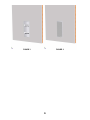
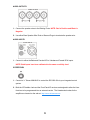
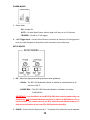
INSTALLATION GUIDE RCC600-SM Subwoofer Module RCC600-SA Subwoofer Amplifier 2 Thank you for choosing Artison’s RCC 600 In-Wall Subwoofer System. We are pleased that you have selected our high-performance audio products. INTRODUCTION The following information will guide you through the installation and setup of your Artison RCC 600 Subwoofer Module and RCC 600 Subwoofer Amplifier. Your RCC600-SM carton should contain the following: 1 . RCC 600 Subwoofer Module 1 . RCC 600 Subwoofer Module Paint Shield 1 . RCC 600 Subwoofer Module Grille 1 . RCC 600 Subwoofer Module Wall Cut-out Template Your RCC600-SA carton should contain the following: 1 . RCC 600 Subwoofer Amplifier 1 . Automatic Room Mode Correction™ (ARMC™) Microphone Kit 2 . Rack-Mount Ears 1 . Remote Control 1 . Detachable IEC Power Cord If you are missing any of these parts or if you need assistance during the installation of your RCC 600, please contact Artison’s Customer Service Department during normal business hours, Pacific Time at (775) 833-4344. 3 RCC 600 SUBWOOFER MODULE (RCC600-SM) The RCC 600 Subwoofer Module can be installed into either an: Artison Pre Build Box (Volume ≈ 1.2 ft3) SOLD SEPERATELY OR Infinite Baffle (i.e. 2x4 stud wall, 16” On Center spacing at least 8 feet tall, Volume 2.8 ft3 or greater) IMPORTANT: In an installation of two RCC600-SM’s that are being powered by one RCC600-SA, both Subwoofer Modules need to be in either Pre Build Boxes or be in Infinite Baffles. You cannot connect two RCC 600 Subwoofer Modules that are in different environments to the same RCC 600 Subwoofer Amplifier. The front of the RCC600-SM and the grille are paintable. The RCC600-SM comes from the factory with a paint-shield attached. When painting the RCC600-SM, ONLY paint the grille and outer edge of the module using the included paint-shield. You will have to tape the shield to the inside face of the baffle to prevent overspray from getting on the foam damping material on the face. DO NOT get paint on the rear of the subwoofer module. Paint can damage the components which would VOID your Warranty. The minimum mounting depth for the RCC600-SM is 3¾” (95.5 mm), i.e. a 2x4 stud is 3½” deep add ¼”, ½” or ⅝” thick drywall and the RCC600-SM will fit. The maximum drywall thickness the RCC600-SM can be mounted in is 1.3125” (33.3 mm). INSTALLATION WITH AN ARTISON Pre Build BOX (Preferred Installation) 1. Please refer to the Installation Guide included in the Artison Pre-Build Box Carton for installation instructions for your Artison Pre-Build Box. 2. Using the speaker wire already run inside the Pre-Build Box manage both the positive and negative conductors through the open tie-wraps on each side of the RCC600-SM. 3. Connect the bare speaker wire ends to the spring-loaded binding posts, manage the speaker wire back, tighten the tie-wraps and trim the excess. 4. Install the RCC600-SM into the pre-cut opening of the Pre-Build Box. See Figure 1. 5. Carefully tighten the six dog leg clamps on the RCC600-SM using the supplied Allen Head wrench. 6. The grille for the RCC600-SM is held in place by magnets. Simply position the grille on the front of the module into the recessed area. See Figure 2. NOTE: While installing the subwoofer module make sure that any excess wire is run 4 properly so that it does not interfere with the driver’s operation. The design of the IW PBB is such that there is NO clearance between the back of the subwoofer module and the back of the PBB. Be careful that no wires are in this area when installing the module INSTALLATION INTO AN INFINITE BAFFLE 1. Use the provided Cut-out Template to mark the desired wall location. Be sure that no piping, wall studs, or electrical wires interfere with the placement of the RCC600-SM. 2. Once the hole is cut and the speaker wire is run, manage both the positive and negative speaker wire conductors through the open tie-wraps on each side of the RCC600-SM. 3. Connect the bare speaker wire ends to the spring-loaded binding posts, manage the speaker wire back, tighten the tie-wraps and trim the excess. 4. Install the RCC600-SM into the pre-cut opening of the Pre-Build Box. See Figure 1. 5. Carefully tighten the six dog leg clamps on the RCC600-SM using the supplied Allen Head wrench. 6. The grille for the RCC600-SM is held in place by magnets. Simply position the grille on the front of the module into the recessed area. See Figure 2. 7. Remove the paint-shield from the front of the RCC600-SM after the installation has been completed NOTE: While installing the subwoofer module ensure any excess wire is run properly so it does not interfere with the driver’s operation. 5 FIGURE 1 FIGURE 2 6 RCC 600 SUBWOOFER AMPLIFIER (RCC600-SA) The RCC 600 Subwoofer Amplifier can be installed into either cabinetry, on an equipment shelf, or it can be rack-mounted into a standard 19” Equipment Rack. In any installation be sure to provide adequate ventilation around the amplifier. The RCC600-SA has two simple and conveniently placed mode settings. The Music Mode or Movie Mode user controls are located on the front panel for selection based on the source material. The Mode settings, Volume and Power Controls of the RCC600-SA can be accessed via IR codes. The remote included with your unit can be downloaded into a learning remote or HEX Codes are available on the Artison Web site. The Front Panel of the RCC600-SA has an IR Receiver and there is a second hard wired feed thru jack that can be connected to an integrated control system on the rear panel. Each control is described in detail below. RACKMOUNT INSTALLATION OF THE RCC600-SA 1. Remove the attached feet of the amplifier. 2. Attach the included rack-mount ears to the front sides of the RCC600-SA. 3. Mount into the 19” equipment rack, the amplifier will occupy 1.5 RU. 4. If installing two RCC600-SA then the rack-mount ears can be flipped to accommodate the two amplifiers in 3 RU. RCC600-SA REMOTE CONTROL The remote control has the following functions: 1. ON/OFF - This will toggle between Standby Mode (Amber Halo) and ON (Blue Halo). 2. MUSIC MODE – This selects the MUSIC MODE EQ. When active it will have a Red Halo added to the Blue Halo. 3. MOVIE MODE – This selects the MUSIC MODE EQ. When active it will have a Red Halo added to the Blue Halo. 4. GAIN – This will raise and lower the volume of the amplifier. A remote or the Gain Knob on the front panel can both be used to raise or lower the bass volume. NOTE: The gain control is configured so that the “last used” device setting will be remembered by the amplifier. 7 RCC600-SA FRONT PANEL CONTROLS GAIN – The position of this knob controls the overall gain (volume) of the subwoofer. Press this button in and it will spring out into a rotating knob, press it back in to hide it. The front panel gain control will become the master gain control until the remote is used. NOTE: The amplifier by default will resume to the last setting by either gain control device. DIM – This button controls the brightness of the Halo lighting on the front panel. There are four brightness settings. POWER – This button will toggle between Standby Mode (Amber Halo) and ON (Blue Halo). MUSIC MODE – This preset EQ mode should be used for music playback. This EQ setting provides a full range of musical bass to enhance the listening experience, when active it will add a Red Halo to the Blue Halo. MOVIE MODE – This preset EQ mode should be used for movie playback. This EQ setting adds more volume and bass to help recreate the true movie theater experience, when active it will add a Red Halo to the Blue Halo. RCC600-SA REAR PANEL AC POWER 1. The Power Switch is the hard ON/OFF power switch for the amplifier. 2. The Red Switch is the input voltage setting; select the appropriate 120V or 230V setting. 3. Connect the detachable IEC Power Cord underneath the Red Voltage Selection Switch. 8 AUDIO OUTPUTS 1. Connect the speaker wires to the Binding Posts. NOTE: Red is Positive and Black is Negative. 2. Use either Bare Speaker Wire Ends or Banana Plugs to terminate the speaker wire. AUDIO INPUTS 1. Connect to either the Balanced Female XLR or Unbalanced Female RCA Inputs. NOTE: Both inputs have been calibrated to the same sensitivity level. IR FEEDTHRU 1. Connect a ⅛” Stereo MINIJACK to control the RCC600-SA via your integrated control system. 2. Both the IR Feedthru Jack and the Front Panel IR receiver are designed to allow the User functions to be programmed into an external remote. The Hexadecimal codes for the amplifier are located on the web at: http://www.artisonusa.com 9 POWER MODES 1. Select either: ON – Always On. AUTO – On with Signal Sense, without signal it will stay on for ≈15 minutes. TRIGGER – On with a 12 Volt trigger. 2. +12V Trigger Input – Use the Green Phoenix Connector to connect a 12 volt trigger wire from your other equipment, the polarity on the connector can be either way. SETUP MODES 1. EQ – Select the appropriate setting based on these guidelines: ∞ Baffle – The RCC 600 Subwoofer Module is installed in a wall that has an air volume of ≥2.8 ft3. CLOSED BOX – The RCC 600 Subwoofer Module is installed in an Artison Pre-Build Box. IMPORTANT: In an installation of two RCC600-SM’s that are being powered by one RCC600-SA, both Subwoofer Modules need to be in either Pre-Build Boxes or be in Infinite Baffles. You cannot connect two RCC 600 Subwoofer Modules that are in different environments to the same RCC 600 Subwoofer Amplifier. 2. PHASE – Comes from the factory set at 0°. The phase of the subwoofer can be adjusted 10 to fine tune the signal coincidence of the subwoofer and the lower frequencies of your LCR Speakers. Adjust the phase listening for an increase in mid bass in the crossover region. A pink-noise generator or an RTA (Real-time Analyzer) can further analyze your installation. 3. LOW PASS – This is the crossover frequency setting of the Low Pass Filter. The RCC600-SA comes from the factory with the 80Hz setting that is recommended for use with the Artison LCR speakers. If used in conjunction with any other speakers consult with the manufacturer for the correct setting for the integration of the subwoofer with the satellites. 4. SLOPE – Select either 12 dB/octave or 24 dB/octave for the slope of the Low Pass Filter based on the correct frequency response at the crossover point. This can be done by measurement or simply listening to the system. A proper crossover will not have an apparent “hole” in the response nor will it exhibit the “bloated” mid bass sound that a peak will create. Again, an RTA can come in handy during this part of the set up. EQ MODES – Automatic Room Mode Correction (ARMC) The amplifier comes from the factory set to BYPASS. This setting produces a flat frequency response at the subwoofer module. In some cases your room response may benefit from ARMC. Eigen-modes, also known as room modes, exist in all rooms. These room modes are an interaction between the listening room itself, the location of the subwoofer, and the low frequency wavelengths being on the same order as the room dimensions. This interaction causes peak and null energy areas in your listening room which differ depending on the room and the subwoofer location. The ARMC program was designed to send a series of tones thru the RCC600-SM and then analyze the system response at the microphone position. The program then reduces the level of the frequency bands that have energy peaks caused by the room modes. As a by product, after the ARMC process has been completed the overall subwoofer amplifier gain may need to be raised to achieve the previous volume levels. If your normal listening position is located in a null, then the only way to truly even out the null is by either moving the subwoofer location to change the room modes that are stimulated OR install a distributed bass system. Distributed bass uses multiple subwoofers in different locations in order to stimulate more of the room modes. It has been shown that this type of system mitigates Eigen-modes and provides a more uniform response to a wider listening area. Each RCC600-SA has the capability for running two RCC600-SM modules. 11 1. AUTO EQ MIC – This is the input jack for the ARMC Microphone. 2. Switch Settings – Select either: a. BYPASS – ARMC not active. b. AUTO EQ. – ARMC active. Will remember the last measured room mode sequence and settings. 3. BLUE LED STATUS INDICATOR a. Continuous Short Flash – Switch in AUTO EQ setting, ARMC not yet saved. Since the amplifier leaves the factory with this function having been tested the LED should not flash continuously even when the switch is set to the AUTO EQ position. NOTE: It is important that you do a room mode set up using the supplied microphone at your listening position if you plan to use the amplifier in this setting b. One Long, Two Short Flashes – Amplifier Error, Shorted Audio Outputs. Remove the amplifier from the wires to the RCC600 SA and use an ohm meter to check for shorts in the line. c. One Long, Three Short Flashes – Over Temperature Indicator. Be sure that the amplifier has adequate ventilation. If the situation continues to exist contact Artison. 4. Calibrate Button – Place the supplied microphone in the desired listening position and plug it into the AUTO EQ MIC input jack. Press the button for a few seconds to initiate ARMC sequence. 12 LIMITED WARRANTY ALL INTERNET SALES ARE STRICTLY PROHIBITED This warranty remains in effect for five years from the date of purchase for speaker products and one year for electronic products. THIS WARRANTY PROTECTS THE ORIGINAL OWNER PROVIDING THAT THE PRODUCT HAS BEEN PURCHASED FROM AN AUTHORIZED ARTISON DEALER IN THE UNITED STATES. THE ORIGINAL BILL OF SALE MUST BE PRESENTED WHENEVER WARRANTY SERVICE IS REQUIRED. FOR WARRANTY SERVICE OUTSIDE THE UNITED STATES, CONTACT THE AUTHORIZED ARTISON DISTRIBUTOR IN THE COUNTRY WHERE THE PRODUCT WAS PURCHASED. Except as specified below, this warranty covers all defects in material and workmanship. The following are not covered: Damage caused by accident, misuse, abuse, product modification or neglect, damage occurring during shipment, damage from failure to follow instructions contained in the Owners Manual, damage resulting from the performance of repairs by someone not authorized by Artison, or any claims based on misrepresentations by the seller. This warranty does not cover incidental or consequential damages. It does not cover the cost of removing or reinstalling the unit. THIS WARRANTY IS VOID IF THE SERIAL NUMBER HAS BEEN REMOVED OR DEFACED, OR IS PURCHASED ON THE INTERNET, WORLD WIDE WEB, MAIL ORDER, 800, 888, 877 TELEPHONE NUMBERS OR THROUGH A CATALOG. This warranty gives you specific legal rights. You may also have other rights, which vary from state to state. Some states do not allow the exclusion or limitation of incidental or consequential damages or limitations on how long an implied warranty lasts, so the above may not apply to you. Please make note of the following information and retain for your record. Product Name________________________ Model Number____________________ Store Name__________________________ Purchase Price____________________ HOW TO OBTAIN SERVICE Please call us at (775) 833-4344, or write to: ARTISON (Attention: Customer Service Department), 774 Mays Blvd., Suite 10-183, Incline Village, NV 89451. We will promptly advise you of what action to take. We may direct you to an authorized Artison Service Center or ask you to send your speaker to the factory for repair. You will need to present the original bill of sale to establish the date of purchase. PLEASE DO NOT SHIP YOUR ARTISON PRODUCT TO THE FACTORY FOR REPAIR WITHOUT PRIOR AUTHORIZATION. PLEASE DO NOT RETURN PRODUCT TO THE ABOVE ADDRESS, IT IS NOT A SERVICE LOCATION. You are responsible for transporting your product for repair and for payment of any initial shipping charges. However, we will pay the return shipping charges if the repairs are covered under warranty. 13