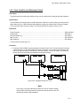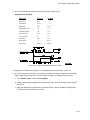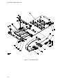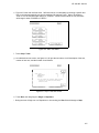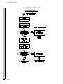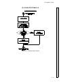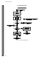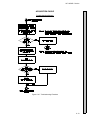
1
About this Manual We’ve added this manual to the Agilent website in an effort to help you support your product. This manual is the best copy we could find; it may be incomplete or contain dated information. If we find a more recent copy in the future, we will add it to the Agilent website. Support for Your Product Agilent no longer sells or supports this product. Our service centers may be able to perform calibration if no repair parts are needed, but no other support from Agilent is available. You will find any other available product information on the Agilent Test & Measurement website, www.tm.agilent.com. HP References in this Manual This manual may contain references to HP or Hewlett-Packard. Please note that Hewlett-Packard's former test and measurement, semiconductor products and chemical analysis businesses are now part of Agilent Technologies. We have made no changes to this manual copy. In other documentation, to reduce potential confusion, the only change to product numbers and names has been in the company name prefix: where a product number/name was HP XXXX the current name/number is now Agilent XXXX. For example, model number HP8648A is now model number Agilent 8648A. SERVICE MANUAL HP 16510B 35 MHz State/ 100 MHz Timing Card ÿ COPYRIGHT HEWLETT-PACKARD COMPANY/COLORADO DIVISION 1989 1900 GARDEN OF THE GODS ROAD, COLORADO SPRINGS, COLORADO U.S.A. ALL RIGHTS RESERVED Manual Part No. 16510-90912 PRINTED: JUNE 1989 HP 16510B - Table of Contents TABLE OF CONTENTS SECTION I General Information 1-1. 1-2. 1-3. 1-4. 1-5. 1-6. 1-7. 1-8. 1-9. Introduction ........................................................................................................................ Modules Covered By This Manual ..................................................................................... Safety Requirements ......................................................................................................... Product Description ............................................................................................................ Accessories Supplied ......................................................................................................... Accessories Available ......................................................................................................... Specifications ...................................................................................................................... Operating Characteristics .................................................................................................. Recommended Test Equipment ........................................................................................ 1-1 1-1 1-1 1-2 1-2 1-2 1-2 1-2 1-2 SECTION II Installation 2-1. 2-2. 2-3. 2-4. 2-5. 2-6. 2-7. 2-8. 2-9. 2-10. 2-11. Introduction ........................................................................................................................ Initial Inspection ................................................................................................................. Preparation For Use ........................................................................................................... Power Requirements ......................................................................................................... Safety Requirements ......................................................................................................... Probe Cable Installation ..................................................................................................... Module Installation ............................................................................................................. Operating Environment ...................................................................................................... Storage .............................................................................................................................. Packaging .......................................................................................................................... Tagging For Service ........................................................................................................... 2-1 2-1 2-1 2-1 2-1 2-1 2-1 2-4 2-4 2-4 2-4 SECTION III Performance Tests 3-1. 3-2. 3-3. 3-4. 3-5. 3-6. 3-7. 3-8. 3-9. 3-10. 3-11. 3-12. 3-13. 3-14. 3-15. Introduction ........................................................................................................................ Recommended Test Equipment ........................................................................................ Test Record ....................................................................................................................... Performance Test Interval .................................................................................................. Performance Test Procedures ........................................................................................... Test Connector .................................................................................................................. Clock, Qualifier, and Data Input Tests 1 ............................................................................ Clock, Qualifier, and Data Input Tests 2 ............................................................................ Clock, Qualifier, and Data Input Tests 3 ............................................................................ Clock, Qualifier, and Data Input Tests 4 ............................................................................ Clock, Qualifier, and Data Input Tests 5 ............................................................................ Clock, Qualifier, and Data Input Tests 6 ............................................................................ Clock, Qualifier, and Data Input Tests 7 ............................................................................ Glitch Test .......................................................................................................................... Threshold Accuracy Test ................................................................................................... 3-1 3-1 3-1 3-1 3-1 3-1 3-2 3-7 3-10 3-13 3-16 3-19 3-22 3-25 3-29 v HP 16510B - Table of Contents SECTION IV Adjustments 4-1. 4-2. 4-3. 4-4. 4-5. 4-6. 4-7. Introduction ......................................................................................................................... 4-1 Calibration Interval .............................................................................................................. 4-1 Safety Requirements .......................................................................................................... 4-1 Recommended Test Equipment ......................................................................................... 4-1 Extender Board Installation................................................................................................. 4-1 Instrument Warmup ............................................................................................................ 4-4 Adjustment And Calibration Check ..................................................................................... 4-4 SECTION V Replaceable Parts 5-1. 5-2. 5-3. 5-4. 5-5. 5-6. Introduction ........................................................................................................................ Abbreviations ..................................................................................................................... Replaceable Parts List ....................................................................................................... Ordering Information .......................................................................................................... Exchange Assemblies ........................................................................................................ Direct Mail Order System ................................................................................................... 5-1 5-1 5-1 5-1 5-1 5-2 SECTION VI Service 6-1. 6-2. 6-3. 6-4. 6-5. 6-6. 6-6. 6-7. 6-8. vi Introduction ........................................................................................................................ Safety Requirements ......................................................................................................... Recommended Test Equipment ........................................................................................ Module Block Diagram And Theory Of Operation............................................................... Self Tests ........................................................................................................................... Troubleshooting Auxiliary Power ........................................................................................ Troubleshooting The HP 16510B ....................................................................................... Module Replacement ......................................................................................................... Probe Assembly Replacement ........................................................................................... 6-1 6-1 6-1 6-1 6-3 6-7 6-7 6-14 6-17 HP 16510B - Table of Contents LIST OF TABLES TABLE TITLE PAGE 1-1. 1-2. 1-3. HP 16510B Specifications .................................................................................................. 1-3 HP 16510B Operating Characteristics ................................................................................ 1-4 Recommended Test Equipment ......................................................................................... 1-9 3-1. Performance Test Record................................................................................................... 3-33 5-1. 5-2. Reference Designations and Abbreviations ........................................................................ 5-3 Replaceable Parts List ........................................................................................................ 5-5 LIST OF FIGURES FIGURE TITLE PAGE 2-1. 2-2. 2-3. Endpate Overlap ................................................................................................................. 2-2 Cable Position..................................................................................................................... 2-3 Endplate Overlap ................................................................................................................ 2-3 3-1. 3-2. 3-3. 3-4. 3-5. 3-6. 3-7. 3-8. 3-9. 3-10. 3-11. 3-12. 3-13. 3-14. 3-15. 3-16. 3-17. 3-18. 3-19. 3-20. 3-21. 3-22. 3-23. 3-24. Test Connector ................................................................................................................... 3-1 Equipment Setup For Test 1 ............................................................................................... 3-2 Pulse Generator Waveform For Test 1 ............................................................................... 3-3 Configuration Screen .......................................................................................................... 3-3 Format Screen For Pod 1 and J Clock Test........................................................................ 3-4 Format Screen / Clock Assignment .................................................................................... 3-4 Format Screen / Bit Assignment ......................................................................................... 3-5 Trace Screen ...................................................................................................................... 3-5 Listing Screen ..................................................................................................................... 3-6 Switching To Next Probe Cable .......................................................................................... 3-6 Equipment Setup For Test 2 ............................................................................................... 3-7 Pulse Generator Waveform For Test 2 ............................................................................... 3-8 Format Screen .................................................................................................................... 3-8 Trace Screen ...................................................................................................................... 3-9 Listing Screen ..................................................................................................................... 3-9 Equipment Setup For Test 3 ............................................................................................... 3-10 Pulse Generator Waveform For Test 3 ............................................................................... 3-11 Listing Screen ..................................................................................................................... 3-12 Equipment Setup For Test 4 ............................................................................................... 3-13 Pulse Generator Waveform For Test 4 ............................................................................... 3-14 Listing Screen ..................................................................................................................... 3-15 Equipment Setup For Test 5 ............................................................................................... 3-16 Pulse Generator Waveform For Test 5 ............................................................................... 3-17 Listing Screen ..................................................................................................................... 3-18 vii HP 16510B - Table of Contents LIST OF FIGURES FIGURE viii TITLE PAGE 3-25. 3-26. 3-27. 3-28. 3-29. 3-30. 3-31. 3-32. 3-33. 3-34. 3-35. 3-36. 3-37. 3-38. 3-39. 3-40. 3-41. 3-42. 3-43. Equipment Setup For Test 6 .............................................................................................. 3-19 Pulse Generator Waveform For Test 6 .............................................................................. 3-20 Format Screen ................................................................................................................... 3-21 Listing Screen .................................................................................................................... 3-21 Equipment Setup For Test 7 .............................................................................................. 3-22 Pulse Generator Waveform For Test 7 .............................................................................. 3-23 Format Screen ................................................................................................................... 3-24 Listing Screen .................................................................................................................... 3-24 Equipment Setup For Glitch Test....................................................................................... 3-25 Pulse Generator Waveform For Glitch Test....................................................................... 3-26 Configuration Screen ......................................................................................................... 3-26 Format Screen ................................................................................................................... 3-27 Trace Screen ..................................................................................................................... 3-27 Listing Screen .................................................................................................................... 3-28 Equipment Setup For Threshold Accuracy ....................................................................... 3-29 Format Screen ................................................................................................................... 3-30 Trace Screen ..................................................................................................................... 3-31 Waveform Screen .............................................................................................................. 3-21 Waveform Screen .............................................................................................................. 3-32 4-1. 4-2. 4-3. 4-4. 4-5. Endplate Overlap ............................................................................................................... 4-2 Extender Board And Module.............................................................................................. 4-3 Adjustment Pot Location .................................................................................................... 4-4 Startup Screen ................................................................................................................... 4-5 Pod Threshold Field ........................................................................................................... 4-5 5-1. Parts Identification .............................................................................................................. 5-4 6-1. 6-2. 6-3. 6-4. 6-5. 6-6. 6-7. 6-8. 6-9. 6-10. 6-11. 6-12. 6-13. 6-14. 6-15. 6-16. 6-17. HP 16510B Module Block Diagram .................................................................................... 6-1 Startup Screen .................................................................................................................... 6-3 Load Test System ............................................................................................................... 6-4 Test System Screen............................................................................................................ 6-4 Main Test Menu .................................................................................................................. 6-5 Chip 1 Test Run Screen...................................................................................................... 6-5 Stop Field............................................................................................................................ 6-6 Exit Test System ................................................................................................................. 6-6 Power And Ground ............................................................................................................. 6-7 Troubleshooting Flowchart.................................................................................................. 6-8 Endplate Overlap ................................................................................................................ 6-14 Cable Position..................................................................................................................... 6-15 Ensplate Overlap ................................................................................................................ 6-16 Endplate Overlap ................................................................................................................ 6-17 Card On Antistatic Mat........................................................................................................ 6-18 Retainer And Screws .......................................................................................................... 6-18 Card Connectors................................................................................................................. 6-19 TABLE OF CONTENTS General Information 1-1. 1-2. 1-3. 1-4. 1-5. 1-6. 1-7. 1-8. 1-9. Introduction......................................................................................................................1-1 Modules Covered By Manual ..........................................................................................1-1 Safety Requirements.......................................................................................................1-1 Product Description .........................................................................................................1-2 Accessories Supplied ......................................................................................................1-2 Accessories Available .....................................................................................................1-2 Specifications ..................................................................................................................1-2 Operating Characteristics ................................................................................................1-2 Recommended Test Equipment......................................................................................1-2 HP 16510B - General Information SECTION I General Information 1-1. Introduction This service manual contains information for testing, adjusting, and servicing the HP 16510B State/Timing Module. Also included are installation procedures and a list of recommended test equipment. This manual is divided into six sections as follows: I- General Information II - Installation III - Performance Tests IV - Adjustments V- Replaceable Parts VI - Service Information for operating, programming, and interfacing the HP 16510B State/Timing Module is contained in the HP 16510B State/Timing Operating and Programming Manual supplied with each module. To complete the service documentation for your system, place this service manual in the 3-ring binder with your Logic Analysis System Service Manual. 1-2. Modules Covered by Manual The information covered in this manual is for the HP 16510B State/Timing Module. 1-3. Safety Requirements Specific warnings, cautions, and instructions are placed wherever applicable throughout the manual. These must be observed during all phases of operation, service, and repair of the module. Failure to comply with them violates safety standards of design, manufacture, and intended use of this module. Hewlett-Packard assumes no liability for the failure of the customer to comply with these safety requirements. The General Information Section includes safety requirements, a product description, and a list of accessories supplied and of accessories available. Also included are tables listing specifications and operating characteristics, and a list of recommended test equipment. 1-1 HP 16510B - General Information • 16 Channel Probe Cable (HP 16510-61601) Qty 3 • Grabbers (Set of 20) (HP 5959-0288) Qty 5 sets • Probe Cable ID Clip (HP 16500-41201) Qty 5 Simultaneous state/state, or simultaneous state/timing analysis. • Probe and Cable Numbering Labels (01650-94303) Time interval; number of states; pattern search; minimum, maximum, and average time interval statistics. • Cable Numbering Labels (16500-94303) • Operating System Disk 1-4. Product Description The HP 16510B State/Timing Module is an 80 channel, 35 MHz state, 100 MHz timing logic analyzer. It can be configured as two independent state analyzers or one state and one timing analyzer. Some of the main features are: • • • Uses transitional timing to store data only when there is a transition. • 5 clock inputs, 4 clock qualifiers, storage qualification, time and number of state tagging, and prestore. • Small lightweight probing. • Configurable to 160 channels wide (HP 16511B). 1-6. Accessories Available • Termination adapter (HP 01650-63201) 1-7. Specifications 1-5. Accessories Supplied The following accessories are supplied with the HP 16510B State/Timing module. Quantity one unless shown otherwise. • Operating and Programming Manual Set • Service Manual • 16 Channel Lead Sets, grey tip (HP 01650-61608) Qty 5 • 16 Channel Probe Cable (HP 16510-61602) Qty 2 1-2 Module specifications are listed in table 1-1. These specifications are the performance standards against which the module is tested. 1-8. Operating Characteristics Table 1-2 is a listing of the module operating characteristics. The operating characteristics are not specifications, but are the typical operating characteristics included as additional information for the user. 1-9. Recommended Test Equipment Equipment required to test and maintain the HP 16510B State/Timing Module is listed in table 1-3. Other equipment may be substituted if it meets or exceeds the critical specifications listed in the table. HP 16510B - General Information Table 1-1. HP 16510B Specifications HP 16510B SPECIFICATIONS Probes Minimum Swing: 600 mV peak-to-peak. Threshold Accuracy: Voltage Range Accuracy -2.0V to +2.0V ±150 mV -9.9V to -2.1V ±300 mV +2.1V to +9.9V ±300 mV State Mode Clock Repetition Rate: Single phase is 35 MHz maximum. With time or state counting, minimum time between states is 60 ns. Both mixed and demultiplexed clocking use master-slave clock timing; master clock must follow slave clock by at least 10 ns and precede the next slave clock by >50 ns. Clock Pulse Width: ≥10 ns at threshold. Setup Time: Data must be present prior to clock transition, ≥ 10 ns. Hold Time: Data must be present after rising clock transition on all pods; 0 ns. Data must be present after falling clock transition on pods 1,3 and 5; 0 ns. Data must be present after falling clock transition on pods 2 and 4; 1 ns. Timing Mode Minimum Detectable Glitch: 5 ns wide at the threshold. 1-3 HP 16510B - General Information Table 1-2. HP 16510B Operating Characteristics HP 16510B OPERATING CHARACTERISTICS Probes Input RC: 100 KΩ ±2% shunted by approximately 8 pF at the probe tip. TTL Threshold Preset: +1.6 volts. ECL Threshold Preset: -1.3 volts. Threshold Range: -9.9 to +9.9 volts in 0.1V increments. Threshold Setting: Threshold levels may be defined for pods 1, 2, and 3 on an individual basis and one threshold may be defined for pods 4 and 5. Dynamic Range: ± 10 volts about the threshold. Minimum Input Overdrive: 250 mV or 30% of the input amplitude, whichever is greater. Maximum Voltage: ±40 volts peak. Measurement Configurations Analyzer Configurations: Analyzer 1 Analyzer 2 Timing Off Off Timing State Off Off State Timing State State Timing State State Off Off Channel Assignment: Each group of 16 channels (a pod) can be assigned to Analyzer 1, Analyzer 2, or remain unassigned. The HP 16510B contains 5 pods. 1-4 HP 16510B - General Information Table 1-2. HP 16510B Operating Characteristics (cont.) State Analysis Memory Data Acquisition: 1024 samples/channel. Trace Specification Clocks: Five clocks are available and can be used by either one or two state analyzers at any time. Clock edges can be ORed together and operate in single phase, two phase demultiplexing, or two phase mixed mode. Clock edge is selectable as positive, negative, or both edges for each clock. Clock Qualifier: The high or low level of up to four clocks can be ANDed with the clock specification. Setup time: 20 ns; hold time: 5 ns. Pattern Recognizers: Each recognizer is the AND combination of bit (0, 1, or X) patterns in each label. Eight pattern recognizers are available when one state analyzer is on. Four are available to each analyzer when two state analyzers are on. Range Recognizers: Recognizes data which is numerically between or on two specified patterns (ANDed combination of 0s and/or 1s). One range term is available and is assigned to the first state analyzer turned on. The maximum size is 32 bits. Qualifier: A user-specified term that can be anystate, nostate, a single pattern recognizer, range recognizer, or logical combination of pattern and range recognizers. Sequence Levels: There are eight levels available to determine the sequence of events required for trigger. The trigger term can occur anywhere in the first seven sequence levels. Branching: Each sequence level has a branching qualifier. When satisfied, the analyzer will restart the sequence or branch to another sequence level. 1-5 HP 16510B - General Information Table 1-2. HP 16510B Operating Characteristics (cont.) Occurrence Counter: Sequence qualifier may be specified to occur up to 65535 times before advancing to the next level. Storage Qualification: Each sequence level has a storage qualifier that specifies the states that are to be stored. Enable/Disable: Defines a window of post-trigger storage. States stored in this window can be qualified. Prestore: Stores two qualified states that precede states that are stored. Tagging State Tagging: Counts the number of qualified states between each stored state. Measurement can be shown relative to the previous state or relative to trigger. Maximum count is 4.4 x 10¹². Time Tagging: Measures the time between stored states, relative to either the previous state or the trigger. Maximum time between states is 48 hours. With tagging on, the acquisition memory is halved; minimum time between states is 60 ns. Symbols Pattern Symbols: User can define a mnemonic for the specific bit pattern of a label. When data display is SYMBOL, mnemonic is displayed where the bit pattern occurs. Bit pattern can include 0s, 1s, and don’t cares. Range Symbols: User can define a mnemonic covering a range of values. Bit pattern for lower and upper limits must be defined as a pattern of 0s and 1s. When data display is SYMBOL, values within the specified range are displayed as mnemonic + offset from base of range. Number of Pattern and Range Symbols: Combined total (both analyzer machines) of 200. Symbols can be down-loaded over RS-232-C. 1-6 HP 16510B - General Information Table 1-2. HP 16510B Operating Characteristics (cont.) Timing Analysis Transitional Timing Mode Sample is stored in acquisition memory only when the data changes. A time tag stored with each sample allows reconstruction of waveform display. Time covered by a full memory acquisition varies with the number of pattern changes in the data. Sample Period: 10 ns. Maximum Time Covered By Data: 5000 seconds. Minimum Time Covered by Data: 10.24 µs. Glitch Capture Mode Data sample and glitch information stored every sample period. Sample Period: 20 ns to 50 ms in a 1-2-5 sequence dependent on s/div and delay settings. Memory Depth: 512 samples/channel. Time Covered by Data: Sample period X 512. Waveform Display Sec/div: 10 ns to 100 s; 0.01% resolution. Delay: -2500 s to 2500 s; presence of data dependent on the number of transitions in data between trigger and trigger plus delay (transitional timing). Accumulate: Waveform display is not erased between successive acquisitions. Overlay Mode: Multiple channels can be displayed on one waveform display line. Primary use is to view summary of bus activity. Maximum Number Of Displayed Waveforms: 24 1-7 HP 16510B - General Information Table 1-2. HP 16510B Operating Characteristics (cont.) Time Interval Accuracy Channel to Channel Skew: 4 ns typical. Time Interval Accuracy: ± (sample period + channel-to-channel skew + 0.01% of time interval reading). Trigger Specification Asynchronous Pattern: Trigger on an asynchronous pattern less than or greater than specified duration. Pattern is the logical AND of specified low, high, or don’t care for each assigned channel. If pattern is valid but duration is invalid, there is a 20 ns reset time before looking for patterns again. Greater Than Duration: Minimum duration is 30 ns to 10 ms with 10 ns or 0.01% resolution, whichever is greater. Accuracy is +0 ns to -20 ns. Trigger occurs at pattern + duration. Less Than Duration: Maximum duration is 40 ns to 10 ms with 10 ns or 0.01% resolution, whichever is greater. Pattern must be valid for at least 20 ns. Accuracy is +20 ns to -0 ns. Trigger occurs at the end of the pattern. Glitch/Edge Triggering: Trigger on glitch or edge following valid duration of asynchronous pattern while the pattern is still present. Edge can be specified as rising, falling or either. Less than duration forces glitch and edge triggering off. 1-8 HP 16510B - General Information Table 1-2. HP 16510B Operating Characteristics (cont.) Measurement and Display Functions Autoscale (Timing Analyzer Only) Autoscale searches for and displays channels with activity on the pods assigned to the timing analyzer. Acquisition Specifications Arming: Each analyzer can be armed by the run key, the other analyzer, or the Intermodule Bus. Trace Mode: Single mode acquires data once per trace specification; repetitive mode repeats single mode acquisitions until stop is pressed or until time interval between two specified patterns is less than or greater than a specified value, or within or not within a specified range. There is only one trace mode when two analyzers are on. Labels Channels may be grouped together and given a six character name. Up to 20 labels in each analyzer may be assigned with up to 32 channels per label. Primary use is for naming groups of channels such as address, data, and control busses. Indicators Activity Indicators: Provided in the Configuration, State Format, and Timing Format menus for identifying high, low, or changing states on the inputs. Markers: Two markers (X and 0) are shown as dashed lines on the display. Trigger: Displayed as a vertical dashed line in the timing waveform display and as line 0 in the state listing display. 1-9 HP 16510B - General Information Table 1-2. HP 16510B Operating Characteristics (cont.) Marker Functions Time Interval: The X and 0 markers measure the time interval between one point on a timing waveform and trigger, two points on the same timing waveform, two points on different waveforms, or two states (time tagging on). Delta States (State Analyzer Only): The X and 0 markers measure the number of tagged states between one state and trigger, or between two states. Patterns: The X and 0 markers can be used to locate the nth occurrence of a specified pattern before or after trigger, or after the beginning of data. The 0 marker can also find the nth occurrence of a pattern before or after the X marker. Statistics: X to 0 marker statistics are calculated for repetitive acquisitions. Patterns must be specified for both markers and statistics are kept only when both patterns can be found in an acquisition. Statistics are minimum X to 0 time, maximum X to 0 time, average X to 0 time, and ratio of valid runs to total runs. Run/Stop Functions Run: Starts acquisition of data in specified trace mode. Stop: In single trace mode or the first run of a repetitive acquisition, STOP halts acquisition and displays the current acquisition data. For subsequent runs in repetitive mode, STOP halts acquisition of data and does not change current display. Data Display/Entry Display Modes: State listing; timing waveforms; interleaved, time-correlated listing of two state analyzers (time tagging on); time-correlated state listing and timing waveform display (state listing in upper half, timing waveform in lower half, and time tagging on). Timing Waveform: Pattern readout of timing waveforms at X or 0 marker. Bases: Binary, Octal, Decimal, Hexadecimal, ASCII (display only), and User-defined symbols. 1-10 HP 16510B - General Information Table 1-2. HP 16510B Operating Characteristics (cont.) Auxiliary Power Power Through Cables: 2/3 amp @ 5V maximum per cable. Current Draw Per Card: 2 amp @ 5V maximum per HP 16510B Operating Environment Temperature: Instrument, 0 ° to 55 ° C (+32 ° to 131 ° F). Probe lead sets and cables, 0 ° to 65 ° C (+32 ° to 149 ° F). Humidity: Instrument, up to 95% relative humidity at +40 ° C (+122 ° F). Altitude: To 4600 m (15,000 ft). Vibration: Operation: Random vibration 5-500 Hz, 10 minutes per axis, ~0.3 g (rms). Non-operating: Random vibration 5-500 Hz, 10 minutes per axis, ~ 2.41 g (rms); and swept sine resonant search, 5-500 Hz, 0.75 g (0-peak), 5 minute resonant dwell @ 4 resonances per axis. 1-11 HP 16510B - General Information Table 1-3. Recommended Test Equipment Instrument Critical Specification Recommended Model Use* DMM 3 1/2 DIGIT RESOLUTION HP 3478A A PULSE GENERATOR 5 ns PULSE WIDTH, 20 ns PERIOD 1.3 ns RISETIME HP 8161A/020 P OSCILLOSCOPE DUAL CHANNEL, 300 MHz BANDWIDTH HP 54201A P POWER SUPPLY + 10.2 V TO - 10.2 V OUTPUT; CURRENT 0-0.4 AMP HP 6216B P 50 OHM FEEDTHRU QTY. 2 HP 10100C P BNC TEE 1 MALE, 2 FEMALE QTY 2 HP 1250-0781 P BNC Cable (M-M) 48 INCH QTY 4 HP 10503A P EXTENDER BOARD NO SUBSTITUTE HP 16500-69004 A TEST CONNECTOR BNC (F) PANEL MOUNT HP 1250-1032 P ∗ 1-12 A = Adjustments P = Performance Tests T = Troubleshooting TABLE OF CONTENTS Installation 2-1. 2-2. 2-3. 2-4. 2-5. 2-6. 2-7. 2-8. 2-9. 2-10. 2-11. 2-1 Introduction .................................................................................................................... 2-1 Initial Inspection ............................................................................................................. 2-1 Preparation For Use ...................................................................................................... 2-1 Power Requirements ..................................................................................................... 2-1 Safety Requirements ..................................................................................................... 2-1 Probe Cable Installation ................................................................................................ 2-1 Module Installation ........................................................................................................ 2-1 Operating Environment ................................................................................................. 2-4 Storage .......................................................................................................................... 2-4 Packaging ...................................................................................................................... 2-4 Tagging For Service ...................................................................................................... 2-4 HP 16510B - Installation SECTION II Installation 2-1. Introduction 2-4. Power Requirements This section explains, how to initially inspect the HP 16510B State/Timing Module, how to prepare it for use, storage and shipment. Also included are procedures for module installation. All power supplies required for operating the HP 16510B State/Timing Module are supplied to the module through the backplane connector. 2-5. Safety Requirements 2-2. Initial Inspection Inspect the shipping container for damage. If the shipping container or cushioning material is damaged, it should be kept until the contents of the shipment have been checked for completeness and the module has been checked mechanically and electrically. The contents of the shipment should be as listed in the "Accessories Supplied" paragraph located in Section 1. Procedures for checking electrical performance are in Section 3. If the contents of the container are incomplete, there is mechanical damage or defect, or the instrument does not pass the performance tests, notify the nearest Hewlett-Packard office. If the shipping container is damaged, or the cushioning material shows signs of stress, notify the carrier as well as the Hewlett-Packard office. Keep the shipping material so the carrier can inspection it. The Hewlett-Packard office will arrange for repair or replacement at Hewlett-Packard’s option without waiting for claim settlement. 2-3. Preparation for Use Read the Safety Considerations in the front of this manual and in Section I before installing or operating this module. Specific warnings, cautions, and instructions are placed wherever applicable throughout the manual. These must be observed during all phases of operation, service, and repair of the module. Failure to comply with them violates safety standards of design, manufacture, and intended use of this module. Hewlett-Packard assumes no liability for the failure of the customer to comply with these safety requirements. 2-6. Probe Cable Installation The HP 16510B State/Timing Module comes with probe cables installed by the factory. If a cable is to be switched or replaced, refer to "Probe Cable Replacement" in Section 6 of this manual. 2-7. Module Installation Do not install, remove or replace the module in the instrument unless the instrument power is turned off. The HP 16510B State/Timing Module will take up one slot in the card cage. For every additional HP 16510B State/Timing Module you install, you will need an additional slot. They may be installed in any slot and in any order. The installation procedure for the module is continued, step-by-step, on the next page. 2-1 HP 16510B - Installation Module Installation (cont.) The effects of ELECTROSTATIC DISCHARGE can damage electronic components. Use grounded wriststraps and mats when you are performing any kind of service to this module. Installation Considerations • The HP 16510B State/Timing Module(s) can be installed in any available card slot and in any order. • Cards or filler panels below the empty slots intended for module installation do not have to be removed. • The probe cables do not have to be removed to install the module. Procedure a. Turn instrument power switch off, unplug power cord and disconnect any input connections. b. Starting from the top, loosen thumb screws on filler panel(s) and card(s). c. Starting from the top, begin pulling card(s) and filler panel(s) out half way. See figure 2-1. Figure 2-1. Endplate Overlap 2-2 HP 16510B - Installation d. Lay the cable(s) flat and pointing out to the rear of the card. See figure 2-2. e. Slide the analyzer card approximately half way into the card cage. f. If you have more analyzer cards to install repeat step d and e. Figure 2-2. Cable Position g. Firmly seat bottom card into backplane connector. Keep applying pressure to the center of card endplate while tightening thumb screws finger tight. h. Repeat for all cards and filler panels in a bottom to top order. See figure 2-3. Figure 2-3. Endplate Overlap i. Any filler panels that are not used should be kept for future use. Filler panels must be installed in all unused card slots for correct air circulation. . 2-3 HP 16510B - Installation 2-8. Operating Environment 2-10. Packaging The operating environment is listed in table 1-2 of Section 1 of this manual. Note should be made of the non-condensing humidity limitation. Condensation within the instrument can cause poor operation or malfunction. Protection should be provided against internal condensation. The following general instructions should be used for repacking the module with commercially available materials. The HP 16510B State/Timing Card will operate at all specifications within the temperature and humidity range given in table 1-2. However, reliability is enhanced when operating the module within the following ranges. • • • Wrap module in anti-static plastic. • Use a strong shipping container. A doublewall carton made of 350 lb. test material is adequate. • Use a layer of shock-absorbing material 70 to 100 mm (3 to 4 inch) thick around all sides of the module to provide firm cushioning and prevent movement inside the container. • Seal shipping container securely. • Mark shipping container FRAGILE to ensure careful handling. • In any correspondence, refer to module by model number and board number. Temperature: +20°C to +35°C (+68°F to +95°F) Humidity: 20% to 80% non-condensing 2-9. Storage The module may be stored or shipped in environments within the following limits: • Temperature: -40°C to +75°C 2-11. Tagging for Service • Humidity: Up to 90% at 65°C • Altitude: Up to 15,300 meters (50,000 feet) If the module is to be shipped to a Hewlett-Packard office for service or repair, attach a tag showing owner (with address), complete board number, and a description of the service required. The module should also be protected from temperature extremes which cause condensation on the module. 2-4 TABLE OF CONTENTS SECTION III Performance Tests 3-1. 3-2. 3-3. 3-4. 3-5. 3-6. 3-7. 3-8. 3-9. 3-10. 3-11. 3-12. 3-13. 3-14. 3-15. Introduction .................................................................................................................... 3-1 Recommended Test Equipment .................................................................................... 3-1 Test Record ................................................................................................................... 3-1 Performance Test Interval ............................................................................................. 3-1 Performance Test Procedures ...................................................................................... 3-1 Test Connector .............................................................................................................. 3-1 Clock, Qualifier, and Data Input Tests 1 ........................................................................ 3-2 Clock, Qualifier, and Data Input Tests 2 ........................................................................ 3-7 Clock, Qualifier, and Data Input Tests 3 ........................................................................ 3-10 Clock, Qualifier, and Data Input Tests 4 ........................................................................ 3-13 Clock, Qualifier, and Data Input Tests 5 ........................................................................ 3-16 Clock, Qualifier, and Data Input Tests 6 ........................................................................ 3-19 Clock, Qualifier, and Data Input Tests 7 ........................................................................ 3-22 Glitch Test ..................................................................................................................... 3-25 Threshold Accuracy Test ............................................................................................... 3-29 HP 16510B - Performance Tests SECTION III Performance Tests 3-1. Introduction 3-5. Performance Test Procedures The procedures in this section test the HP 16510B State/Timing Analyser’s electrical performance using the specifications listed in Section I as the performance standards. All tests can be performed without access to the interior of the instrument. At the end of this section is a form that can be used as a record of performance test results. All performance tests should be performed at the instruments environmental operating temperature and after a 15-minute warm up period. 3-2. Recommended Test Equipment Equipment recommended for performance tests is listed in table 1-3. Any equipment that satisfies the critical specifications given in the table may be substituted for the recommended models. 3-3. Test Record Results of performance tests may be tabulated on the Performance Test Record (table 3-1) at the end of the procedures. The test record lists all of the tested specifications and their acceptable limits. The results recorded on the test record may be used for comparison in periodic maintenance and troubleshooting or after repairs and adjustments have been made. 3-6. Test Connector The performance tests and adjustments require connecting pulse generator outputs to probe pod inputs. Figure 3-1 is a test connector that may be built to allow testing of multiple channels (up to eight at one time). The test connector consists of a BNC connector and a length of wire. Connecting more than eight channels to the test connector at a time will induce loading of the circuit and true signal representation will degrade. Test results may not be accurate if more than eight channels are connected to the test connector. The Hewlett-Packard part number for the BNC connector in figure 3-1 is 1250-1032. An equivalent part may be used in place of the Hewlett-Packard part. 3-4. Performance Test Interval Periodic performance verification of the HP 16510B State/Timing Module is required at two year intervals. The instrument’s performance should be verified after it has been serviced, or if improper operation is suspected. Further checks requiring access to the interior of the instrument are included in the adjustment section, but are not required for the performance verification. Figure 3-1. Test Connector 3-1 HP 16510B - Performance Tests 3-7. Clock, Qualifier, and Data Inputs Test 1 Description: This performance test verifies maximum clock rate with counting mode and the setup and hold times for the falling edge of all clocks to pods 1, 3, and 5. Specification: Clock repetition rate: With time or state counting mode on, minimum time between states is 60 ns. Hold time: Data must be present after falling edge of all clocks; 0 ns. Setup time: Data must be present prior to clock transition;≥ 10ns. Equipment: Pulse Generator.............................................................................................................................HP 8161A/020 Oscilloscope ..................................................................................................................................HP 54201A 50 Ohm Feedthru (2) .....................................................................................................................HP 10100C BNC Tee (2)...................................................................................................................................HP 1250-0781 BNC Cable (4) ...............................................................................................................................HP 10503A Test Connectors (2) see figure 3-1 Procedure: 1. Connect the HP 16510B and test equipment as shown in figure 3-2. Figure 3-2. Equipment Setup For Test 1 Note In this setup, only eight channels are tested at a time to minimize loading. Ground leads must be grounded to ensure accurate test results. Also, the oscilloscope must be high impedence. 3-2 HP 16510B - Performance Tests 2. Set the pulse generator as follows for the output shown in figure 3-3. Setting for the HP 8161A: Parameter Output A Output B Input Mode Norm ---------- Period (PER) 60 ns ---------- Width (WID) 10 ns 10 ns Leading Edge (LEE) 1 ns 1 ns Trailing Edge (TRE) 1 ns 1 ns High Level (HIL) 3.2 V 3.2 V Low Level (LOL) 0V 0V Delay (DEL) 0 ns 0 ns Output Mode Enable Enable Figure 3-3. Pulse Generator Waveform For Test 1 3. Assign the pod under test to Analyzer 1 in the Configuration screen as shown in figure 3-4. Refer to steps a and b if unfamiliar with menus. a. Touch Type field of Analyzer 1, then touch State. b. Touch the Pod field of pod to be tested, then touch Analyzer 1. Figure 3-4. Configuration Screen 3-3 HP 16510B - Performance Tests 4. Assign appropriate clock, a falling edge, a clock period > 60 ns, and bits 0 through 7 of the pod under test to a label in the Format screen as shown in figure 3-5. Refer to steps a and b if unfamiliar with the menus. Figure 3-5. Format Screen for Pod 1 and J Clock Test a. Touch top most Clock field and set appropriate clock for a falling edge. See figure 3-6. Each pod contains one clock line. The clock line on pod 1 is the J clock; the clock line on pod 2 is the K clock; etc. Figure 3-6. Format Screen/Clock Assignment 3-4 HP 16510B - Performance Tests b. Touch the Bit Assignment field and turn on bits 0 through 7 (asterisk (*) = on; dot (.) = off). See figure 3-7. Figure 3-7. Format Screen/Bit Assignment 5. Configure the Trace screen without sequencing levels and set Count to States as shown in figure 3-8. Refer to steps a and b if unfamiliar with the menus. a. Touch Count, then States, then touch Anystate. b. Touch Prestore, then touch Off. Figure 3-8. Trace Screen 3-5 HP 16510B - Performance Tests 6. Touch Run. The State Listing screen will be displayed and should show all F’s for the channels under test. See figure 3-9. Figure 3-9. Listing Screen Note To ensure a consistent pattern of F’s in listing, use Roll field and knob to scroll through State Listing. 7. Connect the next clock line to the test connector and repeat steps 4 and 6. Repeat until all clocks have been tested (clock lines J, K, L, M and N). 8. Remove the pod body (with probe tip assemblies still connected to test connector) from probe cable of pod under test and connect to probe cable of next pod to test. See figure 3-10. Repeat steps 3, 4, 6 and 7 until all pods have been tested (pods 1, 3 and 5). Make sure the appropriate pod and clock are assigned and all probe assemblies are still connected to the test connector. 9. Disconnect lower eight bits from test connector. Attach bits 8 through 15 to test connector and repeat steps 3, 4, 6, 7 and 8 until upper eight bits of all pods have been tested (pods 1, 3 and 5). Figure 3-10. Switching To Next Probe Cable 3-6 HP 16510B - Performance Tests 3-8. Clock, Qualifier, and Data Inputs Test 2 Description: This performance test verifies the setup and hold time specification for the rising edge transition of all clocks. Specification: Setup Time: Data must be present prior to clock transition; ≥10 ns. Hold Time: Data must be present after rising clock transition; 0 ns. Equipment: Pulse Generator.............................................................................................................................HP 8161A/020 Oscilloscope ..................................................................................................................................HP 54201A 50 Ohm Feedthru (2) .....................................................................................................................HP 10100C BNC Tee (2)...................................................................................................................................HP 1250-0781 BNC Cable (4) ...............................................................................................................................HP 10503A Test Connectors (2) see figure 3-1 Procedure: 1. Connect the HP 16510B and test equipment as shown in figure 3-11. Figure 3-11. Equipment Setup For Test 2 Note In this setup, only eight channels are tested at a time to minimize loading. Ground leads must be grounded to ensure accurate test results. Also, the oscilloscope must be high impedence. 3-7 HP 16510B - Performance Tests 2. Set the pulse generator as follows for the output shown in figure 3-12. Setting for the HP 8161A: Parameter Output A Output B Input Mode Norm ---------- Period (PER) 28.6 ns ---------- Width (WID) 18.6 ns 18.6 ns Leading Edge (LEE) 1 ns 1 ns Trailing Edge (TRE) 1 ns 1 ns High Level (HIL) 3.2 V 3.2 V Low Level (LOL) 0V 0V Delay (DEL) 0 ns 0 ns Output Mode Enable Enable Figure 3-12. Pulse Generator Waveform For Test 2 3. Assign the pod under test to Analyzer 1 in the Configuration screen as shown in figure 3-4. 4. Assign appropriate clock, a rising edge, a clock period < 60 ns, and bits 0 through 7 of the pod under test to a label in the Format screen as shown in figure 3-13. Figure 3-13. Format Screen 3-8 HP 16510B - Performance Tests 5. Configure the Trace screen without sequencing levels and set Count to Off as shown in figure 3-14. Figure 3-14. Trace Screen 6. Touch Run. The State Listing screen will be displayed and should show all 0’s for the channels under test. See figure 3-15. Figure 3-15. Listing Screen Note To ensure a consistent pattern of 0’s in listing, use Roll field and knob to scroll through State Listing. 7. Connect the next clock line to the test connector and repeat steps 4 and 6. Repeat until all clocks have been tested (clock lines J, K, L, M and N). 8. Remove the pod body (with probe tip assemblies still connected to test connector) from probe cable of pod under test and connect to probe cable of next pod to test. See figure 3-10. Repeat steps 3, 4, 6 and 7 until all pods have been tested (pods 1 through 5). Make sure the appropriate pod and clock are assigned and all probe assemblies are still connected to the test connector. 9. Disconnect lower eight bits from test connector. Attach bits 8 through 15 to test connector and repeat steps 3, 4, 6, 7 and 8 until upper eight bits of all pods have been tested (pods 1 through 5). 3-9 HP 16510B - Performance Tests 3-9. Clock, Qualifier, and Data Inputs Test 3 Description: This performance test verifies the hold time specifications for the falling clock transitions of all clocks to pods 2 and 4. Specification: Hold Time: Data must be present after falling clock transitions; 1 ns. Equipment: Pulse Generator.............................................................................................................................HP 8161A/020 Oscilloscope ..................................................................................................................................HP 54201A 50 Ohm Feedthru (2) .....................................................................................................................HP 10100C BNC Tee (2)...................................................................................................................................HP 1250-0781 BNC Cable (4) ...............................................................................................................................HP 10503A Test Connectors (2) see figure 3-1 Procedure: 1. Connect the HP 16510B and test equipment as in figure 3-16. Figure 3-16. Equipment Setup For Test 3 Note In this setup, only eight channels are tested at a time to minimize loading. Ground leads must be grounded to ensure accurate test results. Also, the oscilloscope must be high impedence. 3-10 HP 16510B - Performance Tests 2. Set the pulse generator as follows for the output shown in figure 3-17. Setting for the HP 8161A: Parameter Output A Output B Input Mode Norm ---------- Period (PER) 57.2 ns ---------- Width (WID) 11 ns 10 ns Leading Edge (LEE) 1 ns 1 ns Trailing Edge (TRE) 1 ns 1 ns High Level (HIL) 3.2 V 3.2 V Low Level (LOL) 0V 0V Delay (DEL) 0 ns 0 ns Double Pulse ---------- 28.6 ns Output Mode Enable Enable Figure 3-17. Pulse Generator Waveform For Test 3 3. Assign the pod under test to Analyzer 1 in the Configuration screen as in previous test figure 3-4. 4. Assign appropriate clock, a falling edge, clock period < 60 ns, and bits 0 through 7 of the pod under test to a label in the Format screen. See figure 3-13. 5. Configure the Trace screen without sequencing levels and set Count to Off as shown in figure 3-14. 3-11 HP 16510B - Performance Tests 6. Touch Run. The State Listing screen will be displayed and should list alternate F’s and 0’s as shown in figure 3-18. Figure 3-18. Listing Screen Note To ensure a consistent pattern of alternating F’s and 0’s, use the Roll field and knob to scroll through the State Listing. 7. Connect the next clock line to the test connector and repeat steps 4 and 6. Repeat until all clocks have been tested (clocks lines J, K, L, M and N). 8. Remove the pod body (with probe tip assemblies still connected to test connector) from probe cable of pod under test and connect to probe cable of next pod to test. See figure 3-10. Repeat steps 3, 4, 6 and 7 until all pods have been tested (pods 2 and 4). Make sure the appropriate pod and clock are assigned and all probe assemblies are still connected to the test connector. 9. Disconnect lower eight bits from test connector. Attach bits 8 through 15 to test connector and repeat steps 3, 4, 6, 7 and 8 until upper eight bits of all pods have been tested (pods 2 and 4). 3-12 HP 16510B - Performance Tests 3-10. Clock, Qualifier, and Data Inputs Test 4 Description: This performance test verifies maximum clock rate with counting mode and the setup times for the falling edge of all clocks to pods 2 and 4. Specification: Clock repetition rate: With time or state counting mode on, minimum time between states is 60 ns. Setup time: Data must be present prior to clock transition, ≥ 10ns. Equipment: Pulse Generator.............................................................................................................................HP 8161A/020 Oscilloscope ..................................................................................................................................HP 54201A 50 Ohm Feedthru (2) .....................................................................................................................HP 10100C BNC Tee (2)...................................................................................................................................HP 1250-0781 BNC Cable (4) ...............................................................................................................................HP 10503A Test Connectors (2) see figure 3-1 Procedure: 1. Connect the HP 16510B and test equipment as in figure 3-19. Figure 3-19. Equipment Setup For Test 4 Note In this setup, only eight channels are tested at a time to minimize loading. Ground leads must be grounded to ensure accurate test results. Also, the oscilloscope must be high impedence. 3-13 HP 16510B - Performance Tests 2. Set the pulse generator as follows for the output shown in figure 3-20. Setting for the HP 8161A: Parameter Output A Output B Input Mode Norm ---------- Period (PER) 60 ns ---------- Width (WID) 11 ns 10 ns Leading Edge (LEE) 1 ns 1 ns Trailing Edge (TRE) 1 ns 1 ns High Level (HIL) 3.2 V 3.2 V Low Level (LOL) 0V 0V Delay (DEL) 0 ns 0 ns Output Mode Enable Enable Figure 3-20. Pulse Generator Waveform For Test 4 3. Assign the pod under test to Analyzer 1 in the Configuration screen as in previous test figure 3-4. 4. Assign appropriate clock, a falling edge, clock period > 60 ns, and bits 0 through 7 of the pod under test to a label in the Format screen. See figure 3-5. 5. Configure the Trace screen without sequencing levels and set Count to States. See figure 3-8. 3-14 HP 16510B - Performance Tests 6. Touch Run. The State Listing screen will be displayed and should list all F’s as shown in figure 321. Figure 3-21. Listing Screen Note To ensure a consistent pattern of F’s in the listing, use the Roll field and knob to scroll through the State Listing. 7. Connect the next clock line to the test connector and repeat steps 4 and 6. Repeat until all clocks have been tested (clocks lines J, K, L, M and N). 8. Remove the pod body (with probe tip assemblies still connected to test connector) from probe cable of pod under test and connect to probe cable of next pod to test. See figure 3-10 . Repeat steps 3, 4, 6 and 7 until all pods have been tested (pods 2 and 4). Make sure the appropriate pod and clock are assigned and all probe assemblies are still connected to the test connector. 9. Disconnect lower eight bits from test connector. Attach bits 8 through 15 to test connector and repeat steps 3, 4, 6, 7 and 8 until upper eight bits of all pods have been tested (pods 2 and 4). 3-15 HP 16510B - Performance Tests 3-11. Clock, Qualifier, and Data Inputs Test 5 Description: This performance test verifies the minimum swing voltages of the input probes and the maximum clock rate of the HP 16510B when it is in single phase mode. Specification: Minimum swing: 600 mV peak-to-peak. Clock repetition rate: Single phase is 35 MHz maximum. Clock pulse width: ≥ 10 ns at threshold. Equipment: Pulse Generator ............................................................................................................................HP 8161A/020 Oscilloscope .................................................................................................................................HP 54201A 50 Ohm Feedthru (2) ....................................................................................................................HP 10100C BNC Cable (2) ...............................................................................................................................HP 10503A Test Connectors (2) see figure 3-1 Procedure: 1. Connect the HP 16510B and test equipment as in figure 3-22. In order to most accurately measure the amplitude of the test signals from the pulse generator, high impedance scope probes should be used to look at the signal levels at the output of the BNC test connector. Figure 3-22. Equipment Setup For Test 5 Note In this setup, only eight channels are tested at a time to minimize loading. Ground leads must be grounded to ensure accurate test results. Also, the oscilloscope must be high impedence. 3-16 HP 16510B - Performance Tests 2. Set the pulse generator as follows for the output shown in figure 3-23. Setting for the HP 8161A: Parameter Output A Output B Input Mode Norm ---------- Period (PER) 57.2 ns ---------- Width (WID) 20 ns 10 ns Leading Edge (LEE) 1 ns 1 ns Trailing Edge (TRE) 1 ns 1 ns High Level (HIL) 1.9 V 1.9 V (see Note below) Low Level (LOL) 1.3 V 1.3 V (see Note below) Delay (DEL) 18.6 ns 0 ns Double Pulse ---------- 28.6 ns Output Mode Enable Enable Figure 3-23. Pulse Generator Waveform For Test 5 Note The voltage levels of the waveforms must have the correct amplitude at the logic analyzer probe tips. The pulse generator output may have to be increased slightly to compensate for the loading by the logic analyzer. 3. Assign the pod under test to Analyzer 1 in the Configuration screen as shown in figure 3-4. 4. Assign appropriate clock, a rising edge, clock period < 60 ns, and bits 0 through 7 of the pod under test to a label in the Format screen. See figure 3-13. 5. Configure the Trace screen without sequencing levels and set Count to Off. See figure 3-14. 3-17 HP 16510B - Performance Tests 6. Touch Run. The State Listing screen will be displayed and should list alternating F’s and 0’s as shown in figure 3-24. Figure 3-24. Listing Screen Note To ensure a consistent pattern of alternating F’s and 0’s, use the Roll field and knob to scroll through the State Listing. 7. Connect the next clock line to the test connector and repeat steps 4 and 6. Repeat until all clocks have been tested (clocks lines J, K, L, M and N). 8. Remove pod body (with probe tip assemblies still connected to test connector) from probe cable of pod under test and connect to probe cable of next pod to test. See figure 3-10. Repeat steps 3, 4, 6 and 7 until all pods have been tested (pods 1 through 5). Make sure the appropriate pod and clock are assigned and all probe assemblies are still connected to the test connector. 9. Disconnect lower eight bits from test connector. Attach bits 8 through 15 to test connector and repeat steps 3, 4, 6, 7 and 8 until upper eight bits of all pods have been tested (pods 1 through 5). 3-18 HP 16510B - Performance Tests 3-12. Clock, Qualifier, and Data Inputs Test 6 Description: This performance test verifies the maximum clock rate for mixed mode clocking during state operation. Specification: Clock repetition rate: Single phase is 35 MHz maximum. With time or state counting, minimum time between states is 60 ns. Both mixed and demultiplexed clocking use master-slave clock timing; master clock must follow slave clock by at least 10 ns and precede the next slave clock by > 50 ns. Equipment: Pulse Generator.............................................................................................................................HP 8161A/020 Oscilloscope ..................................................................................................................................HP 54201A 50 Ohm Feedthru (2) .....................................................................................................................HP 10100C BNC Tee (2)...................................................................................................................................HP 1250-0781 BNC Cable (4) ...............................................................................................................................HP 10503A Test Connectors (2) see figure 3-1 Procedure: 1. Connect the HP 16510B and test equipment as shown in figure 3-25. Connect channels 0 through 3 and 8 through 11 of the pod under test to the test connector. On the slave clock transition, the four bits of the lower byte are transferred to the logic analyzer, and on the master clock transition, the four bits of the upper byte are transferred to the logic analyzer. Figure 3-25. Equipment Setup For Test 6 Note In this setup, only eight channels are tested at a time to minimize loading. Ground leads must be grounded to ensure accurate test results. Also, the oscilloscope must be high impedence. 3-19 HP 16510B - Performance Tests 2. Set the pulse generator as follows for the output shown in figure 3-26. Setting for the HP 8161A: Parameter Output A Output B Input Mode Norm ---------- Period (PER) 120 ns ---------- Width (WID) 60 ns 10 ns Leading Edge (LEE) 1 ns 1 ns Trailing Edge (TRE) 1 ns 1 ns High Level (HIL) 3.2 V 3.2 V Low Level (LOL) 0V 0V Delay (DEL) 40 ns 0 ns Double Pulse ---------- 60 ns Output Mode Enable Enable Figure 3-26. Pulse Generator Waveform For Test 6 3. Assign the pod under test to Analyzer 1 in the Configuration screen as shown in figure 3-4. 4. Set up Format screen as in figure 3-27, assigning a falling clock edge as master clock and rising edge of same clock as slave clock. Refer to steps a through c if unfamiliar with the menus. a. Touch lower Clock field, then touch Mixed Clocks. b. Assign falling edge of the appropriate clock as master clock and rising edge of the same clock as slave clock. c. Assign the appropriate eight bits of pod under test (channels 0-3 and 8-11, or 4-7 and 12-15). The clock period should be set to < 60 ns. 3-20 HP 16510B - Performance Tests Figure 3-27. Format Screen 5. Configure Trace screen without sequencing levels and set Count to Off. See figure 3-14. 6. Touch Run. The State Listing screen will be displayed and should list alternating F’s and 0’s as shown in figure 3-28. Figure 3-28. Listing Screen Note To ensure a consistent pattern of alternating F’s and 0’s, use the Roll field and knob to scroll through the State Listing. 7. Connect the next clock line to the test connector and repeat steps 4 and 6. Repeat until all clocks have been tested (clocks lines J, K, L, M and N). 8. Remove pod body (with probe tip assemblies still connected to test connector) from probe cable of pod under test and connect to probe cable of next pod to test. See figure 3-10. Repeat steps 3, 4, 6 and 7 until all pods have been tested (pods 1 through 5). Make sure the appropriate pod and clock are assigned and all probe assemblies are still connected to the test connector. 9. Disconnect bits 0-3 and 8-11 from test connector. Attach bits 4-7 and bits 12-15 to test connector and repeat steps 3, 4, 6, 7 and 8 until all pods have been tested (pods 1 through 5). 3-21 HP 16510B - Performance Tests 3-13. Clock, Qualifier, and Data Inputs Test 7 Description: This performance test verifies the maximum clock rate for demultiplexed clocking during state operation. Specification: Clock repetition rate: Single phase is 35 MHz maximum. With time or state counting, minimum time between states is 60 ns. Both mixed and demultiplexed clocking use master-slave clock timing; master clock must follow slave clock by at least 10 ns and precede the next slave clock by > 50 ns. Equipment: Pulse Generator.............................................................................................................................HP 8161A/020 Oscilloscope ..................................................................................................................................HP 54201A 50 Ohm Feedthru (2) .....................................................................................................................HP 10100C BNC Tee (2)...................................................................................................................................HP 1250-0781 BNC Cable (4) ...............................................................................................................................HP 10503A Test Connectors (2) see figure 3-1 Procedure: 1. Connect the HP 16510B and test equipment as shown in figure 3-29 by connecting channels 0 - 7 of the pod under test to test connector. During demultiplexed clocking only the lower eight bits of each pod are used. Figure 3-29. Equipment Setup For Test 7 Note In this setup, only eight channels are tested at a time to minimize loading. Ground leads must be grounded to ensure accurate test results. Also, the oscilloscope must be high impedence. 3-22 HP 16510B - Performance Tests 2. Set the pulse generator as follows for the output shown in figure 3-30. Setting for the HP 8161A: Parameter Output A Output B Input Mode Norm ---------- Period (PER) 120 ns ---------- Width (WID) 60 ns 10 ns Leading Edge (LEE) 1 ns 1 ns Trailing Edge (TRE) 1 ns 1 ns High Level (HIL) 3.2 V 3.2 V Low Level (LOL) 0V 0V Delay (DEL) 40 ns 0 ns Double Pulse ---------- 60 ns Output Mode Enable Enable Figure 3-30. Pulse Generator Waveform For Test 7 3. Assign the pod under test to Analyzer 1 in Configuration screen as shown in figure 3-4. 4. Set up Format screen as in figure 3-31, assigning a falling clock edge as master clock and rising edge of same clock as slave clock. Refer to steps a through c if unfamiliar with the menus. a. Touch Master | Slave , then touch Demultiplex. b. Assign a falling edge of appropriate as master clock and a rising clock edge of same clock as slave clock. c. Assign all channels to pod under test (only bits 0 through 7 will be available for assignment). The Clock Period should be set to < 60 ns. 3-23 HP 16510B - Performance Tests Figure 3-31. Format Screen 5. Configure Trace screen without sequencing levels and set Count to Off as shown in figure 3-14. 6. Touch Run. The State Listing screen will be displayed and should list alternating F’s and 0’s as shown in figure 3-32. Figure 3-32. Listing Screen Note To ensure a consistent pattern of alternating F’s and 0’s, use the Roll field and knob to scroll through the State Listing. 7. Connect the next clock line to the test connector and repeat steps 4 and 6. Repeat until all clocks have been tested (clocks lines J, K, L, M and N). 8. Remove pod body (with probe tip assemblies still connected to the test connector) from probe cable of pod under test and connect to probe cable of next pod to test. See figure 3-10. Repeat steps 3, 4, 6 and 7 until all pods have been tested (pods 1 through 5). Make sure the appropriate pod and clock are assigned. 3-24 HP 16510B - Performance Tests 3-14. Glitch Test Description: This performance test verifies the glitch detection specification. Specification: Minimum detectable glitch: 5 ns wide at the threshold. Equipment: Pulse Generator.............................................................................................................................HP 8161A/020 Oscilloscope ..................................................................................................................................HP 54201A 50 Ohm Feedthru...........................................................................................................................HP 10100C BNC Tee .......................................................................................................................................HP 1250-0781 BNC Cable (2) ...............................................................................................................................HP 10503A Test Connector (1) see figure 3-1 Procedure: 1. Connect the HP 16510B and test equipment as shown in figure 3-33. The clock inputs are not used for the glitch performance test. Using the oscilloscope, make sure the pulses are 5 ns wide at the threshold (1.6V). Figure 3-33. Equipment Setup For Glitch Test Note In this setup, only eight channels are tested at a time to minimize loading. Ground leads must be grounded to ensure accurate test results. Also, the oscilloscope must be high impedence. 3-25 HP 16510B - Performance Tests 2. Set the pulse generator as follows for the output shown in figure 3-34. Setting for the HP 8161A: Parameter Output A Output B Input Mode Norm ---------- Period (PER) 20 ns ---------- Width (WID) 5 ns ---------- Leading Edge (LEE) 1 ns ---------- Trailing Edge (TRE) 1 ns ---------- High Level (HIL) 3.2 V ---------- Low Level (LOL) 0V ---------- Delay (DEL) 0 ns ---------- Output Mode Enable ---------- Figure 3-34. Pulse Generator Waveform For Glitch Test 3. Assign the pod under test to Analyzer 1 in the Configuration Screen as shown in figure 3-35. Refer to steps a and b if unfamiliar with menus. a. Touch Type field of analyzer 1 and set to Timing. b. Touch pod to be tested and assign to Machine 1. Figure 3-35. Configuration Screen 3-26 HP 16510B - Performance Tests 4. Assign the appropriate eight bits of the pod under test in the Bit Assignment field, then assign the pod to a label in the Format screen as shown in figure 3-36. Figure 3-36. Format Screen 5. Configure Trace screen as shown in figure 3-37. Follow steps a through c if unfamiliar with menus. a. Set Acquisition mode to Glitch. b. Set Find Pattern to all DON’T CARE (X’s) and present for > 30 ns. c. Set Then find Glitch on all channels (all *’s). Figure 3-37. Trace Screen 3-27 HP 16510B - Performance Tests 6. Touch Run, then drag finger to Single. The timing analyzer will acquire data and show glitches for channels under test as shown in figure 3-38. Select the Delay field and spin knob to ensure consistent glitch detection. Figure 3-38. Listing Screen Note If sample clock and data synchronize, glitches may be displayed on the Timing screen as valid data transitions. 7. Remove pod body (with probe tip assemblies still connected to test connector) from probe cable of pod under test and connect to probe cable of next pod to test. See figure 3-10. Repeat steps 3, 4 and 6 until all pods have been tested (pods 1 through 5). Make sure the pod to be tested is assigned in the Configuration screen. 8. Disconnect lower eight bits from test connector. Attach upper eight bits to test connector and repeat steps 3, 4, 6 and 7 until the upper eight bits of all pods have been tested (pods 1 through 5). 3-28 HP 16510B - Performance Tests 3-15. Threshold Accuracy Test Description: This performance test verifies the threshold accuracy within the three ranges stated in the specification. Specification: Threshold accuracy: 150 mV accuracy over the range -2.0 to +2.0 volts; 300 mV accuracy over the ranges -9.9 to -2.1 volts and +2.1 to +9.9 volts. Equipment: Power Supply ................................................................................................................................HP 6216B BNC Cable ....................................................................................................................................HP 10503A Test Connector (1) see figure 3-1 Procedure: 1. Connect the HP 16510B and test equipment as shown in figure 3-39. Figure 3-39. Equipment Setup For Threshold Accuracy Note In this setup, only eight channels are tested at a time to minimize loading. Ground leads must be grounded to ensure accurate test results. 3-29 HP 16510B - Performance Tests 2. Assign the pod under test to Analyzer 1 in the Configuration screen as shown in figure 3-35. 3. Configure the Format screen for User Defined pod threshold of 0.0 V for the pod under test and assign the appropriate eight bits in the Bit Assignment field as shown in figure 3-40. Refer to steps a and b if unfamiliar with menus. a. Touch the Pod Threshold field, then touch User defined and assign appropriate threshold voltage. b. Touch the Bit Assignment field and turn on appropriate eight bits to be tested (* = on; . = off). Figure 3-40. Format Screen 3-30 HP 16510B - Performance Tests 4. Configure Trace screen as shown in figure 3-41. Follow steps a through c if unfamiliar with menus. a. Set Acquisition mode to Glitch. b. Set Find Pattern to all DON’T CARE (x’s) and present for > 30 ns. c. Set Then find Glitch to all OFFs (.’s). Figure 3-41. Trace Screen 5. Adjust the power supply output for +150 mV. 6. Touch Run, then drag finger to Single. Data displayed on Waveform screen should be high for the pod under test. See figure 3-42. Figure 3-42. Waveform Screen 3-31 HP 16510B - Performance Tests 7. Adjust power supply for output of -150 mV. 8. Touch Run. Data displayed on the Waveform screen should be all low for the channels under test as shown in figure 3-43. Figure 3-43. Waveform Screen 9. Return to the Format screen and change User defined Pod Threshold to +9.9 V. 10. Adjust power supply for output of +10.2 V. 11. Touch Run. Data displayed on the Waveform screen should be all high for the pod under test as in previous figure 3-42. 12. Adjust power supply for output of +9.6 V. 13. Touch Run. Data displayed on the Waveform screen should be all low as in previous figure 3-43. 14. Return to the Format screen and change the User defined Pod Threshold to -9.9 V. 15. Adjust power supply for output of -9.6 V. 16. Touch Run. Data displayed in the Waveform screen should be all high for pod under test as in figure 3-42. 17. Adjust power supply for output of -10.2 V. 18. Touch Run. Data displayed in the Waveform screen should be all low for pod under test as in figure 3-43. 19. Remove pod body (with probe tip assemblies still connected to test connector) from probe cable of pod under test and connect to probe cable of next pod to test. See figure 3-10. Repeat steps 2 through 18 until all pods have been tested (pods 1 through 5). 20. Disconnect lower eight bits from test connector. Attach bits 0 through 7 to test connector and repeat steps 2 through 19 until the upper eight bits of all pods have been tested (pods 1 through 5). 3-32 HP 16510B - Performance Tests Table 3-1. Performance Test Record Hewlett-Packard Tested By Model 16510B Work Order No. State/Timing Card Date Tested Calibration Interval Paragraph 3-7 24 Months Board No. Test Results Clock, Qualifier, and Data Inputs Test 1 Passed Failed Passed Failed Passed Failed Passed Failed Passed Failed Pod 1 Pod 3 Pod 5 3-8 Clock, Qualifier, and Data Inputs Test 2 Pod 1 Pod 2 Pod 3 Pod 4 Pod 5 3-9 Clock, Qualifier, and Data Inputs Test 3 Pod 2 Pod 4 3-10 Clock, Qualifier, and Data Inputs Test 4 Pod 2 Pod 4 3-11 Clock, Qualifier, and Data Inputs Test 5 Pod 1 Pod 2 Pod 3 Pod 4 Pod 5 3-33 HP 16510B - Performance Tests Table 3-1. Performance Test Record Paragraph 3-12 Test Results Clock, Qualifier, and Data Inputs Test 6 Passed Failed Passed Failed Passed Failed Passed Failed Pod 1 Pod 2 Pod 3 Pod 4 Pod 5 3-13 Clock, Qualifier, and Data Inputs Test 7 Pod 1 Pod 2 Pod 3 Pod 4 Pod 5 3-14 Glitch Test Pod 1 Pod 2 Pod 3 Pod 4 Pod 5 3-15 Threshold Accuracy Test Pod 1 Pod 2 Pod 3 Pod 4 Pod 5 3-34 TABLE OF CONTENTS Adjustments 4-1. 4-2. 4-3. 4-4. 4-5. 4-6. 4-7. 4-1 Introduction......................................................................................................................4-1 Calibration Interval ..........................................................................................................4-1 Safety Requirements.......................................................................................................4-1 Recommended Test Equipment......................................................................................4-1 Extender Board Installation .............................................................................................4-1 Instrument Warmup.........................................................................................................4-4 Adjustment And Calibration Check..................................................................................4-4 HP 16510B - Adjustments SECTION IV Adjustments 4-1. Introduction 4-3. Safety Requirements This section provides information on when to calibrate the module and how to calibrate, adjust and warm up the module. Also included in this section are equipment setups, a list of recommended test equipment and a procedure for installation of the extender board. Specific warnings, cautions, and instructions are placed wherever applicable throughout the manual. These must be observed during all phases of operation, service, and repair of the module. Failure to comply with them violates safety standards of design, manufacture, and intended use of this module. Hewlett-Packard assumes no liability for the failure of the customer to comply with these safety requirements. 4-2. Calibration Interval To maintain proper operation of the HP 16510B State/Timing Module, calibration should be performed at approximately two year intervals when the instrument is being used under normal operating conditions. If the instrument is used more than one shift per day, it may have to be calibrated more often. New modules are preadjusted at the factory to meet the specifications listed in Section 1 of this manual. Before any adjustments are made to the module, the performance tests in Section III should be done. If the performance tests are within specifications, then adjustments are not necessary. If adjustments are necessary, refer to the safety summary at the front of this manual. 4-4. Recommended Test Equipment Recommended adjustment test equipment is listed in table 1-3. Any equipment that satisfies the critical specifications given in the table may be substituted for the recommended models. 4-5. Extender Board Installation Before any adjustments or calibration checks are done, the HP 16510B Card must be installed on an extender board. The procedure for this installation is on the next page. 4-1 HP 16510B - Installation Extender Board Installation (cont.) The effects of ELECTROSTATIC DISCHARGE can damage electronic components. Grounded wriststraps and mats should be used when performing any kind of service to this module. Installation Considerations • Any empty slot may be used in the card cage. • If there are other modules installed in the card cage, it will be easier to use the same slot that the HP 16510B card came out of. • Cards or filler panels below the slot intended for extender board installation do not have to be removed. Procedure a. Turn instrument power switch off, unplug power cord and disconnect any input connections. b. Starting from the top, loosen thumb screws on filler panel(s) and card(s). c. Starting from the top, begin pulling card(s) and filler panel(s) out half way. See figure 4-1. Figure 4-1. Endplate Overlap d. Pull card to be serviced, completely out. e. Push all other cards back into card cage, but not completely in, so they won’t be in the way for extender board installation. 4-2 HP 16510B - Installation f. Slide extender board completely into card cage making sure it is firmly seated in backplane connecter. g. Plug HP 16510B card into extender board. See figure 4-2. Figure 4-2. Extender Board And Module 4-3 HP 16510B - Installation 4-6. Instrument Warmup Adjustments or calibration checks should be performed at the instruments environmental ambient temperature and after a 15 minute warm-up. 4-7. Adjustment and Calibration Check There is one calibration check on the HP 16510B card. If calibration is out, there will be one adjustment to make. This adjustment is preset at the factory and normally should not need adjustment. If, after referring to the section "Performance Test Interval," the reference voltage is suspected as a problem, perform the following procedure. Description This procedure will check and adjust the +5 Volt reference for the D/A converter. Equipment DMM ..............................................................................................................................................HP 3478A Procedure a. Connect the positive lead from the multimeter to the TP and the negative lead to the TP GND. For the location of the test points and the adjustable resistor, refer to figure 4-3. Figure 4-3. Adjustment Pod Location 4-4 HP 16510B - Installation b. Select a range on the multimeter that will measure as close to +5.000 Volts as possible. c. From the startup screen shown in figure 4-4, touch these fields in the ordered sequence below: 1. System 2. State/Timing (If multiple HP 16510B cards, pick one to be adjusted) 3. Configuration 4. Format Figure 4-4. Startup Screen d. Touch the pod A1 threshold field labeled TTL. See figure 4-5. Figure 4-5. Pod Threshold Field e. Touch User and set threshold to +9.9 Volts, then touch Done. 4-5 HP 16510B - Installation f. With a non-metallic adjustment tool, adjust the variable resistor R76 until the multimeter reads 0.99 Volts (± 0.001 V). g. Set user defined threshold level to -9.9 Volts. h. Read the voltage displayed and note the difference between this reading and -0.99 Volts. Adjust R76 so this difference in halved (± 0.001 V). Examples: If reading is + 0.95 V, the difference is .04 V. Adjust R76 for + 0.97 V. If reading is + 0.97 V, the difference is .02 V. Adjust R76 for + 0.98 V. i. Turn instrument off and unplug the power cord. j. Disconnect test equipment and remove the HP 16510B card from the extender board. k. Remove the extender board from the mainframe. l. To reinstall the module, refer to steps d through i of paragraph 2-7, "Module Installation." 4-6 TABLE OF CONTENTS REPLACEABLE PARTS 5-1. 5-2. 5-3. 5-4. 5-5. 5-6. 5-1 Introduction ..................................................................................................................... 5-1 Abbreviations .................................................................................................................. 5-1 Replaceable Parts List ................................................................................................... 5-1 Ordering Information ...................................................................................................... 5-1 Exchange Assemblies .................................................................................................... 5-1 Direct Mail Order System ............................................................................................... 5-2 HP 16510B - Replaceable Parts SECTION V Replacement Parts 5-1. Introduction • Total quantity (Qty) of instrument. This section contains parts and ordering information for the HP 16510B State/Timing Module. Table 5-1 lists the reference designations and abbreviations used throughout this manual. Table 5-2 lists all replaceable parts by reference designator. • Description of part. • Check digit. 5-2. Abbreviations Table 5-1 lists abbreviations used throughout the manual. In some cases two forms of the abbreviations are used, one in all capital letters, the other partially or not capitalized. This was done because the abbreviations in the parts list are always all capitals. However, in other parts of the manual other abbreviation forms are used with both lower and uppercase letters. 5-3. Replaceable Parts List Table 5-2 lists replaceable parts and is organized as follows: • Electrical assemblies in alphanumerical order by reference designation. • Chassis-mounted parts in alphanumerical order by reference designation. • Electrical assemblies and their components in alphanumerical order by reference designation. The information given for each part consists of the following: • Complete reference designation. • Hewlett-Packard part number. The total quantity for each part is only given once at the first appearance of the part number in the list. 5-4. Ordering Information To order a part listed in the replaceable parts table, quote the Hewlett-Packard part number, check digit, indicate the quantity required, and address the order to the nearest Hewlett-Packard office. To order a part that is not listed in the replaceable parts table, include the instrument model number, instrument serial number, the description and function of the part, and number of parts required. Address the order to the nearest Hewlett-Packard office. 5-5. Exchange Assemblies Exchange assemblies are available when a repairable assembly is returned to Hewlett-Packard. These assemblies have been set up on the "Exchange Assembly" program. This allows the customer to exchange the faulty assembly with one that has been repaired, calibrated, and performance verified by the factory. The cost is significantly less than that of a new assembly. Exchange assemblies are listed in a separate section in the replaceable parts table. They have a part number in the form XXXXX-695XX (where the new parts would be XXXXX-665XX). Before ordering an "exchange assembly", check with your local parts or repair organization for procedures. 5-1 HP 16510B - Replaceable Parts 5-6. Direct Mail Order System • Prepaid transportation (there is a small handling charge for each order). Within the USA, Hewlett-Packard can supply parts through direct mail order. The advantages are as follows: • No invoices - to provide these advantages, check or money order must accompany each order. • • 5-2 Direct ordering and shipment from Hewlett-Packard Parts Center in Mountain View, California. No maximum or minimum on any mail order (there is a minimum order for parts ordered through local Hewlett-Packard offices when orders require billing and invoicing). Mail order forms and specific ordering information are available through your local Hewlett-Packard offices. HP 16510B - Replaceable Parts Table 5-1. Reference Designator and Abbreviations REFERENCE DESIGNATOR A B BT C CR DL DS E =assembly =fan;motor =battery =capacitor =diode;diode thyristor; varactor =delay line =annunciator;lamp;LED =misc. electrical part F FL H J L MP P =fuse =filter =hardware =electrical connector (stationary portion);jack =coil;inductor =misc. mechanical part =electrical connector (moveable portion);plug Q R RT S T TB TP =transistor;SCR; triode thyristor =resistor =thermistor =switch;jumper =transformer =terminal board =test point U V VR W X Y =integrated circuit; microcircuit =electron tube; glow lamp =voltage regulator; breakdown diode =cable =socket =crystal unit(piezoelectric or quartz) ABBREVIATIONS A A/D AC ADJ AL AMPL ANLG ANSI ASSY ASTIG ASYNCHRO ATTEN AWG BAL BCD BD BFR BIN BRDG BSHG BW C CAL CC CCW CER CFM CH CHAM CHAN CHAR CM CMOS CMR CNDCT CNTR CON CONT CRT CW D D/A DAC DARL DAT DBL DBM DC DCDR DEG DEMUX DET DIA DIP DIV DMA DPDT DRC DRVR =amperes =analog-to-digital =alternating current =adjust(ment) =aluminum =amplifier =analog =American National Standards Institute =assembly =astigmatism =asynchronous =attenuator =American wire gauge =balance =binary-code decimal =board =buffer =binary =bridge =bushing =bandwidth =ceramic;cermet (resistor) =calibrate;calibration =carbon composition =counterclockwise =ceramic =cubic feet/minute =choke =chamfered =channel =character =centimeter =complementary metaloxide-semiconductor =common mode rejection =conductor =counter =connector =contact =cathode-ray tube =clockwise =diameter =digital-to-analog =digital-to-analog converter =darlington =data =double =decibel referenced to 1mW =direct current =decoder =degree =demultiplexer =detector =diameter =dual in-line package =division =direct memory access =double-pole, double-throw =DAC refresh controller =driver DWL ECL ELAS EXT F FC FD FEM FF FL FM FR FT FW FXD GEN GND GP GRAT GRV H HD HDND HG HGT HLCL HORIZ HP HP-IB HR HV HZ I/O IC ID IN INCL INCAND INP INTEN INTL INV JFET JKT K L LB LCH LCL LED LG LI LK LKWR LS LV M MACH MAX =dowel =emitter coupled logic =elastomeric =external =farads;metal film (resistor) =carbon film/ composition =feed =female =flip-flop =flat =foam;from =front =gain bandwidth product =full wave =fixed =generator =ground(ed) =general purpose =graticule =groove =henries;high =hardware =hardened =mercury =height =helical =horizontal =Hewlett-Packard =Hewlett-Packard Interface Bus =hour(s) =high voltage =Hertz =input/output =integrated circuit =inside diameter =inch =include(s) =incandescent =input =intensity =internal =inverter =junction fieldeffect transistor =jacket =kilo(103) =low =pound =latch =local =light-emitting diode =long =lithium =lock =lockwasher =low power Schottky =low voltage =mega(106);megohms; meter(distance) =machine =maximum 5-3 HP 16510B - Replaceable Parts Figure 5-1. Parts Identification 5-4 HP 16510B - Replaceable Parts Table 5-2. Replaceable Parts List Reference Designator HP Part Number C Qty D Description 16510-13510 0 16510-69503 6 1 1 HP 16510B Oper System Disc HP 16510B Exchange Assy. A1 A2 A3 A4 16510-66501 16510-61602 16510-61601 5959-0288 0 2 3 4 1 2 3 2 Board Assembly 16 Channel Probe Cable Long 16 Channel Probe Cable Short Grabber Assembly Set Qty 20 E1 E2 E3 E4 01650-61608 5959-9333 5959-9335 5959-9334 6 8 0 9 5 NA NA NA Lead Set Grey (complete assembly) Grey Lead Qty 5 Ground Lead 5 inch Qty 5 Ground Lead 2 inch Qty 5 H1 H2 H3 16500-22401 5 0515-0430 3 0515-0665 6 2 3 4 Endplate Thumbscrew M3 X 6 PH T10 Endplate Screw M3 X 14 PH T10 Retainer Screw MP1 MP2 MP3 MP4 MP5 16510-40501 16510-40502 0510-0684 16500-29101 16510-94302 6 7 9 6 7 1 1 2 1 1 Card Endplate Probe Cable Retainer Thumbscrew Retaining Ring Ground Spring State/Timing Label MP6 MP7 MP8 16500-41201 3 01650-94303 7 16500-94303 7 5 1 1 Probe Cable ID Clip Probe and Cable Numbering Label Cable Numbering Labels Mfr Code Mfr Part Number 5-5 TABLE OF CONTENTS Service 6-1. 6-2. 6-3. 6-4. 6-5. 6-6. 6-7. 6-8. 6-9. Introduction ..................................................................................................................... 6-1 Safety Requirements ...................................................................................................... 6-1 Recommended Test Equipment ..................................................................................... 6-1 Module Block Diagram And Theory Of Operation ........................................................... 6-1 Self Tests ....................................................................................................................... 6-3 Troubleshooting Auxiliary Power .................................................................................... 6-7 Troubleshooting The HP 16510B .................................................................................... 6-7 Module Replacement ..................................................................................................... 6-14 Probe Assembly Replacement ....................................................................................... 6-17 HP 16510B - Service SECTION VI Service 6-1. Introduction 6-3. Recommended Test Equipment This section contains information for servicing the HP 16510B State/Timing Analyzer Module. Included is a block level theory and procedures for self diagnostics and troubleshooting. If the module or a cable is determined faulty, procedures are provided for module and cable replacement. Table 1-3 lists recommended test equipment. Any equipment that satisfies the critical specification given in the table may be substituted for the recommended models. 6-2. Safety Requirements The following paragraphs contain block level theory of operation. This theory is not intended for component level troubleshooting, rather it is to be used to help isolate a module failure to card level. Specific warnings, cautions, and instructions are placed wherever applicable throughout the manual. These must be observed during all phases of operation, service, and repair of the module. Failure to comply with them violates safety standards of design, manufacture, and intended use of this module. Hewlett-Packard assumes no liability for the failure of the customer to comply with these safety requirements. 6-4. Module Block Diagram and Theory of Operation The HP 16510B State/Timing Module is a one board, 80 channel state/timing analyzer. It will run timing data up to 100 MHz and state data up to 35 MHz. See figure 6-1. Figure 6-1. HP 16510B Module Block Diagram 6-1 HP 16510B - Service The microprocessor interface circuits include the system data transceiver and the address buffers. Input data is then compared to a user defined threshold level. If threshold levels are valid, the comparators shape the data and clock signals into square waves and output them as single ended signals at ECL levels. The intermodule bus circuitry (IMB) enables the state/timing analyzer module to trigger/arm other modules or be triggered/armed by the state of another module in the mainframe. Data Acquisition Interface and IMB Probes The probes are a passive design. Each probe pod contains 16 data input lines which can be used for either state or timing measurements and a state clock input. Each pod has a common ground for state mode and grounding at the probe tip for timing measurements. Pod Termination and Comparators Input data from the probe pods are terminated by an RC network. This termination network, along with the probe tips, provide a 10X input attenuation. 6-2 Data acquisition in the state mode happens when some combination of one or more of the five state clocks match a user defined pattern. The data acquisition circuits monitor the input data, clocks, and analyzer configuration. When everything matches, the analyzer will trigger and data storage begins. Data acquisition in the timing mode happens when input data matches a user defined timing pattern or range. When the acquisition chips are in agreement that their patterns match, the analyzer begins to trigger asynchronously at an internal clock rate specified by the user, and data storage begins. HP 16510B - Service 6-5. Self Tests Self tests for the HP 16510B State/Timing Analyzer Module will identify the improper operation of major functional areas in the module. They are not intended for component level diagnostics. If there are multiple state/timing modules, they must be selected for testing at the main Test System menu. All self tests can be run without access to the interior of the instrument. If a failure is found, the troubleshooting chart in paragraph 6-7 will instruct you to change the module or cable. The effects of ELECTROSTATIC DISCHARGE can damage electronic components. Grounded wriststraps and mats should be used when you perform any kind of service to this instrument or the cards in it. Self Test Access Procedure a. Disconnect all inputs and turn power switch on. b. From the startup screen shown in figure 6-2, touch Configuration field, then touch Test. Figure 6-2. Startup Screen 6-3 HP 16510B - Service c. Insert the PV Test System disk and touch box to load Test System. See figure 6-3. Figure 6-3. Load Test System d. From test screen in figure 6-4, touch Test System, then touch State/Timing. (If multiple state/timing modules, select the one to be tested) Figure 6-4. Test System Screen 6-4 HP 16510B - Service e. Figure 6-5 is the main self test menu. Self tests can be run individually by touching a specific test field, or all tests automatically one time by touching "All Analyzer Tests." When "All Analyzer Tests" is run, the test status will change to "TESTED." When individual tests are run, the status will change to either "PASSED or FAILED." Figure 6-5. Main Test Menu f. Touch Chip 1 Tests. g. An individual test run screen, see figure 6-6, will give the test name, a brief description of the test, number of test runs, and the number of test failures. Figure 6-6. Chip 1 Test Run Screen h. Touch Run, then drag finger to Single or Repetitive. i. During the time a Single run or a Repetitive run is executing, the Run field will change to Stop. 6-5 HP 16510B - Service j. To stop a Repetitive run, touch Stop. See figure 6-7. To exit the test touch Done. Figure 6-7. Stop Field k. To exit the self tests, touch the following fields in the numbered sequence below: 1. State/Timing 2. Test System 3. Configuration 4. Exit Test l. Insert the Operating System disk and touch the box to Exit Test System. See figure 6-8. Figure 6-8. Exit Test System 6-6 HP 16510B - Service Test Descriptions Chip 1 Tests This test checks the threshold, memory, and CPU interface for the specified state/timing acquisition chip. Chip 2 Tests This test checks the threshold, memory, and CPU interface for the specified state/timing acquisition chip. Chip 3 Tests This test checks the threshold, memory, and CPU interface for the specified state/timing acquisition chip. Chip 4 Tests This test checks the threshold, memory, and CPU interface for the specified state/timing acquisition chip. Chip 5 Tests This test checks the threshold, memory, and CPU interface for the specified state/timing acquisition chip. 6-6. Troubleshooting Auxiliary Power The + 5 Volt auxiliary power line is protected by a current limiting circuit. If current on pins 1 and 39 exceeds 2.3 amps, the circuit will open. When the short is removed, the circuit will reset in approximately 20 ms. If you suspect a problem with this circuit, remove all loads from pins 1 and 39 and measure with a voltmeter. There should be +5 volts after the 20 ms reset time. Figure 6-9. Power And Ground 6-7. Troubleshooting the HP 16510B If self tests indicate a failure, begin at the Start of the troubleshooting flow chart shown in figure 6-10. When a specific test fails, you will be instructed to replace a faulty module or you will be referred to other flow charts for the isolation of the faulty module or cable. 6-7 HP 16510B - Service HP 16510B MAIN TROUBLESHOOTING FLOWCHART Troubleshooting Sheet 1 H P 1 6 5 1 0 B M A I N T R O U B L E S H O O T I N G F L O W C H A R T Figure 6-10. Troubleshooting Flowchart 6-8 HP 16510B - Service HP 16510B MAIN TROUBLESHOOTING FLOWCHART Troubleshooting Sheet 2 H P 1 6 5 1 0 B M A I N T R O U B L E S H O O T I N G Figure 6-10. Troubleshooting Flowchart F L O W C H A R T 6-9 HP 16510B - Service HP 16510B STATE/TIMING I.D. Troubleshooting Sheet 3 H P 1 6 5 1 0 B S T A T E / T I M I N G I D Figure 6-10. Troubleshooting Flowchart 6-10 HP 16510B - Service HP 16510B STATE/TIMING I.D. Troubleshooting Sheet 4 H P 1 6 5 1 0 B S T A T E / T I M I N G Figure 6-10. Troubleshooting Flowchart I D 6-11 HP 16510B - Service HP 16510B SELF TEST Troubleshooting Sheet 5 H P 1 6 5 1 0 B S E L F T E S T Figure 6-10. Troubleshooting Flowchart 6-12 HP 16510B - Service ACQUISITION CABLE Troubleshooting Sheet 6 A C Q U I S I T I O N C A B L E Figure 6-10. Troubleshooting Flowchart 6-13 HP 16510B - Service 6-8. Module Replacement The effects of ELECTROSTATIC DISCHARGE can damage electronic components. Use grounded wriststraps and mats when performing any kind of service to this module. Installation Considerations • • • The HP 16510B State/Timing Module(s) can be installed in any available card slot and in any order. Cards or filler panels below the slot intended for module installation do not have to be removed. The probe cables do not have to be removed to install the module. Procedure a. Turn instrument power switch off, unplug power cord and disconnect any input or output connections. b. Starting from the top, loosen thumb screws on filler panel(s) and card(s). c. Starting from the top, begin pulling card(s) and filler panel(s) out half way. See figure 6-11. All multi-card modules will be cabled together. Care should be taken to pull these cards out together. Figure 6-11. Endplate Overlap 6-14 HP 16510B - Service d. Pull the faulty state/timing module completely out. e. Push all other cards into card cage, but not completely in. This is to get them out of the way for state/timing module installation. f. Replace faulty card, or cable in module (if faulty cable, see paragraph 6-9, "Probe Cable Replacement"). g. To reinstall module, lay cable flat and pointing out to the rear of card. See figure 6-12. Figure 6-12. Cable Position h. Slide card approximately half way into mainframe card slot. i. If there are more modules to install, repeat steps h and i, until all modules are in place. 6-15 HP 16510B - Service j. Firmly seat bottom card into backplane connector. Keep applying pressure to the center of card endplate while tightening thumb screws finger tight. k. Repeat for all cards and filler panels in a bottom to top order. See figure 6-13. Figure 6-13. Endplate Overlap l. Any filler panels that are not used should be kept for future use. Filler panels must be installed in all unused card slots for correct air circulation. 6-16 HP 16510B - Service 6-9. Probe Cable Replacement The effects of ELECTROSTATIC DISCHARGE can damage electronic components. Use grounded wriststraps and mats when performing any kind of service to this instrument or the cards in it. Procedure a. Turn the insrument power switch off, unplug power cord and disconnect any input or output connections. b. Starting from the top, loosen thumb screws on all filler panel(s) and card(s). c. Starting from the top, begin pulling all filler panel(s) and card(s) out half way. See figure 6-14. All multi-card modules will be cabled together. Care should be taken to pull these cards out together. Figure 6-14. Endplate Overlap d. Pull the HP 16510B State/Timing Module to be serviced completely out. 6-17 HP 16510B - Service e. Lay card on antistatic mat with cable(s) flat and pointing out to rear of card. See figure 6-15. Figure 6-15. Card On Antistatic Mat f. Using a No. 10 torx driver, remove four screws that hold cable retainer onto card. See figure 616. Figure 6-16. Retainer And Screws 6-18 HP 16510B - Service g. Remove cable(s) from card connector(s) and install new cable(s). See figure 6-17. Figure 6-17. Card Connectors h. Install cable retainer. i. At this point go to step g of the paragraph 6-8 "Module Replacement", and continue installation of cards. 6-19 SAFETY CONSIDERATIONS GENERAL - This is a Safety Class I instrument (provided with terminal for protective earthing). • Do not install substitute parts or perform any unauthorized modification to the instrument. OPERATION - BEFORE APPLYING POWER verify that the power transformer primary is matched to the available line voltage, the correct fuse is installed, and Safety Precautions are taken (see the following warnings). In addition, note the instrument’s external markings which are described under "Safety Symbols." • Adjustments described in the manual are performed with power supplied to the instrument while protective covers are removed. Energy available at many points may, if contacted, result in personal injury. • Any adjustment, maintenance, and repair of the opened instrument under voltage should be avoided as much as possible, and when inevitable, should be carried out only by a skilled person who is aware of the hazard involved. • Servicing instructions are for use by service-trained personnel. To avoid dangerous electric shock, do not perform any servicing unless qualified to do so. • Capacitors inside the instrument may still be charged even if the instrument has been disconnected from its source of supply. • BEFORE SWITCHING ON THE INSTRUMENT, the protective earth terminal of the instrument must be connected to the protective conductor of the (mains) powercord. The mains plug shall only be inserted in a socket outlet provided with a protective earth contact. The protective action must not be negated by the use of an extension cord (power cable) without a protective conductor (grounding). Grounding one conductor of a two-conductor outlet is not sufficient protection. Instruction manual symbol. The product will be marked with this symbol when it is necessary for the user to refer to the instruction manual in order to protect against damage to the product. Indicates hazardous voltages • If this instrument is to be energized via an auto-transformer (for voltage reduction) make sure the common terminal is connected to the earth terminal of the power source. • Any interruption of the protective (grounding) conductor (inside or outside the instrument) or disconnecting the protective earth terminal will cause a potential shock hazard that could result in personal injury. • Whenever it is likely that the protection has been impaired, the instrument must be made inoperative and be secured against any unintended operation. • Only fuses with the required rated current, voltage, and specified type (normal blow, time delay, etc.) should be used. Do not use repaired fuses or short circuited fuseholders. To do so could cause a shock or fire hazard. • SAFETY SYMBOLS Do not operate the instrument in the presence of flammable gasses or fumes. Operation of any electrical instrument in such an environment constitutes a definite safety hazard. Earth terminal (sometimes used in manual to indicate circuit common connected to grounded chassis). The WARNING sign denotes a hazard. It calls attention to a procedure, practice, or the like, which, if not correctly performed or adhered to, could result in personal injury. Do not proceed beyond a WARNING sign until the indicated conditions are fully understood and met. The CAUTION sign denotes a hazard. It calls attention to an operating procedure, practice, or the like, which, if not correctly performed or adhered to, could result in damage to or destruction of part or all of the product. Do not proceed beyond a CAUTION sign until the indicated conditions are fully understood or met. SC1D984 CERTIFICATION Hewlett-Packard Company certifies that this product met its published specifications at the time of shipment from the factory. Hewlett-Packard further certifies that its calibration measurements are traceable to the United States National Bureau of Standards, to the extent allowed by the Bureau’s calibration facility, and to the calibration facilities of other International Standards Organization members. WARRANTY This Hewlett-Packard product is warranted against defects in material and workmanship for a period of one year from date of shipment. During the warranty period, Hewlett-Packard Company will, at its option, either repair or replace products which prove to be defective. For warranty service or repair, this product must be returned to a service facility designated by HP. Buyer shall prepay shipping charges to HP and HP shall pay shipping charges to return the product to Buyer. However, Buyer shall pay all shipping charges, duties, and taxes for products returned to HP from another country. HP warrants that its software and firmware designated by HP for use with an instrument will execute its programming instructions when properly installed on that instrument. HP does not warrant that the operation of the instrument or software, or firmware will be uninterrupted or error free. LIMITATION OF WARRANTY The foregoing warranty shall not apply to defects resulting from improper or inadequate maintenance by Buyer, buyer-supplied software or interfacing, unauthorized modification or misuse, operation outside the environmental specifications for the product, or improper site preparation or maintenance. NO OTHER WARRANTY IS EXPRESSED OR IMPLIED. HP SPECIFICALLY DISCLAIMS THE IMPLIED WARRANTIES OF MERCHANTABILITY AND FITNESS FOR A PARTICULAR PURPOSE. EXCLUSIVE REMEDIES THE REMEDIES PROVIDED HEREIN ARE BUYER’S SOLE AND EXCLUSIVE REMEDIES. HP SHALL NOT BE LIABLE FOR ANY DIRECT, INDIRECT, SPECIAL, INCIDENTAL, OR CONSEQUENTIAL DAMAGES, WHETHER BASED ON CONTRACT, TORT, OR ANY OTHER LEGAL THEORY. ASSISTANCE Product maintenance agreements and other customer assistance agreements are available for HewlettPackard products. For any assistance, contact your nearest Hewlett-Packard Sales and Service Office. Addresses are provided at the back of this manual. CWA388