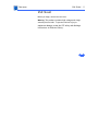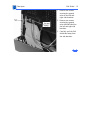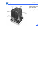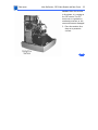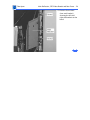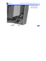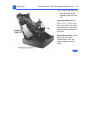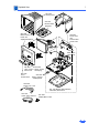
1
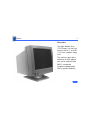
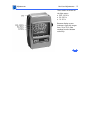
K Service Source
Apple Multiple Scan 1705
Display
K Service Source
Basics
Apple Multiple Scan 1705
Display
Basics
- 1
Overview
The Apple Multiple Scan
1705 Display is a low-cost
monitor with a 17-inch CRT
(15.8-inch viewable image
size).
This monitor comes with a
Macintosh-to-VGA adapter
so it can be used with most
IBM PC-compatible
computers equipped with
VGA or greater capability.
Basics
- 2
Features
Features of the 1705 monitor are
• A 17-inch color display
• Three different and independent lines to drive for red,
green, and blue.
• 111.5 MHz bandwidth
• High resolution CDT (Color Display Tube) display:
– Horizontal 1280 dots
– Vertical 1024 lines without blurring.
• Analog compatibility at an H-frequency of 30 to 65.8kHz.
This monitor is thoroughly checked and adjusted for an
optimum picture before it leaves the factory. However,
there may be some minor adjustments needed depending on
the particular location in which the monitor is operated.
Basics
- 3
Adjustments that can be made with the user controls are
• Brightness
• Contrast
• Horizontal center
• Width of picture
• Vertical center
• Picture height
• Picture curvature
• Picture side alignment
• Degauss
Factory settings can be restored by pressing the Down and
Up buttons at the same time.
Basics
- 4
Troubleshooting and Repair Tips
The monitor stand does not need to be removed before the
rear housing is removed.
When the video and main deflection boards are removed from
the bezel, special care must be taken to avoid damaging the
user brightness and contrast controls. These knobs protrude
about one inch past the main bracket and will not support the
weight of the main deflection board and attached brackets.
The video board and the main deflection board cannot be
separated without risk of damaging the CRT connector.
Therefore, the video board and main deflection board are
considered one module and will be replaced accordingly.
Connectors P302, P702, and P703 on the main deflection
board and video board are difficult to remove. Use a small,
flat-blade screwdriver to gently pry back the tabs before
removing these connectors.
Basics
- 5
Special Tools
When adjusting the monitor, check luminance readings
using a color analyzer or photometer. If such equipment is
not available, then use a 246 or an L-248 light meter. Do
not use other light meters. The readings given in the
Adjustments chapter are based on these meters.
The Apple high-voltage probe (Apple part number 0760392) will also be needed. Readings must be based on this
probe and not on other high-voltage probes available on the
market. Do not use other high-voltage probes.
The Display Service Utility (DSU) in the Diagnostics
Utilities folder on the Service Source Companion CD contains
display patterns to help adjust the display. Within the DSU,
select Pattern Selections: Multiple Scan 720/1705 to
access the screen patterns used for this monitor. Refer to
“Non User Adjustments” in the Adjustments chapter.
K Service Source
Specifications
Apple Multiple Scan 1705
Display
Specifications
Characteristics - 1
Characteristics
Picture Tube
Screen Resolution
Size/Active Video Display area 17 inches FST, 15.8-inch
diagonal viewable image size
Gun: In-line
Neck Diameter: 1.164 inches (29.1mm)
Phosphor: P22
Dot Pitch: 0.28 mm
720x400 at 70 Hz in VGA mode
640x480 at 60 Hz in VGA mode
1024x768 at 70 Hz in 1024x768 mode
640x480 at 70 Hz inVESA mode
800x600 at 72 Hz in SVGAII mode
1280x1024 at 84 Hz in 1280x1024 mode
1280x1024 at 60 Hz in UVA11 mode
Specifications
Scan Rates
Cable Connector
Input Signals
Characteristics - 2
Vertical refresh rate: 47-120 Hz
Horizontal scan rate: 31-65 kHz
In addition, to the above scan rates, this display works at the
following VESA (Video Electronics Standards Association)
standard modes. See the manual that came with the computer
or video card to determine which resolutions are supported:
640x480 at 60 Hz in VGA mode
640x480 at 75 Hz in VGA mode
800x600 at 60 Hz in SVGA mode
800x600 at 75 Hz in SVGA moce
15-pin miniature D-type
Red, green, blue signals; separate sync
Specifications
System Compatibility
Characteristics - 3
This display works with most IBM PC-compatible computers
equipped with VGA (Video Graphics Array) or greater
capability. A video card may need to be installed to use this
monitor with some computers. For more information, see
the computer manual.
Any computer equipped with a Boogie Board will support 24bit color.
1705/CPU Compatibility List
Standard
Configuration
With Additional
Memory
PowerMacintosh 9500
24-bit: 16.7 million
colors
24-bit: 16.7 million colors
Power Macintosh 8500
24-bit: 16.7 million
colors
24-bit: 16.7 million colors
Video Source
Specifications
Characteristics - 4
Video Source
Standard
Configuration
With Additional
Memory
Power Macintosh 7500
Power Macintosh 7200
24-bit: 16.7 million
colors
24-bit: 16.7 million colors
Power Macintosh 6200
16-bit: 32K colors
24-bit: 16.7 million colors
Powe Macintosh 8100
16-bit: 32K colors
24-bit: 16.7 million colors
Power Macintosh 7100
Power Macintosh 6100
8-bit: 256 colors
none
16-bit: 32K colors
no memory
upgrade
Power Macintosh with
AV
16-bit: 32K colors
no memory
upgrade
Quadra 610, 650, 700
800
4-bit: 16 colors
8-bit: 256 colors
Specifications
Characteristics - 5
Standard
Configuration
With Additional
Memory
Quardra 660AV,
Quadra
840Av, 900,950
8-bit: 256 colors
8-bit: 256 colors
no memory
upgrade
16-bit: 32 colors
Centris 610, 650
4-bit 16 colors
8-bit: 256 colors
Macintosh Display
Card 24AC
24-bit: 16.7 million
colors
24-bit: 16.7 million colors
Video Source
Specifications
Characteristics - 6
Video Source
Cards: 4•8,
8•24,8•24GC
Macintosh II, IIx IIcx,
IIfx
Macintosh IIci, IIsi
Macintosh LC 475,
Quadra 605
Macintosh LC, LCII,
LCIII
Macintosh PowerBooks
PowerBook duo Dock
Third Party Cards
Standard
Configuration
With Additional
Memory
This group of computers and cards are
not directly compatible with the 1705
Multiple Scan Display. They require a
Macintosh Display card 24AC, a third
party adapter, or third party software.
Specifications
Controls and Ports - 7
Controls and Ports
User Controls
I/O Ports
Power
Front panel: brightness and contrast control knobs; degauss
button; down and up buttons, which also perform the recall
function; and select buttons to reset factory settings and
adjust size, shape, alignment, and borders of picture
Power cord receptacle and video port
Specifications
Physical and Electrical - 8
Physical and Electrical
Power Supply
Size and Weight
Monitor Stand
Universal power supply
Voltage: AC 90-264 volts (V)
Frequency: 47/63 hertz (Hz), single phase
Power: 100 watts (W) maximum
Height: 17.6 in. (437 mm)
Width: 16.8 in. (420 mm)
Depth: 19.6 in. (479 mm)
Weight: 45 lb. (20.5 kg)
Built-in tilt and swivel
Specifications
Environmental - 9
Environmental
Temperature
Altitude
Humidity
Power Saving Feature
Operating: 50°F to 104°F (10°C to 40°C)
Shipping: -4°F to 151°F (-40°C to 65°C)
Storage: 32°F to 140°F (0°C to 60°C)
Operating: 0 ft. to 10,000 ft. (0 m to 3,000 m)
Shipping: 0 ft. to 35,000 ft. (0 m to 10,606 m)
Operating: 20% to 95% noncondensing
Shipping: 5% to 95% noncondensing
Storage: 5% to 95% noncondensing
This monitor conforms to the Energy Star program of the
United States Environmental Protection Agency. The power
saving feature is compatible with the Display Power
Management Standard (DPMS) of the Video Electronics
Standards Association (VESA).
K Service Source
Troubleshooting
Apple Multiple Scan 1705
Display
Troubleshooting
General/ - 1
General
In this chapter, you will find Symptom Charts designed to help you
diagnose and repair the Multiple Scan 1705 Display.
Go through the Symptom Charts until you find the right symptom.
Because cures are listed in the order of the most likely solution,
begin with the first listed cure. Verify whether or not the product
continues to exhibit the symptom. If the symptom persists, try
the next cure.
If you require additional assistance, contact Apple Technical
Support.
Troubleshooting
First Checklist/ - 2
First Checklist
Important: Many Apple Multiple Scan Display modules returned
for repair are found to be fully operational. Read this checklist
before you return a module, and prevent needless module
replacement and unnecessary time delays.
The Apple Multiple Scan 1705 Display is not
compatible with all computers.
This display works with most IBM PC-compatible computers
equipped with VGA (Video Graphics Array) or greater capability. A
video card may need to be installed to use this display with some
computers. For more information, see the computer manual.
The display is preadjusted to work with any computer that has the
following timing ranges:
• Horizontal scan rate of 31-65 kilohertz
Troubleshooting
First Checklist/ - 3
• Vertical refresh rate of 47-120 hertz
For more information on what computers or video cards are
compatible with the 1705 display, see the Specifications chapter.
The CRT raster will not always resemble a perfect
rectangle.
CRT tolerances allow for some distortion. Additional distortion can
be caused by magnetized metal objects (desks, file cabinets, etc.).
Move the unit to a different location if you notice raster bowing or
bent raster edges.
Jitter, faint lines, or screen movement can be caused
by external interference such as electronic devices
and fluorescent lights.
Move the unit to another room or building to help determine if
external interference is the source of the problem.
Troubleshooting
First Checklist/ - 4
A maladjusted screen can mimic the symptoms of
deflection board or CRT failures.
By performing the adjustment procedures, you might determine if
one or more of the adjustments is the cause of the problem.
CRTs rarely fail.
Needless CRT replacement can be prevented by checking display
adjustments, checking the possibility of other defective modules,
and accepting small imperfections in screen display.
If you have any doubts about whether a CRT is defective, contact
Apple Technical Support.
Troubleshooting
Symptom Charts/No Raster - 5
Symptom Charts
No Raster
No raster with LED on
1
2
3
4
5
6
Check monitor cable connections. Thumbscrews must be
tightened securely. If a video card is used, the monitor
cable must be secured to the card.
Adjust brightness and contrast controls (see “User
Adjustments” in Adjustments).
A screen saver may be activated. Move mouse or press any
key to reactivate the screen.
The Energy Saver option may be on. Move mouse or press
any key on the keyboard to reactivate the display. The
display reactivates in about 20 seconds.
Some Macintosh computers may not wake up after Energy
Saver is activated. Restart computer and disable Energy
Saver.
Go to “Check High Voltage.”
Troubleshooting
Symptom Charts/No Raster (Continued) - 6
No Raster (Continued)
No raster with LED off
1
2
3
4
5
6
Ensure that power cord is plugged in properly.
Check power outlet at the wall by plugging in an
electronic device that works.
If the display is plugged into a computer, ensure that
computer is on and power cord firmly connected.
Check video cable connections at computer and monitor.
Thumbscrews must be secure. If a video card is used, the
video cable must be properly connected to it.
Replace video and main deflection boards. See “Main
Deflection, CRT/Video Boards and Rear Fence” in Take
Apart. Adjust cutoff and white balance. See “Cutoff and
White Balance” in Adjustments.
Send the monitor to Apple for repair.
Troubleshooting
Symptom Charts/No Raster (Continued) - 7
No Raster (Continued)
No raster with LED
yellow
1
2
Check video cable connections at computer and monitor.
Thumbscrews must be secure. If a video card is used, the
video cable must be properly connected to it.
See “Do You Need a Video Card” in monitor user manual.
Troubleshooting
Symptom Charts/Video - 8
Video
Screen flickers
1
2
3
4
5
6
Check the monitor cable connections. The thumbscrews
must be tightened securely. If a video card is used, the
monitor cable must be secured to the card.
Check for external interference by moving the monitor to
another location.
If using more than one monitor with a computer, move the
monitors so they are least 18 inches apart.
If a video card is used, check the refresh rate. Refresh
rates below 60 Hz may cause flicker. See the video card
manual to raise the refresh rate above 60 Hz.
Doublecheck items 1 through 4.
Replace the video and main deflection boards. See “Main
Deflection, CRT/Video Boards and Rear Fence” in Take
Apart. Adjust cutoff and white balance. See “Cutoff and
White Balance” in Adjustments.
Troubleshooting
Symptom Charts/Video (Continued) - 9
Video (Continued)
Screen is blurred
1
2
3
Raster is too bright
1
2
3
4
Adjust Focus at VR F1 and F2. See “Focus Adjustment” in
Adjustments.
Doublecheck focus.
Replace the video and main deflection boards. See “Main
Deflection, CRT/Video Boards and Rear Fence” in Take
Apart. Adjust cutoff and white balance. See “Cutoff and
White Balance” in Adjustments.
Adjust brightness control. See “User Adjustments” in
Adjustments.
Adjust cutoff and white balance. See Adjustments.
Doublecheck items 1 and 2.
Replace video and main deflection boards. See “Main
Deflection, CRT/Video Boards and Rear Fence” in Take
Apart. Adjust cutoff and white balance. See “Cutoff and
White Balance” in Adjustments.
Troubleshooting
Symptom Charts/Video (Continued) - 10
Video (Continued)
Colors are too green,
red, or blue, and the
screen is unreadable
1
2
3
4
5
No color
Ensure that the video card or computer video port is good by
connecting a monitor that is known to be good.
Ensure that the video cable is properly connected and the
thumbscrews are secure. If a video card is used, the video
cable must be properly attached to it.
Adjust cutoff and white balance. See “Cutoff and White
Balance” in Adjustments.
Doublecheck items 1 and 2.
Replace the video and main deflection boards. See “Main
Deflection, CRT/Video Boards and Rear Fence” in Take Apart.
Adjust cutoff and white balance. See “Cutoff and White
Balance” in Adjustments.
Ensure that the setting for the number of colors in the Monitor
Control panel is correct and not set to black & white. See the
monitor user manual.
Troubleshooting
Symptom Charts/Geometry - 11
Geometry
Raster is too short, tall,
narrow, or wide
1
2
3
Adjust the width and height of the screen. See “User
Adjustments” in Adjustments.
Doublecheck the user controls.
Replace video and main deflection boards. See “Main
Deflection, CRT/Video Boards and Rear Fence” in Take
Apart. Adjust cutoff and white balance. See “Cutoff and
White Balance” in Adjustments.
Troubleshooting
Symptom Charts/Geometry (Continued) - 12
Geometry (Continued)
Raster is not centered
1
2
3
4
5
Check that the distortion is not due to environmental
conditions. Move the monitor.
Adjust the vertical and horizontal center of screen. See
“User Adjustments” in Adjustments.
Adjust the raster center at VR701. See “Raster Center
Adjustment” in Adjustments.
Doublecheck items 1 through 3.
Replace video and main deflection boards. See “Main
Deflection, CRT/Video Boards and Rear Fence” in Take Apart.
Adjust cutoff and white balance. See “Cutoff and White
Balance” in Adjustments.
Troubleshooting
Symptom Charts/Miscellaneous - 13
Miscellaneous
Indicator light goes
out before
adjustment of display
controls is completed
The LED will go out after 10 seconds by design. This is a normal
function.
Troubleshooting
Checking High Voltage - 14
Checking High Voltage
±Warning: Read all of the warnings, notes, and steps of this
procedure before beginning.
Voltage at the anode, with the power on, can cause
serious injury. Doublecheck all multimeter connections before
taking the reading.
±Warning:
Probe the anode carefully. Serious damage and
injury may occur if the anode is knocked off while the CRT is
charged.
±Warning:
Note: Do not attempt this procedure without the Apple highvoltage probe. Use only the Apple high-voltage probe. Other highvoltage probes will not give accurate readings for this procedure.
Troubleshooting
Checking High Voltage - 15
Before you begin, remove:
• Rear Housing
• EMI Shield
1
Attach the Apple high-voltage probe to the multimeter and
attach the ground wire to the chassis.
2 Be sure the monitor is attached to a computer and has power.
3 Turn on the monitor.
4 Carefully insert the probe under the anode wire connector.
5 The reading should be 25 VDC on the meter. This is actually
25 kV. Most of the voltage is across the high-voltage probe.
Warning: Do not remove the probe from under the anode wire
connector until power is turned off. Injury or damage to equipment may
occur.
6
7
8
9
Turn off monitor.
Unplug monitor.
Remove the probe from under the anode wire connector.
Go to the “No Raster Flowchart.”
Troubleshooting
Checking High Voltage - 16
Note: Refer to these pictures when using the “No Raster
Flowchart.”
A
B
C
A
Troubleshooting
No Raster Flowchart - 17
No Raster Flowchart
No Raster Flowchart
Check HighVoltage
Did
multimeter
read 25.0 VDC
(25 kv ?)
no
yes
1. Set multi-meter to DC.
2. Attach ground probe
(black) to monitor frame
3. Touch multimeter red probe to CRT
socket pin H. See picture A.
Does
multimeter
read about
6 VDC?
no
1. Replace Main Deflection,
CRT/Video, Rear Fence.
See Take Apart chapter.
2.Adjust cutoff and white
balance. See Adjustments
Chapter.
END
Go to:
A
yes
Check the computer
and video card.
Are the
computer
and video card
okay?
no
Fix computer or video card.
yes
Go to:
B
END
Troubleshooting
No Raster Flowchart (Continued) - 18
No Raster Flowchart (Continued)
A
Measure voltage at pin 8
(labeled 6.3V).
See Picture A.
Does
multimeter
read about
6 VDC?
yes
1. Replace Main Deflection,
CRT/Video, Rear Fence.
See Take Apart chapter.
2.Adjust cutoff and white
balance. See Adjustments
Chapter.
no
Check interconnect cable and
connectors P-702, P-703 and
B.
P-302. See Picture C.
Are
cable
and connectors
okay?
no
yes
Replace video
interconnect cable.
See Take Apart Chapter.
END
END
Troubleshooting
No Raster Flowchart (Continued) - 19
No Raster Flowchart (Continued)
B
Slowly turn screen the control on the
flyback transformer, clockwise.
See picture C.
Does
raster
become
visible
?
no
yes
1. Replace Main Deflection,
CRT/Video, Rear Fence.
See Take Apart chapter.
2.Adjust cutoff and white
balance. See Adjustments
Chapter.
Adjust cutoff and white balance.
See A djustments Chapter.
Was
outcome
successful
?
no
yes
END
END
K Service Source
Take Apart
Apple Multiple Scan 1705
Display
Take Apart
Special Safety Precautions - 1
Special Safety Precautions
The only potential source of X-Radiation is the CRT. When
the high voltage circuitry is operating properly, there is no
possibility of an X-Radiation problem. Keep the high voltage
at the factory-recommended level of 26 kV. This voltage
must not exceed 29 kV at zero beam current at rated voltage.
See Adjustments chapter for checking and adjusting high
voltage.
Helpful drawing
At the end of this chapter, there is a simplifed wiring
diagram that shows all of the connector locations and names.
You may want to print it out.
Take Apart
Monitor Stand - 2
Monitor Stand
No first steps required.
1
Remove the video and
power cables from the
back of the monitor.
Caution: When the monitor
is face down, it is resting on
the CRT screen. The CRT
must rest on a protective,
nonabrasive surface or the
screen will become damaged.
Take Apart
Monitor Stand - 3
2
Place the monitor face
down on a protective
mat.
Take Apart
Monitor Stand - 4
3
Depress the tab on the
rear of the housing, just
behind the monitor
stand.
Take Apart
Monitor Stand - 5
4
Slide the monitor stand
toward the back of the
monitor and remove.
Take Apart
Control Panel Cover - 6
Control Panel
Cover
No first steps required.
Caution: Grasp the cover as
close to the hinge as
possible, or the cover may
break.
1
2
3
Open the control panel
cover.
Grasp the cover at one
side and pull so slot
disengages bezel.
Repeat this procedure
for the other side of the
panel.
Take Apart
Rear Housing - 7
Rear Housing
First:
No first steps required
Warning: This product contains high voltage and a highvacuum picture tube. To prevent serious injury or
equipment damage, review the CRT safety and discharge
instructions in Bulletins/Safety.
Take Apart
Rear Housing - 8
1
Remove the power and
video cables from the
monitor.
Caution: When the monitor
is face down, it is resting on
the CRT screen. The CRT
must rest on a protective,
nonabrasive surface or the
screen will become damaged.
Take Apart
Rear Housing - 9
2
Place the monitor face
down on a protective
mat.
Take Apart
Rear Housing - 10
3
4
Remove four screws
securing the rear
housing to the bezel.
Lift the rear housing
from the chassis.
Take Apart
EMI Shield - 11
EMI Shield
Before you begin, remove the rear cover.
Warning: This product contains high voltage and a highvacuum picture tube. To prevent serious injury or
equipment damage, review the CRT safety and discharge
instructions in Bulletins/Safety.
Take Apart
EMI Shield - 12
1
2
3
Remove two screws
securing the ground
wires to the left and
right side brackets.
Remove two screws
securing the ground
wires and EMI shield to
the left and right side
brackets.
Carefully pull the EMI
shield tabs away from
the side brackets.
Take Apart
EMI Shield - 13
4
5
Remove two screws
securing the EMI shield
to the main bracket.
Remove two screws
securing the EMI shield
to the rear fence.
Take Apart
EMI Shield - 14
6
Tilt the EMI shield so the
shield tabs clear the
slots in the rear fence
and lift off.
Replacement Note: If you
need to remove the grounding
brackets, remove one at a
time, so the other grounding
bracket can be referenced
for proper installation of
the tabs into the EMI shield.
Replacement Caution: The
grounding bracket tabs
must be inserted correctly
or the CRT will not be
properly grounded,
resulting in equipment
damage.
Take Apart
Main Deflection, CRT/Video Boards and Rear Fence - 15
Main Deflection, CRT/Video Boards
and Rear Fence
Before you begin:
• Remove Rear Housing
• Remove EMI Shield
• Discharge CRT
Warning: This product contains high voltage and a highvacuum picture tube. To prevent serious injury or
equipment damage, review the CRT safety and discharge
instructions in Bulletins/Safety.
Caution: To prevent ESD damage to the components, wear a
grounding wriststrap. Never use a grounding wriststrap
until after discharging the CRT.
Take Apart
Main Deflection, CRT/Video Boards and Rear Fence - 16
1
Set the monitor on the
bottom bracket.
Take Apart
Main Deflection, CRT/Video Boards and Rear Fence - 17
2
Disconnect two ground
wires from the video
board.
Take Apart
Main Deflection, CRT/Video Boards and Rear Fence - 18
3
4
Disconnect the twowire cable from P303
on the video board.
Disconnect the ground
wire from the bottom of
the video board
Take Apart
Main Deflection, CRT/Video Boards and Rear Fence - 19
5
Remove one screw
securing the ground wire
to the rear fence.
Take Apart
Main Deflection, CRT/Video Boards and Rear Fence - 20
Caution: Damage will occur
if the CRT is marred with
pliers when removing the
hot glue.
Note: If there is a portion of
hot glue hanging from the
connector, use it to peel the
hot glue from the CRT.
6
Using needle-nose
pliers, peel the hot glue
from the CRT.
Take Apart
Main Deflection, CRT/Video Boards and Rear Fence - 21
Caution: CRT pins are easily
damaged. Gently rock the
video board back and forth
while pulling it away from
the CRT.
Note: If gently rocking and
pulling the video board does
not loosen it from the CRT,
remove more hot glue.
7
Remove the video board
from the CRT.
Take Apart
Main Deflection, CRT/Video Boards and Rear Fence - 22
Warning: Be sure the
monitor has no power and
the CRT has been properly
discharged. Serious injury
could occur if the anode wire
is removed while the CRT is
charged.
8
Remove the anode wire
connector from the CRT.
Take Apart
Main Deflection, CRT/Video Boards and Rear Fence - 23
Caution: When the monitor
is face down, it is resting on
the CRT screen. The CRT
must rest on a protective,
nonabrasive surface or the
screen will become damaged.
9
Place the monitor face
down on a protective
surface.
Take Apart
Main Deflection, CRT/Video Boards and Rear Fence - 24
10 Remove four screws
(two each bracket)
securing the left and
right side brackets to the
bezel.
Take Apart
Main Deflection, CRT/Video Boards and Rear Fence - 25
11 Remove two screws
securing the main
bracket to the bezel.
Take Apart
Main Deflection, CRT/Video Boards and Rear Fence - 26
12 Lift and tilt the video and
main deflection board
assembly away from the
CRT.
Replacement Note: Ensure
P601, P701, P702, P703,
P901 and P902 have cables
installed before securing the
side and bottom brackets to
the bezel.
Replacement Caution: Do not
pinch any wires when
positioning the side and
bottom brackets into the
bezel.
Take Apart
Main Deflection, CRT/Video Boards and Rear Fence - 27
13 Disconnect the twowire cable from P701
on the main deflection
board.
14 Disconnect the twowire cable from P601
on the main deflection
board.
Take Apart
Main Deflection, CRT/Video Boards and Rear Fence - 28
15 Disconnect the twowire cable from P902
on the main deflection
board and remove both
cables from the nylon
support.
Take Apart
Main Deflection, CRT/Video Boards and Rear Fence - 29
Caution: Ground cables are
supporting the weight of the
video and main deflection
board assembly. Support
this assembly with your
hand when removing the
ground cables.
16 Remove the screws
securing the two ground
cables to the bottom
bracket and remove the
video and main deflection
board assembly from
the CRT and bezel.
Take Apart
Main Deflection, CRT/Video Boards and Rear Fence - 30
17 Remove the user
brightness and contrast
knobs from the controls
on the main deflection
board.
Take Apart
Main Deflection, CRT/Video Boards and Rear Fence - 31
18 Remove the screw
securing the right side
bracket to the bottom
bracket.
19 Slide the bracket up to
clear the main bracket
support and remove.
20 Remove the screw
securing the left side
bracket to the bottom
bracket.
21 Slide the bracket up to
clear the main bracket
support and remove.
Take Apart
Bezel - 32
Bezel
Before you begin, remove the following:
• Rear Housing
• EMI Shield
Warning: This product contains high voltage and a highvacuum picture tube. To prevent serious injury or
equipment damage, review the CRT safety and discharge
instructions in Bulletins/Safety.
Take Apart
Bezel - 33
1
2
3
Place a sturdy, nonabrasive object (such as
a large book about 3” x
11” x 8”) next to the
monitor.
Lift the monitor from
the protective surface
and set it on the object.
Position the monitor so
the CRT and the lower
edge of the bezel are
supported by the object.
Take Apart
Bezel - 34
4
Remove two screws
securing the ground
straps to the bottom
bracket.
Take Apart
Bezel - 35
5
6
Remove four screws
securing the left and
right side brackets (two
screws each) to the
bezel.
Remove the two screws
securing the main
bracket to the bezel.
Take Apart
Bezel - 36
7
Remove the four screws
securing the D-coil
holders and CRT to the
bezel.
Replacement Note: Be sure
to install the D-coil holders
when installing the screws.
Take Apart
Bezel - 37
8
Gently slide the monitor
so the bezel is no longer
supported by the object
and let the bezel rest on
the protective surface.
Caution: The CRT and
deflection board are
connected only by cables.
Support both when lifting or
connectors may be damaged.
Caution: User brightness
and contrast controls will
not support the weight of the
video and deflection board
assembly. Set the assembly
on supports or the controls
may be damaged.
Take Apart
Bezel - 38
9
Position two supports
(1.5 to 2 inches tall) on
the protective surface
about one foot apart.
10 Carefully lift the CRT
and video and main
deflection board
assembly from the bezel.
11 Set the CRT on the
protective surface and
the video and main
deflection board
assembly on the
supports.
Take Apart
Bezel - 39
Replacement Note: Carefully line up the brightness and
contrast controls into the bezel when installing. The controls
will bind on the bezel tabs and not operate if not carefully
aligned.
Replacement Note: Position a sturdy nonabrasive object
inside the bezel. Carefully place the CRT and video and main
deflection board assembly on the sturdy object. Lift the bezel
and line up the screw holes and brightness and contrast
knobs with the CRT and video and deflection board assembly.
Slide the monitor until the lower edge of the bezel is
supported by the object. This will hold the bezel in place
while the screws are installed.
Take Apart
Brightness and Contrast Knobs - 40
Brightness and Contrast Knobs
Warning: This product contains high voltage and a highvacuum picture tube. To prevent serious injury or
equipment damage, review the CRT safety and discharge
instructions in Bulletins/Safety.
Before you begin, remove the following:
• Rear Housing.
• EMI Shield
• Bezel
Slide the brightness and contrast knobs from their controls.
Take Apart
On/Off Switch with Spring - 41
On/Off Switch with Spring
Warning: This product contains high voltage and a highvacuum picture tube. To prevent serious injury or
equipment damage, review the CRT safety and discharge
instructions in Bulletins/Safety.
Before you begin, remove the following:
• Rear Housing.
• EMI Shield
• Bezel
Take Apart
On/Off Switch with Spring - 42
1
Note: The switch is
spring loaded and will
fly when pushed from
the bezel.
Pinch two retainers on
the on/off switch
together and push from
the back of the bezel.
Take Apart
Control Panel Cover Latch - 43
Control Panel
Cover Latch
Before you begin, remove the
following
• Rear Housing.
• EMI Shield
• Bezel
1
2
Prop the bottom edge of
the bezel up about two
inches.
Open the control panel
cover.
Take Apart
Control Panel Cover Latch - 44
3
With an object about
one-half inch in
diameter and three
inches long, drive the
latch from the inside of
the bezel.
Replacement Note: The
latch can be installed when
the monitor is fully
assembled
Take Apart
Rear Fence, Internal Video, AC Inlet Assembly - 45
Rear Fence, Internal Video, AC Inlet
Assembly
Before you begin, remove the following:
• Rear Housing
• EMI Shield
Warning: This product contains high voltage and a highvacuum picture tube. To prevent serious injury or
equipment damage, review the CRT safety and discharge
instructions in Bulletins/Safety.
Take Apart
Rear Fence, Internal Video, AC Inlet Assembly - 46
1
Remove all wires from
the nylon support on the
right side bracket.
Take Apart
Rear Fence, Internal Video, AC Inlet Assembly - 47
Note: Steps 2 through 7 are
for accessing P901 only.
2
3
4
Remove two screws
securing the right side
bracket to the bezel.
Remove one screw
securing the right side of
the main bracket to the
bezel.
Remove one screw
securing the right side
bracket to the bottom
bracket.
Take Apart
Rear Fence, Internal Video, AC Inlet Assembly - 48
5
Gently lift the right side
of the bottom bracket so
the side bracket just
clears the bezel support
structures.
Take Apart
Rear Fence, Internal Video, AC Inlet Assembly - 49
6
Slide the side bracket
from the main bracket
support and remove.
Take Apart
Rear Fence, Internal Video, AC Inlet Assembly - 50
7
8
Support the main
deflection board with
your hand.
Disconnect the twowire cable from P901
on the main deflection
board.
Take Apart
Rear Fence, Internal Video, AC Inlet Assembly - 51
9
Remove the screw
securing P704 cable to
the rear fence.
Take Apart
Rear Fence, Internal Video, AC Inlet Assembly - 52
10 Remove the screw
securing the video board
ground wire to the fence
Take Apart
Rear Fence, Internal Video, AC Inlet Assembly - 53
11 Carefully straighten the
tabs on the cover shield
plate.
12 Remove the cover shield
plate from the video
board.
Replacement Note: Do not
bend the cover shield plate
tabs more than necessary.
They are easily broken.
Take Apart
Rear Fence, Internal Video, AC Inlet Assembly - 54
13 Disconnect the twelvewire cable from P301
on the video board.
• Insert a small flatblade screwdriver
between the connector
and tab.
• Gently move the tab
away from the
connector and work
one side of the
connector up until it
clears the tab.
Take Apart
Rear Fence, Internal Video, AC Inlet Assembly - 55
• Repeat this procedure
for the other side of
the connector and
remove.
14 Remove two screws
securing the rear fence
to the top of the main
bracket.
Take Apart
Rear Fence, Internal Video, AC Inlet Assembly - 56
15 Remove two screws
securing the fence to the
back of the main and
bottom brackets.
16 Slide the rear fence up
and remove it from the
main and bottom
brackets.
Take Apart
Video Interconnect Cable - 57
Video Interconnect Cable
Before you begin, remove the following:
• Rear Housing
• EMI Shield
Warning: This product contains high voltage and a highvacuum picture tube. To prevent serious injury or
equipment damage, review the CRT safety and discharge
instructions in Bulletins/Safety.
Caution: To prevent ESD damage to components, wear a
grounding wriststrap. Never use a grounding wriststrap
until after discharging the CRT.
Take Apart
Video Interconnect Cable - 58
1
Remove two ground
wires from the top of the
video board.
Take Apart
Video Interconnect Cable - 59
Warning: Be sure the
monitor has no power and
the CRT has been properly
discharged. Serious injury
could occur if the anode wire
is removed while the CRT is
charged.
2
Remove the anode wire
connector from the CRT.
Take Apart
Video Interconnect Cable - 60
3
Remove four screws
(two each bracket)
securing the left and
right side brackets to the
bezel.
Take Apart
Video Interconnect Cable - 61
4
Remove two screws
securing the main
bracket to the bezel.
Take Apart
Video Interconnect Cable - 62
Caution: Care must be taken
not to disturb the user
brightness and contrast
control knobs while lifting
the video and main deflection
board assembly.
5
Lift and tilt the video and
main deflection board
assembly away from the
CRT.
Take Apart
Video Interconnect Cable - 63
6
Remove the cable from
the nylon support.
Note: Connector on P703 is
hot-glued.
7
Disconnect the cable
from P702 and P703 on
the main deflection board
to remove the cable from
both connectors:
Take Apart
Video Interconnect Cable - 64
• Insert a small flat
blade screw-driver
between the connector
and the tab.
• Gently move the tab
away from the
connector and work
one side of the
connector up until it
clears the tab.
• Repeat this procedure
for the other side of
the connector.
Take Apart
Video Interconnect Cable - 65
8
9
Carefully straighten the
tabs on the cover shield
plate.
Remove the cover shield
plate from the video
board.
Replacement Note: Do not
bend the cover shield plate
tabs more than necessary.
They are easily broken.
Take Apart
Video Interconnect Cable - 66
10 Disconnect the 12-wire
cable from P302 on the
video board.
• Insert a small flatblade screwdriver
between the connector
and tab.
• Gently move the tab
away from the
connector and work
one side of the
connector up until it
clears the tab.
Take Apart
Video Interconnect Cable - 67
• Repeat this procedure
for the other side of
the connector.
11 Remove the cable from
the monitor.
Take Apart
- 68
Multiple Scan 1705 Display Simplified Wiring Diagram
P703
P901
P902
P601
P701
P702
P704
AC Socket
FBT
P302
P304
P301
K Service Source
Additional Procedures
Apple Multiple Scan 1705
Display
Additional Procedures
Introduction - 1
Introduction
The “Adjusting the Degaussing Coils” procedure describes
the proper position of the degaussing coils in relation to the
CRT corners and the canceling coil.
Follow this procedure whenever you take apart or
reassemble a unit.
Important: To maximize performance of the Apple Multiple
Scan 1705 Display, the degaussing coils must
• Remain securely attached to the corners of the CRT
• Remain at least 1.25 inches (30 mm) from the bottom
canceling coil on the yoke of the CRT
Additional Procedures
Adjusting the Degaussing Coils - 2
Adjusting the
Degaussing Coils
Before you begin, refer to
the Take Apart chapter to
remove
• Monitor stand
• Rear housing
• EMI shield
Additional Procedures
Adjusting the Degaussing Coils - 3
1
2
At the top two corners of
the CRT, release the
degaussing coil from the
two bendable tabs.
Lower the degaussing
coil so its top corners
are positioned at least 2
inches (50 mm) away
from the CRT corner
screws. Bend the tabs to
secure the degaussing
coil in this position.
Additional Procedures
Adjusting the Degaussing Coils - 4
3
Tape
4
Note: Do not remove the
board assemblies. The
illustration at left shows
the boards removed for
clarification only.
Check for tape or clips
where the degaussing
coils overlap (near the
deflection yoke).
If the degaussing coils
are not attached with
tape or clips, use two
pieces of electrical tape
(about 6 inches long,
each) to fasten the two
coils closely together.
Additional Procedures
Adjusting the Degaussing Coils - 5
5
At the bottom two
corners of the CRT,
release the degaussing
coil from the two
bendable tabs.
Additional Procedures
Adjusting the Degaussing Coils - 6
6
Pull the degaussing coil
downward until the
overlapped taped section
(where the degaussing
coils meet) is positioned
1.25 inches (30 mm)
from the bottom
canceling coil.
Canceling
Coil
Degaussing
Coil
Note: Do not remove the
board assemblies.
Tab
Tab
7
Bend the two bottom
tabs to secure the
degaussing coil in this
position.
Reassemble the monitor.
K Service Source
Adjustments
Apple Multiple Scan 1705
Display
Adjustments
User Adjustments - 1
User Adjustments
The image adjusted by the user is saved into the memory on
the monitor CPU (Central Processing Unit). Therefore,
when the monitor is powered on again, the image is displayed
exactly the same as saved by the user.
Adjustments
User Adjustments - 2
Controls
Power Button
Power LED
A flip-down door covers the
controls on the front of the
monitor. Gently push on the
top center of the door to open
or close it.
The power button is located
to the right of the control
panel and power LED.
Control Panel
Flip-Down Door
Adjustments
User Adjustments - 3
Brightness
Rotate the brightness
control clockwise or
counterclockwise to
increase or decrease
brightness.
Contrast
Rotate the contrast control
clockwise or
counterclockwise to
increase or decrease
contrast.
Adjustments
User Adjustments - 4
Geometry
Horizontal Center
1
2
Press and hold the
SELECT button until the
indicator light for the
horizontal center icon
goes on.
Press the DOWN and UP
buttons to move the
center of the picture
left or right.
Adjustments
User Adjustments - 5
Width of Picture
1
2
Press and hold the
SELECT button until the
indicator light for the
width icon goes on.
Press the DOWN and UP
buttons to narrow or
widen the picture.
Adjustments
User Adjustments - 6
Vertical Center
1
2
Press and hold the
SELECT button until the
indicator light for the
vertical center icon goes
on.
Press the DOWN and UP
buttons to move the
center of the picture
down or up.
Adjustments
User Adjustments - 7
Height of Picture
1
2
Press the SELECT button
until the indicator light
for the height icon goes
on.
Press the DOWN and UP
buttons to decrease or
increase the height of the
picture.
Adjustments
User Adjustments - 8
Picture Curvature
1
2
Press and hold the
SELECT button until the
indicator light for the
picture curvature icon
goes on.
Press the DOWN and UP
buttons to change the
arch of the picture
border.
Adjustments
User Adjustments - 9
Picture Side Alignment
1
2
Press and hold the
SELECT button until the
indicator light for the
side alignment icon goes
on.
Press the DOWN and UP
buttons to change the
alignment.
Adjustments
User Adjustments - 10
Degauss
Press the DEGAUSS button to
degauss the monitor.
Adjustments
User Adjustments - 11
Factory Settings
Note: Picture controls are
generally fine-tuned by the
user.
To revert to the factory
settings, press the DOWN
and UP buttons at the same
time.
Adjustments
Non User Adjustments - 12
Non User Adjustments
Warning: This product contains high voltage and a highvacuum picture tube. To prevent serious injury or
equipment damage, review the CRT safety and discharge
instructions in Safety Information under the DO menu.
Warning: Use a plastic screwdriver to make all adjustments
to the controls located on the video and main deflection
boards.
Caution: To prevent ESD damage to components, wear a
grounding wriststrap. Never use a grounding wriststrap
until after discharging the CRT.
Important: At the end of this chapter, there is a drawing
locating all of the adjustment points. You may want to print
it out.
Adjustments
Non User Adjustments - 13
Light Meter Setup
Note: When a color analyzer
or photometer are not
available, use an R77, a
246, or an L-248 light
meter to measure the
brightness of the monitor
screen.
Model R77 (Apple part
number 076-0310) is the
newest light meter model
available.
Adjustments
Non User Adjustments - 14
Model R77
The R77 light meter is
capable of reading luminance
from 10 to 1,000
footcandles (fc).
Before you begin, remove
the 10X multiplier plate
from the lens.
Adjustments
Non User Adjustments - 15
Three scales are shown on
the light meter:
• 200-1000 fc
• 50-250 fc
• 10-50 fc
Because display screen
luminance typically ranges
from 10 to 50 fc, take
readings from the bottom
scale only.
Adjustments
Non User Adjustments - 16
To measure a display
screen’s luminance,
1
2
Set the scale switch to
the bottom position (to
set up the 10-50 fc
scale).
Place the lens against the
middle of the screen and
read the bottom scale.
Note: When the light meter
is not in use, slide the scale
switch to its top position,
and store the meter in its
protective case.
Important: If you suspect the
light meter is giving false
Adjustments
Non User Adjustments - 17
readings, verify the
readings with a known-good
light meter or photometer.
Also check the age of the R77
light meter by its four-digit
manufacturing date stamp
(such as 0398 for March
1998).
Caution: Dropping the
meter can permanently
damage its accuracy. A
shock-damaged meter might
read incorrectly or its
pointer may not drop to
zero.
Adjustments
Non User Adjustments - 18
Model 246
Note: Follow this procedure
to set up the meter when
making brightness
adjustments.
1
Remove the metal slide,
if installed, and insert
it into the slot on the
back of the meter.
Adjustments
Non User Adjustments - 19
Note: The white disk lens is
removed only for some
procedures.
2
Remove the white disk
lens. Turn it
counterclockwise so the
dot on the lens aligns
with the dot on the meter
and, pull the lens from
the meter.
Adjustments
Non User Adjustments - 20
3
Rotate the lens head of
the meter to face the
monitor.
Adjustments
Non User Adjustments - 21
4
Hold the lens against the
middle of the monitor
screen.
Adjustments
Non User Adjustments - 22
Model L-248
Note: Follow this procedure
to set up the meter when
making brightness
adjustments.
1
Press the red button on
the back of the meter to
check the battery. If the
reading is out of the red
area on the scale,
replace the battery.
Adjustments
Non User Adjustments - 23
2
Slide the scale selector
to the lower position to
access the 2 to 10 scale.
Adjustments
Non User Adjustments - 24
3
Slide the selector to the
upper position to access
the 10 to 18 scale.
Adjustments
Non User Adjustments - 25
4
Slide the diffuser away
from the lens when using
the meter to read
brightness.
Adjustments
Non User Adjustments - 26
5
6
Hold the lens against the
middle of the monitor
screen.
Press the button on the
right to take the
reading. The needle will
lock in place when the
button is released.
Adjustments
Non User Adjustments - 27
Raster Center
Adjustment
Before you begin, remove the
following:
• Rear Housing
• EMI Shield
1
2
Using Display Service
Utility on the Service
Source Companion CD,
select the display
pattern containing a
grid on a white field.
Set the user controls to
maximum brightness
and contrast (clockwise).
Adjustments
Non User Adjustments - 28
3
Adjust VR701 (HRASTER CENTER) so the
picture is horizontally
centered on the screen.
Adjustments
Non User Adjustments - 29
Focus Adjustment
Before you begin, remove the
following:
• Rear Housing
• EMI Shield
1
2
Using Display Service
Utility, select the
display pattern
containing nine gray
boxes on a dark field.
Set the user controls to
maximum brightness
and contrast (clockwise).
Adjustments
Non User Adjustments - 30
3
Adjust the focus at VR F1
and F2 on the flyback
transformer, until the
focus test pattern
reaches the best possible
focus at the center of the
screen.
Adjustments
Non User Adjustments - 31
High-Voltage
Adjustment
Note: Adjust the high voltage
whenever a module is
replaced or if the setting at
VR501 was accidentally
changed.
Before you begin, remove
the following:
• Rear Housing
• EMI Shield
Adjustments
Non User Adjustments - 32
1
9 in. (225mm)
12 in. (300mm)
2
Using Display Service
Utility, select the
display pattern
containing a grid on a
white field.
Using the height and
width controls on the
front control panel and a
plastic ruler, adjust the
screen size to 12 inches
(300 mm) by 9 inches.
(225 mm).
Adjustments
Non User Adjustments - 33
3
4
Attach the multimeter.
• Attach the negative
probe to the chassis
(ground).
• Hold the positive
probe to the lead on
the striped side of the
D709 cathode.
Adjust the voltage at
VR501(HV) until the
multimeter reads 29. 5
volts ± 0. 1volt.
Adjustments
Non User Adjustments - 34
Cutoff and White
Balance Adjustments
Before you begin,
• Run the monitor for a
minimum of 15 minutes.
• Degauss CRT Screen
• Remove Rear Housing
• Remove EMI Shield
• Adjust High Voltage
Note: Cutoff and white
balance adjustments must be
performed whenever the
video and main deflection
boards are replaced.
Replacement modules need to
be adjusted to the monitor’s
Adjustments
Non User Adjustments - 35
CRT before color and
brightness can be
reproduced correctly.
Adjustments
Non User Adjustments - 36
Presets for Cutoff and
White Balance
Adjustments
1
Set the user controls to
maximum brightness
and contrast (clockwise).
Adjustments
Non User Adjustments - 37
2
Adjust VR305 (SUB
BRIGHT) to its maximum
position (clockwise).
Adjustments
Non User Adjustments - 38
3
Adjust VR704 (SUBCONTRAST) to its center
position.
Adjustments
Non User Adjustments - 39
4
Adjust VR301 (GDRIVE) and VR302 (RDRIVE) to their center
positions.
Adjustments
Non User Adjustments - 40
5
Adjust VR303 (RBIAS) and VR304 (GBIAS) to their minimum
positions (counterclockwise).
Adjustments
Non User Adjustments - 41
Cutoff Adjustment
Note: If presets were done
correctly, when the white
screen is displayed using
Display Service Utility, the
screen will have a blue tint.
If the blue tint is not
present, redo the presets.
1
2
In the monitor control
panel, set the monitor
operation to 832x624.
Using Display Service
Utility, select the allwhite screen.
Adjustments
Non User Adjustments - 42
3
Adjust the screen control
until the display
luminance measures:
• 10 on the bottom
scale of light meter
model R77
• Between 5 and 10 on
the lower scale of
light meter model 246
• Between 5 and 10 on
the 2 - 1 0 scale of
light meter model L248
• 0.3 foot lamberts on a
photometer or color
analyzer
Adjustments
Non User Adjustments - 43
Note: VR304 and VR303
may have to be adjusted
several times to obtain a
neutral gray.
4
5
Use Display Service Utility
to select the gray bars
pattern, and adjust VR304
(G-BIAS) until the
screen is blue-green
(equal amounts of blue
and green).
Adjust VR303 (RBIAS) until the screen is
neutral gray (no color
present).
Adjustments
Non User Adjustments - 44
6
Adjust VR305 (SUBBRIGHT) until the
display luminance
measures:
• Between 15 and 20 on
the bottom scale of
light meter model R77
• Between between 15
and 20 on the lower
scale of light meter
model 246
• Between 5 and 6 on 210 scale of light
meter model L-248
• 0.9 foot lamberts on a
photometer or color
analyzer
Adjustments
Non User Adjustments - 45
White Balance Adjustment
Note: Cutoff must be
properly set before the
white balance can be
adjusted. If the cutoff was
not adjusted, go to that
procedure and adjust the
cutoff now.
1
Using Display Service
Utility, select the
display pattern
containing a small white
box on a black field.
Adjustments
Non User Adjustments - 46
2
Adjust VR704 (SUBCONTRAST) until the
display luminance
measures:
• 26 on the bottom
scale of light meter
model R77
• Between between 26
and 27 on the lower
scale of light meter
model 246
• 11 on the 10-18
scale of light meter
model L-248
• 50 foot lamberts on a
color analyzer or
photometer
Adjustments
Non User Adjustments - 47
3
Select the all-white display
pattern.
4
Adjust VR703 (ABL) until
the luminance measures:
• 16 on the bottom
scale of light meter
model R77
• Between between 16
and 17 on the lower
scale of light meter
model 246
• 9 .5 on the 2-10 scale
of light meter model
L-248
• 24 foot lamberts on a
color analyzer or
photometer
Adjustments
Non User Adjustments - 48
5
Set the user brightness
control to the middle
position.
Adjustments
- 49
Apple Multiple Scan 1705 Display Adjustment Points
Use this drawing to locate the adjustment points on the main deflection and video boards.
VR702
VR201
(Contrast) (Bright)
SW 802
(Up/Recall)
SW 804
(Degaussing)
SW801
(Select)
SW 803
(Down/Recall)
SW901
(Power Switch)
VR704
(Subcontrast)
VR703
(ABL)
Focus
Screen
Fly Back
Transformer
VR701
(H-Raster
Center)
VR301
(G-Drive)
VR302
(R-Drive)
VR501
(Highvoltage
Adjustment)
VR303
(R-Bias)
VR304
(G-Bias)
VR305
(Sub-Bright)
K Service Source
Exploded View
Apple Multiple Scan 1705
Display
Exploded View
1
922-1840
Housing, Rear
922-1841
Monitor Stand,
Tilt/Swivel
922-1842
Bezel, Monitor, with
Power and
Adjustment Buttons
922-1844
Fence, Rear,
with
Internal Video
and AC Inlet
922-2021
Cable, Video
Interconnect
922-1847
Latch, Control
Panel Cover
922-1843
Cover,
Control Panel
922-1846
Switch, On/Off
with Spring
922-1845
Knobs, Contrast
and Brightness
922-1878
Power Cord, 110V
661-1070 Boards, Main Deflection,
CRT/Video, Rear Fence
922-1877
Cable, Video, External
922-1458
Adapter,Mac to VGA