1
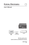
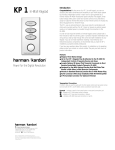
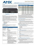
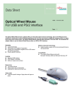
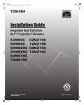
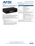
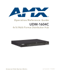
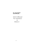
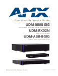
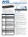
Quick Start Guide
UDM-RX02 Endeleo Multi-Format Receiver
Overview
Configuration
Installed at the display device, the UDM-RX02 (FG-UDM-RX02) converts the signal
received from a UDM Multi-Format Distribution Hub to standard A/V signals (FIG. 1).
The UDM-RX02 is configured via the UDM Hub’s WebConsole. Refer to the UDM
Hub’s Operation/Reference Guide for details.
Rear Panel Components
All of the connectors and ports are located on the rear panel (FIG. 2):
Composite (Pr) port
Composite (Pb) port
UDM HUB port (RJ45) - from an
“OUTPUT” port on the UDM-0102 Composite (Y) port
VGA (HD15) port
S-Video port
CVBS port
Serial port (RJ12)
FIG. 1 UDM-RX02
With all the same features of the UDM-RX01, the UDM-RX02 adds support for
“Common” mode sync, as well as remote power for long cable distance runs.
Compatibility
The UDM-RX02 is compatible for use with the following UDM Hubs:
• UDM-0102 (FG-UDM-0102) - This hub supports Common Synch Mode.
• UDM-0404 (FG-UDM-0404) - This hub supports Common Synch Mode.
• UDM-1604 (FG-UDM-1604C) - This hub supports Common Synch Mode.
• UDM-1604 (FG-UDM-1604) - This hub does not support Common Synch Mode.
In this case, the UDM-RX02 will function, but without Common Synch Mode.
Product Specifications
IR Rx port
IR Tx port
Power connector
RCA audio
(left/right)
SPDIF female Digital Audio port
FIG. 2 UDM-RX02 - rear panel components
UDM Hub Port (RJ45)
UDM-RX02 Specifications
The UDM-RX02 connects to a UDM Hub through a Cat 5/Cat 6 connection. Refer to
the UDM Hub’s Operation/Reference Guide for details.
Power Requirements:
Serial Port
24VDC @ .75A
Note: In most cases the UDM-RX02 is remotely powered
by the UDM Multi-Format Distribution Hub (see Powering
on the UDM-RX02 ).
The Serial port is available for diagnostic and troubleshooting purposes.
The Serial port on the UDM-RX02 is an RJ12 connector, and requires a DB9-to-RJ12
adapter cable (FG-RS01) to connect to a PC for Terminal control.
IR Receiver (IR Rx) Port
Rear Panel Connectors:
The IR Rx port is used to enable user control and the remote compensation of the
video link to the UDM, using the FG-UDM-RC10 and the FG-IR03.
Refer to the Protocols and IR Learning section of the UDM Hub’s Operation/Reference
Guide for details for information on learning a device’s IR commands.
Power Socket:
2.1mm barrel-style DC power socket (female)
UDM Hub (RJ45)
Port:
Provides audio/video transport as well as control via Cat5,
Cat5e or Cat6 to an UDM Hub.
Serial (RJ12) port:
Enables an administrator to control the various functions
to the UDM-RX02 from a command line prompt and terminal connection.
• Requires a DB9-to-RJ12 adapter cable (FG-RS01) to
connect to a PC.
• 9600, 8 bit, No Parity, 1 Stop Bit
IR Transmit (IR Tx) Port
IR Rx Port:
3.5mm stereo input port, for connection of an IR receiver
to allow setup of the UDM-RX02, local compensation
controls, and remote control of centrally located IR
devices.
1.
IR Tx Port:
3.5mm stereo IR Transmitter output port allows one IRcontrolled device (such as a DVD or VCR player) to be
controlled via optional wired IR emitter.
Audio Connectors:
• Black RCA female connector - Digital audio
• White RCA female connector - Analog audio Left
• Red RCA female connector - Analog audio Right
Video Connectors:
• Yellow RCA female connector - CVBS (supports
composite video)
• S-Video - S-video female connector
• VGA - HD15 female connector (supports VGA video)
• Green RCA female connector - Component output: Y
• Blue RCA female connector - Component output: Pb
• Red RCA female connector - Component output: Pr
Operating Environment: • 35°F - 95°F (5°C - 35°C)
• Max. relative humidity - 85% (non-condensing)
The IR Tx port issues IR commands from the UDM-RX02 to a controlled display
device (TV monitor or display). One IR display device can be connected to the UDMRX02 via the IR Tx port, and controlled via the UDM Hub’s WebConsole or via remote
control.
Connecting an IR Device to the IR Tx Port
Connect an IR01 Endeleo IR Emitter Module (FG-IR01) to the IR Tx port on the
UDM-RX02.
Note: Ensure the position of the device corresponds to the position assigned in
the Devices option of the UDM- Hub’s WebConsole.
2.
Run the other end of the IR Emitter cable to the device’s IR sensor, and attach
the IR Emitter to the device’s sensor by removing the cover on the reverse side
of the IR Emitter.
IR commands for each device on the system have to be learned by the UDM-0102 in
order to function properly. Refer to the Protocols and IR Learning section of the UDM
Hub’s Operation/Reference Guide for information on learning a device’s IR
commands.
AUDIO Connectors
The UDM-RX02 provides standard Audio RCA output connectors for S/PDIF for digital
audio, and LEFT/RIGHT for analog audio output (FIG. 2).
VIDEO Connectors
VGA Input at Display Device
1.
2.
3.
Attach one end of the VGA cable to the VGA connector on the UDM-RX02.
Run the other end to the VGA connector on the display device. Connect firmly.
If appropriate connect audio to the audio connectors on the UDM-RX02.
Note: Ensure the UDM Hub port the RX02 is attached to is configured correctly
within the Hub’s configuration software. Also ensure the correct Audio Type
(Analog L/R, S/PDIF, or None) is selected for the relevant input.
Dimensions (HWD):
1" x 8 15/16” x 3 3/8” (25 mm x 227 mm x 85 mm)
Weight:
1.45 lb. (658 g)
Composite Input at Display Device
Certifications:
• CE
• FCC part 15 Class A
1.
Other AMX Equipment:
• RS232 DB9/RJ12 Connection Cable (FG-RS01)
• UDM-RC02 Multi-Format IR Remote Control
(FG-UDM-RC02)
• IR01 IR Emitter Module (FG-IR01)
• IR03 External IR Receiver Module (FG-IR03)
• UDM-PS 24VDC, 750mA Power Supply (FG-UDM-PS)
2.
3.
Attach the composite cable (normally yellow) to the CVBS connector on the
UDM-RX02.
Run the other end of the composite cable to the Composite connector (normally
yellow) on the display device. Connect firmly.
If appropriate connect audio to the audio connectors on the UDM-RX02.
SVideo Input at Display Device
1.
2.
3.
Attach the SVideo cable to the 4-pin S Video connector on the UDM-RX02.
Run the other end of the SVideo cable to the SVideo connector on the display
device. Connect firmly.
If appropriate connect audio to the audio connectors on the UDM-RX02.
Component Input at Display Device
Powering on the UDM-RX02
1.
Attach the Component cables (normally green, blue and red) to the Y (green),
Pb (blue) and Pr (red) connectors on the UDM-RX02.
Run the other end of the Component cable to the Component connectors (normally green, blue and red) on the display device. Connect firmly.
If appropriate connect audio to the audio connectors on the UDM-RX02.
Class
Format
Name
Distance
Composite
720x480
NTSC
300 m / 1000’
The UDM-RX02 may be powered by its hub device through a standard CAT5 cable,
but it may also be powered through an optional 24 VDC power supply (FG-UDM-PS)
intended to augment power for very long cable runs.
To connect the UDM-RX02 to the optional power supply, insert the barrel connector
of the power supply into the power connector on the UDM-RX02 (see FIG. 2).
To power down the UDM-RX02, remove the barrel connector of the power supply
from the power connector and then remove the Ethernet cable from the UDM Hub
connector.
Note: Disconnecting the optional power supply will not power down the UDM-RX02 if
its Ethernet connection to the UDM Hub is intact.
720x576
PAL
300 m / 1000’
System Overview
720x480
480p
300 m / 1000’
720x576
576p
300 m / 1000’
FIG. 3 provides a basic system diagram representing a UDM-0102 Hub, UDM-RX02
Receiver, and connected devices:
2.
3.
Audio & Video Formats/Resolutions/Distance
Audio & Video Formats/Resolutions/Distance
Component
VGA
1280x720
720p
300 m / 1000’
1920x1080
1080i
300 m / 1000’
1920x1080
1080p
300 m / 1000’
640x480
VGA
300 m / 1000’ *
800x600
SVGA
300 m / 1000’ *
1024x768
XGA
300 m / 1000’ *
1280x1024
SXGA
300 m / 1000’ *
1600x1200
UXGA
300 m / 1000’ *
DVD
Video Out
Video In
Audio Out
Connecting an External IR Receiver Module
If passthrough mode (where a device such as a DVD or VCR can be controlled via a
UDM-RC02 Multi-Format IR Remote Control) is required then an IR03 External IR
Receiver Module will be needed to pick up IR controls from the remote control.
Additionally, if the UDM-RX02 is to be compensated via a remote control, then an IR
Receiver Module is also needed.
Video In
Audio Out
Audio In
UDM Hub
Ethernet
(network
Cat5
UDM Receiver
Video Out
Video In
Video Compensation
Video at the Receive end can be compensated using three main methods;
• Using the UDM Hub’s WebConsole
• Using the UDM-RC02 Multi-Format IR Remote Control
• Using a hyper terminal session via the serial connector on the UDM-RX02
(especially effective setup method when using long runs)
Video Out
Audio In
* When using VGA modes with audio enabled, the maximum
cable distance is approximately 200 m / 650’.
Note: The maximum distances indicated above are not absolute, but are
recommended distances that have been tested to deliver video at the specified
resolutions, without significant signal degradation. In particular, lower resolutions
(640 x 480, 720 x 480 and 800 x 600) can often be delivered significantly further than
what is indicated in the table. Refer to the UDM Hub’s Operation/Reference Guide
for additional details on maximum cable distances.
DSS
Audio Out
Audio In
Display
FIG. 3 UDM System Diagram
Additional Documentation
Refer to the UDM-0102 and UDM-RX02 Multi-Format Distribution Hub and Receiver
Operation/Reference Guide (available online at www.amx.com) for detailed
information on configuring the Hub, UDM receivers and source devices.
Connecting the UDM-RX02 Receiver to the UDM Hub
The RJ45 port on the front panel of the UDM-0102 Hub labelled “UDM” supports one
UDM-RX02 Receiver. The UDM-RX02 is then be connected to a display device.
1.
Connect a standard Cat5/6 Ethernet cable to the RJ45 port labelled UDM on
the front panel of the UDM hub.
2.
Connect the other end of the Ethernet cable to the RJ45 port labelled UDM
Hub on the rear panel of the UDM-RX02.
Note: Ensure the UDM Hub port the RX02 is attached to is configured correctly
within the Hub’s configuration software. Also ensure the correct Audio Type
(Analog L/R, S/PDIF, or None) is selected for the relevant input.
UDM HUB Port LEDs
2 LEDs are visible at the UDM Hub port (on the UDM-RX02) when the UDM-0102 is
switched on:
• Green – Connection to UDM-0102 (if Cat 5 removed, LED switches off).
• Amber – Power (as well as comms if uploading protocols etc. the Amber LED
may flicker).
For full warranty information, refer to the AMX Instruction Manual(s) associated with your Product(s).
2/08
©2008 AMX. All rights reserved. AMX and the AMX logo are registered trademarks of AMX.
AMX reserves the right to alter specifications without notice at any time.
3000 RESEARCH DRIVE, RICHARDSON, TX 75082 • 800.222.0193 • fax 469.624.7153 • technical support 800.932.6993 • www.amx.com
93-UDM-RX02
REV: F