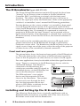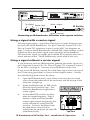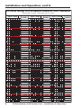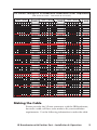
1
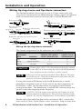
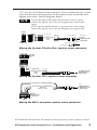
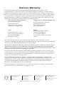
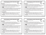
User’s Manual
DISPLAY
POWER
VCR
DVD
Laptop
VOLUME
MAX/
MIN
Extron
MLC 206
MediaLink Controller
Extron
MLC
Extron
IR Broadcaster
Projector
IR Broadcaster
System Switcher and MediaLink Accessory
68-392-02 Rev. B
Printed in the USA
02 02
Introduction
The IR Broadcaster (part #60-272-02)
The Extron Infrared Broadcaster transmits IR signals that have been
“learned” by an Extron system switcher or Extron MediaLink
Controller (MLC) and that are associated with the front panel
functions. This allows other IR controlled devices in the room to
receive the signal put out by the Broadcaster. Refer to the appropriate
switcher’s or controller’s user’s manual for IR learning procedures.
Pressing buttons on the system switcher’s or controller’s front panel,
or on an Extron IR remote control, SCP control pad, or RS-232 host
causes the IR Broadcaster to broadcast an IR command that is associated
with that button/key. For example, if a command to switch the
projector to RGB mode has been “learned” and associated with an
input selection button, when that button is selected from a panel, the
IR remote control, or from the RS-232 host, that learned command is
broadcast.
The switcher or the controller provides power, an IR signal, and a
ground connection to the IR Broadcaster through a special threeconductor custom cable. The Broadcaster should be placed so that its
signal covers a large area of the room, within the range of the projector
or other devices to be controlled by learned commands.
Front and rear panels
The picture below shows the front and rear panels of the IR Broadcaster. Place the dark red lens side (front) of the Broadcaster toward the
room so that the projector (or other device) can receive the IR signals.
For some applications it may be desirable to limit the signal broadcast
range. There is a connector on the IR Broadcaster for use with the
standard IR Emitter. If an Emitter is
Rear
connected to the Broadcaster, the
switcher or controller sends IR signals to
Comm.
Emitter
controlled devices via the IR Emitter, but
not out the Broadcaster’s emitters.
IR BROADCASTER
The IR Broadcaster’s own emitter
devices and the responder LED are
shown in the illustration. The emitters
are not easily seen through the dark
lens, but the responder can be seen
when its LED blinks to indicate that an
IR signal has been broadcasted.
Responder LED
Front
Broadcast Emitters
Installing and Setting Up the IR Broadcaster
The following illustration shows a typically appllication with an
IR Broadcaster connected to a switcher, and it also shows how the
IR Emitter can be used with the Broadcaster.
2
IR Broadcaster with Emitter Port • Introduction
CONTROL
DISP
PWR
DISP
MUTE
MODE
ROOM
1
ROOM
2
1
2
3
4
5
COLOR TINT
BRIGHT CONT
DETAIL
ADJUST
VOLUME
MENU
6
7
NEXT
DISPLAY
INPUT 7
VIDEO
VIDEO
S-VIDEO
S-VIDEO
AUDIO
LL
COMPUTER
IR
RX LEARN
TX
RX
RR
SYSTEM 7SC
Extron System 7SC
Tip (Signal)
Sleeve (Gnd)
White = Signal
IR Emitter
Black = Ground
Connecting an IR Broadcaster, IR Emitter, and a system switcher
Using a signal with a carrier signal
For most applications, a signal that already has a carrier frequency may
be used with the IR Broadcaster. Use pin C from the System 5/5cr/5cr
Plus or System 7SC connector, or pin A on the MLC (see diagrams on
page 7), and use the IR Broadcaster’s default DIP switch settings (switch
9 open) to allow the carrier signal to pass through and be broadcast.
This leaves the signal/no carrier pin available for a projector that uses a
wired remote control. The IR Emitter may not be used in this case.
Using a signal without a carrier signal
If you choose to have the IR Broadcaster generate the carrier signal, use
pin A from the System 5/5cr/5cr Plus or System 7SC connector, or pin C
on the MLC (see page 5). You may use an IR Emitter in this case.
If you use an IR Emitter, connect the white lined signal wire to the tip of
the 2.5 mm plug (provided), as shown in the diagram above. Connect
the solid black ground wire to the sleeve.
1.
Open the IR Broadcaster’s case: remove and save the two small
screws from the underside of the enclosure, and lift the top of the
enclosure straight up.
2.
Inside the Broadcaster, set DIP switch
#9 to the closed position (up). This
forces the Broadcaster to generate a
carrier signal.
3.
Set the other DIP switches to determine the carrier frequency. Page 3
features a table of all the possible
carrier signal output frequencies that
can be selected by setting the DIP
switches. Choose a frequency from
the table that is closest to that
required by the projector (or other IRcontrolled device).
1
2
3
4
5
6
7
8
9
10
ON
Top View
IR Broadcaster with Emitter Port • Installation & Operation
3
Installation and Operation, cont’d
DIP Switch Settings for IR Broadcaster-Generated Carrier Frequencies
(DIP switch 9: closed.
Closed = up,
Open = down,
1 2 3 4 5 6 7 8
Freq.
(kHz)
DIP switch 10: not used.)
Closed = up,
Open = down,
1 2 3 4 5 6 7 8
13,400.00
6,700.00
4,466.70
3,350.00
3,350.00
2,680.00
2,233.30
1,914.30
1,675.00
1,675.00
1,488.90
1,340.00
1,218.20
1,116.70
1,116.68
1,030.80
957.10
893.30
837.50
837.50
788.20
744.40
705.30
670.00
670.00
1 2 3 4 5 6 7 8
Closed = up,
Open = down,
1 2 3 4 5 6 7 8
326.80
319.00
311.60
304.55
304.50
297.80
291.30
285.10
279.20
279.18
273.50
268.00
262.70
257.70
257.70
252.80
248.10
243.60
239.30
239.28
235.10
231.00
227.10
223.33
223.30
1 2 3 4 5 6 7 8
638.10
609.10
582.60
558.33
558.30
536.00
515.40
496.30
478.60
478.58
462.10
446.70
432.30
418.80
418.75
406.10
394.10
382.90
372.23
372.20
362.20
352.60
343.60
335.00
335.00
4
Freq.
(kHz)
Freq.
(kHz)
165.40
163.40
161.40
159.53
159.50
157.60
155.80
154.00
153.20
152.28
150.60
148.90
147.30
145.70
145.65
144.10
142.60
141.10
139.60
139.58
138.10
136.70
135.40
134.00
134.00
1 2 3 4 5 6 7 8
219.70
216.10
212.70
209.40
209.38
206.20
203.00
200.00
197.10
197.05
194.20
191.40
188.70
186.10
186.10
183.60
181.10
178.70
176.33
176.30
174.00
171.80
169.60
167.50
167.50
132.70
131.40
130.10
128.85
128.80
127.60
126.40
125.20
124.10
124.08
122.90
121.80
120.70
119.65
119.60
118.60
117.50
116.50
115.53
115.50
114.50
113.60
112.60
111.70
111.68
IR Broadcaster with Emitter Port • Installation & Operation
DIP Switch Settings for IR Broadcaster-Generated Carrier Frequencies
(DIP switch 9: closed.
Closed = up,
Open = down,
1 2 3 4 5 6 7 8
Freq.
(kHz)
DIP switch 10: not used.)
Closed = up,
Open = down,
1 2 3 4 5 6 7 8
110.70
109.80
108.90
108.10
108.08
107.20
106.30
105.50
104.70
104.70
1 2 3 4 5 6 7 8
Freq.
(kHz)
56.78
55.83
54.93
54.03
53.18
52.35
51.55
50.75
50.00
49.28
1 2 3 4 5 6 7 8
101.53
98.53
95.73
93.05
90.55
88.15
85.90
83.75
81.70
79.75
77.90
76.13
74.45
72.83
71.28
1 2 3 4 5 6 7 8
Closed = up,
Open = down,
1 2 3 4 5 6 7 8
35.28
34.90
34.53
34.18
33.85
33.50
33.18
32.85
32.53
32.20
1 2 3 4 5 6 7 8
48.55
47.85
47.18
46.53
45.90
45.28
44.68
44.08
43.50
42.95
42.40
41.88
41.35
40.85
40.35
1 2 3 4 5 6 7 8
69.80
68.38
67.00
65.68
64.43
63.20
62.03
60.90
59.83
58.78
57.75
Freq.
(kHz)
31.90
31.60
31.30
31.03
30.73
30.45
30.18
29.90
29.65
29.38
29.13
28.88
28.63
28.40
28.15
1 2 3 4 5 6 7 8
39.88
39.40
38.95
38.50
38.08
37.65
37.23
36.83
36.43
36.03
35.65
27.93
27.68
27.45
27.23
27.03
26.80
26.58
26.38
26.18
Making the Cable
Extron provides the 3.5 mm connectors with the IR Broadcaster,
however a cable will have to be made to fit your installation
requirements. Use the following information to make the cable.
IR Broadcaster with Emitter Port • Installation & Operation
5
Installation and Operation
Wiring tip-ring-sleeve and tip-sleeve connectors
The illustration below shows how to wire a 3.5 mm stereo-style (tipring-sleeve) connector for the IR Broadcaster voltage, signal, and ground
wires to connect the System Switcher or MLC to the IR Broadcaster.
1 Unscrew cover.
5 Solder 3 wires.
2 Locate components.
Sleeve (Gnd)
Tip (+12V)
Ring
Sleeve
Ring (Signal)
6 Bend tabs up over cable insulation.
3 Slide cover and heat shrink
Tip
over cable.
Heat Shrink
4 Strip wires and solder ends, and insert in holes.
Ring (Signal)
Tip (+12V)
7 Slide heat shrink over exposed wires, and apply heat.
8 Screw cover onto connector.
Sleeve (Gnd)
Wiring the tip-ring-sleeve connector
The contact assignments for the connector are as follows:
Stereo
connector
part
Function
Tip
System 5cr/5cr Plus,
System 7SC captive
screw connector pin
MLC
captive screw
connector pin
+12 volts
E
E
Signal & carrier
C
A
Sleeve
Ground
B or D
D
CAUTION
Because there will be +12 volts on the tip (from the switcher
or the MLC) it is best to plug the cable to the IR Broadcaster
first, and then into the switcher’s or MLC’s panel.
Ring
If the projector has round jack marked “Wired Remote”, this may
be wired to pin A. Check the documentation that came with the
projector to be sure of this function.
If using the standard IR Emitter with the IR Broadcaster, a similar
procedure is required to put a 2.5 mm, round, tip-sleeve connector on
the Emitter’s cable. See the illustration on page two for IR Emitter
wiring instructions. The Broadcaster’s internal DIP switches must also
be set to select the outgoing carrier frequency.
A 12VDC, 500 mA output is provided on the Comm port of the
System 5/System 5cr/System 5cr Plus, the IR Comm port of the
System 7SC, and the Display/Source Control IR port of the MLC.
For the end of the cable that goes to the switcher or MLC, connect the
wires to the 3.5 mm, 5-pole captive screw connector. Strip no more than
6
IR Broadcaster with Emitter Port • Installation & Operation
1/4” (0.6 cm) of insulation from each wire. Do not solder the tips. Insert
each wire into the correct position on the captive screw connector, and
tighten each screw. See the diagrams below.
To pass through an IR signal that includes a carrier signal,
connect the signal wire to the pin designated for carrier and
signal.
If you want the IR Broadcaster to generate the carrier signal,
connect the signal wire to the pin designated for signal only.
COMM
A
B
C
D
E
Signal only
Gnd
Carrier & signal
Gnd
+12V
Sleeve (Gnd)
Tip (+12V)
To the
IR Broadcaster
(60-272-02)
Ring (Signal)
System 5
Comm port
Tip (+12V)
Sleeve (Gnd)
Wiring the System 5/5cr/5cr Plus’ captive screw connector
E D C B A
IR COMM
System 7
IR Comm
port
A
Signal only
C Carrier & signal
Gnd
D
+12V
E
To IR Broadcaster
with emitter port
(#60-272-02)
Wiring the System 7SC’s captive screw connector
A Modulated IR (signal & carrier)
C Demodulated IR (signal only)
Ground
D
+12VDC output
E
To
IR Broadcaster
with Emitter port
(#60-272-02)
MLC IR
Display/Source
Control port
A B C D E
IR
Wiring the MLC’s one-piece captive screw connector
All trademarks mentioned in this manual are the properties of their respective owners.
IR Broadcaster with Emitter Port • Installation and Operation
7
Extron’s Warranty
Extron Electronics warrants this product against defects in materials and
workmanship for a period of three years from the date of purchase. In the event of
malfunction during the warranty period attributable directly to faulty workmanship
and/or materials, Extron Electronics will, at its option, repair or replace said products
or components, to whatever extent it shall deem necessary to restore said product to
proper operating condition, provided that it is returned within the warranty period,
with proof of purchase and description of malfunction to:
USA, Canada, South America,
and Central America:
Extron Electronics
1230 South Lewis Street
Anaheim, CA 92805, USA
Asia:
Extron Electronics, Asia
135 Joo Seng Road, #04-01
PM Industrial Bldg.
Singapore 368363
Europe, Africa, and the Middle East:
Extron Electronics, Europe
Beeldschermweg 6C
3821 AH Amersfoort
The Netherlands
Japan:
Extron Electronics, Japan
Daisan DMJ Bldg. 6F,
3-9-1 Kudan Minami
Chiyoda-ku, Tokyo 102-0074
Japan
This Limited Warranty does not apply if the fault has been caused by misuse,
improper handling care, electrical or mechanical abuse, abnormal operating conditions
or non-Extron authorized modification to the product.
If it has been determined that the product is defective, please call Extron and ask for an
Applications Engineer at (714) 491-1500 (USA), 31.33.453.4040 (Europe), 65.6383.4400
(Asia), or 81.3.3511.7655 (Japan) to receive an RA# (Return Authorization number). This
will begin the repair process as quickly as possible.
Units must be returned insured, with shipping charges prepaid. If not insured, you
assume the risk of loss or damage during shipment. Returned units must include the
serial number and a description of the problem, as well as the name of the person to
contact in case there are any questions.
Extron Electronics makes no further warranties either expressed or implied with
respect to the product and its quality, performance, merchantability, or fitness for any
particular use. In no event will Extron Electronics be liable for direct, indirect, or
consequential damages resulting from any defect in this product even if Extron
Electronics has been advised of such damage.
Please note that laws vary from state to state and country to country, and that some
provisions of this warranty may not apply to you.
www.extron.com
Extron Electronics, USA
Extron Electronics, Europe
Extron Electronics, Asia
Extron Electronics, Japan
1230 South Lewis Street
Anaheim, CA 92805
USA
714.491.1500
Fax 714.491.1517
Beeldschermweg 6C
3821 AH Amersfoort
The Netherlands
+31.33.453.4040
Fax +31.33.453.4050
135 Joo Seng Road, #04-01
PM Industrial Building
Singapore 368363
+65.6383.4400
Fax +65.6383.4664
Daisan DMJ Building 6F
3-9-1 Kudan Minami
Chiyoda-ku, Tokyo 102-0074 Japan
+81.3.3511.7655
Fax +81.3.3511.7656
© 2002 Extron Electronics. All rights reserved.