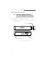
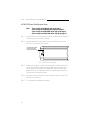
1
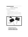
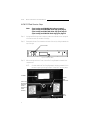
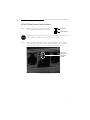
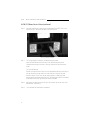
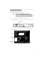
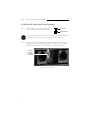
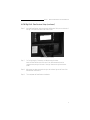
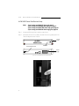
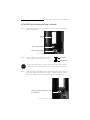
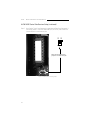
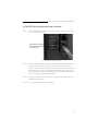
ALPHA™
Wireless
Data Receiver
Installation
Manual
for use with the
ALPHA 215, Big Dot®, 4000 Series, 7000 Series, and 300 Series
Electronic Message Centers
Table of Contents
Installation Instructions ...............................................1
ALPHA 215 .......................................................2
ALPHA Big Dot®..............................................5
ALPHA 4000 Series .........................................8
ALPHA 7000 Series .......................................12
ALPHA 300 Series .........................................16
© 1996 Adaptive Micro Systems
Form No. 9708-8080
8/26/96
NOTE: Due to continuing product innovation,
specifications in this document are subject to
change without notice.
Copyright © 1996 Adaptive Micro Systems, Inc. All rights reserved.
Trademarked names appear throughout this document. Rather than list the names and entities
that own the trademarks or insert a trademark symbol with each mention of the trademarked
name, the publisher states that it is using the names for editorial purposes and to the benefit
of the trademark owner with no intention of improperly using the trademark.
BETA-BRITE and BIG DOT are trademarks of Adaptive Micro Systems, Inc. registered in the
United States Patent and Trademark Office.
ALPHA, AlphaNET, AlphaNET plus, AlphaNET plus II, ALPHAVISION, Automode, EZ KEY II,
EZ95, PowerView, PrintPak, TimeNet, and SMART ALEC are trademarks of Adaptive Micro
Systems, Inc.
ii
ALPHA™ Wireless Data Receiver Installation Manual
Installation Instructions
What’s included in the Data Receiver Kit?
1
1
1
2
2
1
1
Data Receiver
Jumper (In clear bag)
Access Cover Mount (Only used for ALPHA 215 and Big Dot signs)
Access Cover Mount screws (in bag)
Velcro strips (Optional. For flush wall mount where applicable. Not pictured below.)
3-foot Extender Cable (Optional use. Not pictured below. Used to connect the Data
Receiver to an ALPHA 4000 Series or 7000 Series sign when wall mounting either of
these signs.)
Modular Plug (Optional use. Not pictured below. Used to connect the 3-foot Extender
Cable to the cable on the Data Receiver.)
Jumper
Data Receiver (front)
Data Receiver (back) —
shown with Access Cover
Mount attached.
Figure 1: Data Receiver Kit (photos not to scale).
If you are missing any of the above items, contact your ALPHA distributor.
For ALPHA 215 installation, go to page 2.
For ALPHA Big Dot® installation, go to page 5.
For ALPHA 4000 Series installation, go to page 8.
For ALPHA 7000 Series installation, go to page 12.
For ALPHA 300 Series installation, go to page 16.
1
ALPHA™ Wireless Data Receiver Installation Manual
ALPHA 215 Data Receiver Setup
Note:
If you’re using an ALPHA Big Dot® sign, go to page 5.
If you’re using an ALPHA 4000 Series sign, go to page 8.
If you’re using an ALPHA 7000 Series sign, go to page 12.
If you’re using an ALPHA 300 Series sign, go to page 16.
Step 1:
Unplug the ALPHA sign from its outlet or power source. Make sure to unplug the
unit from the outlet, not the back of the sign.
Step 2:
Remove the Access Cover located on the back of the unit, by sliding it towards the
top of the sign:
Access Cover
Figure 2: ALPHA 215 (back).
Step 3:
After removing the Access Cover, find the Two-Prong Receptacle located in the
compartment:
NOTE:
On some models the Two-Prong Receptacle has been removed. If this is
the case on your sign, then go to Step 6. You will NOT use the jumper.
EPROM
Receiver
Cable
RS232 Port
Two-Prong
Receptacle
(This may
not be
present on
some
models.)
Cable
Groove
Figure 3: The compartment under the Access Cover.
2
ALPHA™ Wireless Data Receiver Installation Manual
ALPHA 215 Data Receiver Setup (continued)
Step 4:
Get the Jumper from your Data Receiver Kit. The
Jumper (right) is a small dark piece of plastic.
Jumper top
Jumper bottom
STOP
Step 5:
When installing the Jumper, be careful not to drop it inside the ALPHA 215 case.
If the Jumper falls inside, service may be required to remove it.
Locate the Two-Prong Receptacle that is below the EPROM. If there already is a
jumper over these two prongs, then go to Step 6. Otherwise, place the Jumper
bottom over the two prongs. Then push down until the Jumper is secure:
Place the
Jumper over
these two
prongs.
Figure 4: Where to install the Jumper.
3
ALPHA™ Wireless Data Receiver Installation Manual
ALPHA 215 News Service Setup (continued)
Step 6:
Insert the Data Receiver cable plug into the Receiver Cable RS232 Port on the
back of the sign. Then place the cable in the Cable Groove:
Figure 5: Completed installation.
Step 7:
For Ceiling Hanging, Countertop, and Wall Mounting Brackets:
Install the Data Receiver (with its Access Cover Mount attached) over the
compartment opening on the back of the sign. Remount the sign and restore
power.
For Flush Wall Mounts:
Reinstall the original Access Cover over the compartment opening on the back of
the sign. Remount the sign. Attach one side of the Velcro strips to the Data
Receiver’s Access Cover. Then use the remaining Velcro to attach the Data
Receiver directly to the wall next to the sign. The Data Receiver MUST be installed
horizontally with the LED light facing out. Restore the power.
Step 8:
After power has been restored to the sign, the indicator light on the front of the
Data Receiver should be on.
Step 9:
This completes the Data Receiver installation.
4
ALPHA™ Wireless Data Receiver Installation Manual
ALPHA Big Dot® Data Receiver Setup
Note:
If you’re using an ALPHA 215 sign, go to page 2.
If you’re using an ALPHA 4000 Series sign, go to page 8.
If you’re using an ALPHA 7000 Series sign, go to page 12.
If you’re using an ALPHA 300 Series sign, go to page 16.
Step 1:
Unplug the ALPHA sign from its outlet or power source.
Step 2:
Remove the Access Cover located on the back of the unit, by sliding it towards the
top of the sign:
Access Cover
Figure 6: ALPHA Big Dot® (back).
Step 3:
After removing the Access Cover, find the Two-Prong Receptacle located in the
compartment:
EPROM
Two-Prong
Receptacle
Receiver Cable
RS232Port
Cable
Groove
Figure 7: The compartment under the Access Cover.
5
ALPHA™ Wireless Data Receiver Installation Manual
ALPHA Big Dot® Data Receiver Setup (continued)
Step 4:
Get the Jumper from your Data Receiver Kit. The
Jumper (right) is a small dark piece of plastic.
Jumper top
Jumper bottom
STOP
Step 5:
When installing the Jumper, be careful not to drop it inside the ALPHA Big Dot®
case. If the Jumper falls inside, service may be required to remove it.
Locate the Two-Prong Receptacle that is below the EPROM. If there already is a
jumper over these two prongs, then go to Step 6. Otherwise, place the Jumper
bottom over the two prongs. Then push down until the Jumper is secure:
Place the
Jumper
over these
two prongs.
Figure 8: Where to install the Jumper.
6
ALPHA™ Wireless Data Receiver Installation Manual
ALPHA Big Dot® Data Receiver Setup (continued)
Step 6:
Insert the Data Receiver cable plug into the left Receiver Cable port on the back of
the sign. Then place the cable in the Cable Groove:
Figure 9: Completed installation.
Step 7:
For Ceiling Hanging, Countertop, and Wall Mounting Brackets:
Install the Data Receiver (with its Access Cover Mount attached) over the
compartment opening on the back of the sign. Remount the sign and restore
power.
Step 8:
After power has been restored to the sign, the indicator light on the front of the
Data Receiver should be on.
Step 9:
This completes the Data Receiver installation.
7
ALPHA™ Wireless Data Receiver Installation Manual
ALPHA 4000 Series Data Receiver Setup
Note:
If you’re using an ALPHA 215 sign, go to page 2.
If you’re using an ALPHA Big Dot® sign, go to page 5.
If you’re using an ALPHA 7000 Series sign, go to page 12.
If you’re using an ALPHA 300 Series sign, go to page 16.
Step 1:
Unplug the ALPHA sign from its outlet or power source.
Step 2:
Remove the Access Cover located on the side of the unit, by grasping the Front
Tab and sliding the Access Cover off:
Access
Cover
ALPHA
4000 Series
Communication Ports
Front Tab
Power
supply
Figure 10: ALPHA 4000 Series sign (front & back).
Figure 11: Access Cover removal.
8
ALPHA™ Wireless Data Receiver Installation Manual
ALPHA 4000 Series Data Receiver Setup (continued)
Step 3:
After removing the Access Cover, find the Two-Prong Receptacle located at the
bottom of the EPROM:
EPROM
Two-Prong Receptacle
Three-Prong Receptacle
Figure 12: The compartment under the Access Cover.
Step 4:
Get the Jumper from your Data Receiver Kit. The
Jumper (right) is a small dark piece of plastic.
Jumper top
Jumper bottom
STOP
Step 5:
When installing the Jumper, be careful not to drop it inside the ALPHA 4000
Series case. If the Jumper falls inside. service may be required to remove it.
Locate the Two-Prong Receptacle that is below the EPROM. If there already is a
jumper over these two prongs, then go to Step 6. Otherwise, place the Jumper
bottom over the two prongs. Then push down until the Jumper is secure:
Place the Jumper over these two prongs
(as shown here)
Figure 13: Installing the Two-Prong jumper.
9
ALPHA™ Wireless Data Receiver Installation Manual
ALPHA 4000 Series Data Receiver Setup (continued)
485
Next, find the Three-Prong Receptacle located below the Two-Prong Receptacle. If
the existing jumper is not on the leftmost two pins (for RS232), then remove the
jumper and place it over these two pins:
232
Step 6:
Jumper
Make sure the Three-Prong
jumper is over these two pins.
Figure 14: Installing the Three-prong jumper.
10
ALPHA™ Wireless Data Receiver Installation Manual
ALPHA 4000 Series Data Receiver Setup (continued)
Step 7:
Insert the Data Receiver cable into the bottom Communication Port—the RS232
port—on the back of the sign:
Insert Receiver cable plug
into the bottom RS232 port
(as shown here)
Figure 15: Data Receiver cable installation.
Step 8:
Reinstall the original Access Cover over the compartment opening on the side of
the sign. Remount the sign. Attach one side of the Velcro strips to the Data
Receiver. Then use the remaining Velcro to attach the Data Receiver directly to the
wall next to the sign. Use the 3-foot Extender Cable and Modular Plug to mount
the Data Receiver to the wall. The Data Receiver MUST be installed horizontally
with the LED light facing out. Restore the power.
Step 9:
After power has been restored to the sign, the indicator light on the front of the
Data Receiver should be on.
Step 10: This completes the Data Receiver installation.
11
ALPHA™ Wireless Data Receiver Installation Manual
ALPHA 7000 Series Data Receiver Setup
Note:
If you’re using an ALPHA 215 sign, go to page 2.
If you’re using an ALPHA Big Dot® sign, go to page 5.
If you’re using an ALPHA 4000 Series sign, go to page 8.
If you’re using an ALPHA 300 Series sign, go to page 16.
Step 1:
Unplug the ALPHA sign from its outlet or power source.
Step 2:
Remove the Access Cover located on the side of the unit, by unscrewing the two
screws that hold it in place:
Access Cover
ALPHA
7000 Series
Communication Ports
Power supply
Figure 16: ALPHA 7000 Series sign (front & back).
12
ALPHA™ Wireless Data Receiver Installation Manual
ALPHA 7000 Series Data Receiver Setup (continued)
Step 3:
After removing the Access Cover, find the Two-Prong Receptacle located at the
bottom of the EPROM:
EPROM
Two-Prong Receptacle
Three-Prong Receptacle
Figure 17: The compartment under the Access Cover.
Step 4:
Get the Jumper from your Data Receiver Kit. The
Jumper (right) is a small dark piece of plastic.
Jumper top
Jumper bottom
STOP
Step 5:
When installing the Jumper, be careful not to drop it inside the ALPHA 7000
Series case. If the Jumper falls inside. service may be required to remove it.
Locate the Two-Prong Receptacle that is below the EPROM. If there already is a
jumper over these two prongs, then go to Step 6. Otherwise, place the Jumper
bottom over the two prongs. Then push down until the Jumper is secure:
Place the Jumper over these two prongs
(as shown here)
Figure 18: Installing the Two-Prong jumper.
13
ALPHA™ Wireless Data Receiver Installation Manual
ALPHA 7000 Series Data Receiver Setup (continued)
485
Next, find the Three-Prong Receptacle located below the Two-Prong Receptacle. If
the existing jumper is not on the leftmost two pins (for RS232), then remove the
jumper and place it over these two pins:
232
Step 6:
Jumper
Make sure the Three-Prong
jumper is over these two pins.
Figure 19: Installing the Three-prong jumper.
14
ALPHA™ Wireless Data Receiver Installation Manual
ALPHA 7000 Series Data Receiver Setup (continued)
Step 7:
Insert the Data Receiver cable into the bottom Communication Port—the RS232
port—on the back of the sign:
Insert Receiver cable plug
into the bottom RS232 port
(as shown here)
Figure 20: Data Receiver cable installation.
Step 8:
Reinstall the original Access Cover over the compartment opening on the side of
the sign. Remount the sign. Attach one side of the Velcro strips to the Data
Receiver. Then use the remaining Velcro to attach the Data Receiver directly to the
wall next to the sign. Use the 3-foot Extender Cable and Modular Plug to mount
the Data Receiver to the wall. The Data Receiver MUST be installed horizontally
with the LED light facing out. Restore the power.
Step 9:
After power has been restored to the sign, the indicator light on the front of the
Data Receiver should be on.
Step 10: This completes the Data Receiver installation.
15
ALPHA™ Wireless Data Receiver Installation Manual
ALPHA 300 Series Data Receiver Setup
Note:
If you’re using an ALPHA 215 sign, go to page 2
If you’re using an ALPHA Big Dot® sign, go to page 5.
If you’re using an ALPHA 4000 Series sign, go to page 8.
If you’re using an ALPHA 7000 Series sign, go to page 12.
Step 1:
Unplug the ALPHA sign from its outlet or power source. Make sure to unplug the
unit from the outlet, not the back of the sign.
Step 2:
Insert the Data Receiver cable plug into the right Communications Port—the
RS232 port—on the back side of the sign:
Insert Receiver cable
plug into the right
port (as shown here)
Figure 21: Data Receiver cable installation.
Step 3:
Remount the sign. Attach one side of the Velcro strips to the Data Receiver. Then
use the remaining Velcro to attach the Data Receiver directly to the wall next to
the sign. Use the 3-foot Extender Cable and Modular Plug to mount the Data
Receiver to the wall. The Data Receiver MUST be installed horizontally with the
LED light facing out. Restore the power.
Step 4:
After power has been restored to the sign, the indicator light on the front of the
Data Receiver should be on.
Step 5:
This completes the Data Receiver installation.
16