1
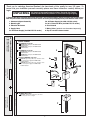
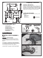
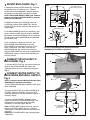
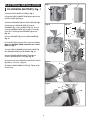
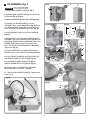
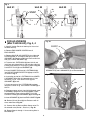
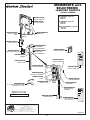
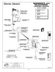
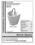
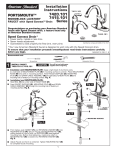
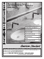
Installation Instructions
Moments Lavatory Faucet
with SELECTRONIC™ Technology
2506.1XX
Product No.'s & Options 1
Certified to comply with ASME A112.18.1M
© 2007 American Standard
Specifications
2
How to Install
2-3
Electrical Hook-up
4-6
Maintenance
7-8
FAQ,s
9
Replacement Parts
10
M968506
NOTE TO INSTALLER: Please give this manual to the customer after installation.
To learn more about American Standard Faucets visit our website at: www.us.amstd.com or U.S.
customer's e-mail us at: [email protected]
For Parts, Service, Warranty or other Assistance,
please call 1-800-442-1902 (In Canada: 1-800-387-0369)
(In Toronto Area only: 1-905-3061093)
Thank you for selecting American-Standard...the benchmark of fine quality for over 100 years. To
ensure that your installation proceeds smoothly--please read these instructions carefully before you
begin.
UNPACKING
All American Standard Faucets Are Water Tested At Our Factory.
Some Residual Water May Remain In The Faucet During Shipping.
1. Remove the fitting and loose items from the carton. The illustration below shows the fitting and all loose items
after they have been removed from the carton. Some items may be packaged partially assembled to other items.
1. Selectronic Spout Assembly
2. Mounting Kit
3. Electrical Enclosure
4. Supply Hose
5a. DC Power Supply (for 2506.155/153 series)
5b. AC Power Supply (for 2506.165/162 series)
5c. 10 ft. Extension Wire (for 2506.175/172 series)
6. Circuit board
7. Mixing Valve ( optional must be ordered separately)
8. Key for vandal resistant aerator
DC POWERED; single inlet
2506.155 with cast spout, 0.5 GPM vandal
resistant aerator.
2506.153 with cast spout, 2.2 GPM vandal
resistant aerator.
B
a
s
e
P
How to order the Selectronic Product
1. Choose Power Supply
2. Choose Desired Spout
MODEL NUMBER:
1
AC POWERED; single inlet
2506.165 with cast spout, 0.5 GPM vandal
resistant aerator.
2506.162 with cast spout, 2.2 GPM vandal
resistant aerator.
r
o
MULTI AC POWERED; single inlet
2506.175 single inlet operates up to 15 units in series
from one AC power supply, 0.5 GPM vandal
resistant aerator.
2506.172 single inlet operates up to 15 units in series
from one AC power supply, 2.2 GPM vandal
resistant aerator.
8
5a
2
5b
d
u
c
t
Base Product
• Single Hole Sink
• Single Inlet
5c
3
6
4
OPTIONAL Mixing Valve
605XTMV Thermostatic mixing valve, flex hoses
Mixing Valve
• 1 and 3 Hole Sinks
• Hot and Cold Inlets
Mixing Valve (optional)
3/8" compression 20" hose length.
7
1
Roughing-in Dimensions
Fig. 1
GENERAL DESCRIPTION:
159mm
(6-1/4)
154mm
(6-1/16)
Electronic faucet with proximity operation. Vandal resistant
solid brass construction single post mounting. Operates on
DC (battery) or AC permanent power. Water pressure range
from 20 to 125 psi. In-line strainer for solenoid is integral.
Single inlet 3/8 compression, built-in checks, and flexible
stainless steel 15" reach inlet hose for spout connection.
126mm
(5)
55.5mm
(2-3/16)
49mm
(2)
81mm
(3-3/16)
32mm (1-1/4)
125mm
(4-7/8)
CODES AND STANDARDS:
These products meet or exceed the following coded
standards:
ANSI A117.1
ASME A112.18.1
CSA B 125
ADA Compliant
NSF 61/Section 9
114mm
(4-1/2)
381mm
(15)
500mm
(20)
1524mm
(60)
3/8" COMP.
TOOLS REQUIRED; Fig. 2
1
2
3
4
5
6
7
Fig. 2
Channel Locks
Adjustable Wrench
Plumbers' Putty or Caulking
Phillips Screwdriver
Flat Blade Screwdriver
Electric Drill & 1/4" Drill Bit
Tape Measure
2
1
3
7
4
6
10'
5
INSTALLATION
1 INSTALL SPOUT ASSEMBLY;
Fig. 1a
Fig. 1
CAUTION
1
Turn off hot and cold water
supplies before beginning
1. Insert WIRES (1), FLEX HOSE (2) and SPOUT
SHANK (3) through center hole of mounting surface.
Fig. 1a.
2
2. Assemble "C" WASHER (4), STAR WASHER (5)
and LOCKNUT (6) onto threads of SPOUT SHANK (7)
from underside of mounting surface. Fig. 1b.
3. Align FAUCET and tighten LOCKNUT (6). Fig. 1b.
Fig. 1b
3
7
4
6
5
2
2 MOUNT ENCLOSURE; Fig. 2
Fig. 2
1. Determine location of ENCLOSURE (1). It must be
located with-in the 14" (356mm) by 21" (533mm)
shaded area shown in Figure 2 in order for electrical
connections from the spout assembly to be made.
NOTE: ENCLOSURE SUPPLY HOSE is 20". Distance
between wall supply and ENCLOSURE (1) must be
taken into consideration.
LAVATORY RIM OR
MOUNTING SURFACE
14"
(356mm)
SUPPLIES
ENCLOSURE
MOUNTING
HOLES
1
2-3/4"
(71mm)
2. Remove 4 screws from COVER (2) and pull off
COVER (2). Hold the ENCLOSURE (1) in desired
location and mark the four mounting hole locations as
shown. Fig. 2.
WASTE
20"
(500mm)
21"
(mm)
1524mm
(60)
3"
(76mm)
3-3/4"
(96mm)
MOUNTING HOLES
3. The ENCLOSURE (1) works best if secured to a wall
stud or cross brace within the wall, using the SCREWS
(3) supplied. If the ENCLOSURE (1) is to be installed on
a tile or plaster wall the ANCHORS (4) and SCREWS
(3) should be used.
3
1
2
4
1
4. For installations on drywall or tiled walls; use
ANCHORS (4) and SCREWS (3) for securing
ENCLOSURE (1) to finished wall. Drill four 1/4" dia.
holes a minimum of 1-3/4" deep. Insert the four
ANCHORS (4) flush with face of the finished wall.
Align the ENCLOSURE (1) and Install the MOUNTING
SCREWS (3). Tighten to secure ENCLOSURE (1) to
mounting surface.
NOTE: If using Mixing Valve (optional) See Sheet
#M968808 for installation instructions.
Fig. 3
3 CONNECT SPOUT HOSE TO
ENCLOSURE; Fig. 3
1
2
1. Connect SUPPLY NUT (1) from spout assembly to
nipple on top of ENCLOSURE (2). Tighten with
adjustable wrench to make a water tight connection.
Fig. 3.
4 CONNECT WATER SUPPLY TO
ENCLOSURE AND WALL SUPPLY;
Fig. 4
Fig. 4
2
NOTE; If using the optional Mixing Valve See Sheet
#M968808 for installation instructions.
1. Insert FIBER WASHER (4) into SUPPLY NUT (1) on
ENCLOSURE (2).
1
4
3
2. Connect SUPPLY NUT (1) on ENCLOSURE (2) to
FLEXIBLE SUPPLY HOSE (3). Tighten to make a
water tight connection. Use two wrenches to tighten if
necessary. Fig. 4.
Fig. 4a
3. Connect FLEXIBLE SUPPLY (3) directly to wall
supply. Connection on FLEXIBLE SUPPLY (3) is 3/8"
compression. Use adjustable wrench to tighten
connection. Do not over tighten. Fig. 4a.
Note: FLEXIBLE SUPPLY (3) measures 20" from the
bottom of the ENCLOSURE (1) base. If additional
supply length is required, installer must purchase parts
separately.
Important: If FLEXIBLE SUPPLY (3) is too long, loop to
avoid kinking.
COLD WATER OR
TEMPERED
WALL SUPPLY
3
3
'JH
&-&$53*$"-*/45"--"5*0/
%$7&34*0/
#"55&3: 'JH
3FNPWF&/$-0463&$07&3 'JH
'FFEUIF8*3&$0//&$5034 UISPVHIUIFUPQ
PG&/$-0463& 'JHB
3FNPWF(30..&5 GSPN&/$-0463 'JH
'JHC
'JHB
'FFEUIFHSBZ4&/4038*3& UISPVHI
(30..&5 GSPN$0//&$503'JHCE
*OTFSUHSBZ4&/4038*3& JOUP41-*51-6( 1VTI41-*51-6( JOUP(30..&5 UPTFBM
'JHE
*OTFSU(30..&5 CBDLJOUP&/$-0463& 'JHD
'JHD
*OTUBMM#"55&3: POUP%$DJSDVJUCPBSE'JHF
/PUF'PS#"55&3:1"$,JOTUBMMBUJPOTFF*OTUBMM
#BUUFSZQBHF
3&%
*OTUBMM$*3$6*5#0"3% JOUP&/$-0463& XJUI4&/4038*3& VOEFS#0"3%'JHD
#-"$,
*OTFSU4&/4038*3&$0//&$503 JOUP
$*3$6*5#0"3%3&$&1503 'JHF
$POOFDUXJSFTGSPN4&/403UP40-&/0*%7"-7&
3FEUP #MBDLUP 'JHD
'JHE
3FQMBDF&/$-0463&$07&3 5JHIUFODPWFS
TDSFXTGJSNMZ
'JHF
"$7&34*0/'JH
$"65*0/
'JH
#FGPSFPQFOJOH&/$-0463&
EJTDPOOFDU"$QPXFSTVQQMZ
3FNPWF&/$-0463&$07&3 'JH
'FFEUIF8*3&$0//&$5034 UISPVHIUIFUPQ
PG&/$-0463& 'JHB
3FNPWF(30..&5 GSPN&/$-0463 'JH
'FFEUIFHSBZ4&/4038*3& UISPVHI
(30..&5 GSPN$0//&$503'JHC*OTFSU
HSBZ4&/4038*3& JOUP41-*51-6( 1VTI
41-*51-6( JOUP(30..&5 UPTFBM'JHF
'JHC
'JHB
*OTFSU(30..&5 CBDLJOUP&/$-0463& 'JHE
3FNPWF41-*51-6( GSPN108&34611-:
(30..&5 *OTFSU108&3$03%$0//&$503
UISPVHI108&34611-:(30..&5 *OTFSU
108&3$03% JOUP41-*51-6( 1VTI
41-*51-6( JOUP108&34611-:(30..&5
UPTFBM'JHH
'JHE
'JHD
*OTFSU108&34611-:$0//&$503 JOUP
3&$&1503 POUIF$*3$6*5#0"3% 'JHD
*OTUBMM$*3$6*5#0"3% JOUP&/$-0463& XJUI4&/4038*3& VOEFS#0"3%'JHE
'JHF
$POOFDUXJSFTGSPN4&/403UP40-&/0*%
7"-7& 3FEUP #MBDLUP 'JHE
3FQMBDF&/$-0463&$07&3 5JHIUFODPWFS
TDSFXTGJSNMZ
'JHH
'JHG
108&3
4611-:
$03% *OTFSU4&/4038*3&$0//&$503 JOUP
$*3$6*5#0"3%3&$&1503 TMPU'JHG
3&%
#-"$,
'JH
6OJU
6OJU
5801*&$&
(30..&5
6OJU
'03"$7&34*0/
'JHB
.6-5*)00,61 'JH 5801*&$&
(30..&5
4FF"$7FSTJPO&MFDUSJDBM)PPLVQGPSGJSTUVOJUPG
UIF.VMUJIPPLVQ
3FNPWF&/$-0463&$07&34GSPNBMM
&/$-0463&4
3FNPWF40-*%#-"$,*/4&35 GSPNSJHIUTJEF
PG&/$-0463&BOESFQMBDFXJUIHSBZ1*&$&
(30..&5 3FQMBDFTPMJECMBDLJOTFSUTPO6OJU
XJUIHSBZ1*&$&(30..&5 5BLFUIFGU&95&/4*0/ GSPN6OJUBOE
JOTUBMMJOUPSJHIUTJEFPG6OJUBOE-FGUTJEFPG6OJU
JOTFBMJOHXJSFJOUP41-*51-6( BTTIPXOJO'JHB
1VTI41-*51-6( JOUP(30..&5 *OTFSU$0//&$503GSPNGU&95&/4*0/ JOUP$*3$6*5#0"3%3&$&1503 UPQPG6OJU
BTTIPXOJO'JH
'FFEUIFHSBZGU&95&/4*0/ UISPVHI306/%
(30..&54 BOE6(30..&54 BTJMMVTUSBUFEBCPWF
'JHC
*OTFSUPUIFSFOEPGGU&95&/4*0/JOUP-08&3
6(30..&5 PG6OJU BQQSPYJNBUFMZGSPN
DPOOFDUPS 'JH1VTI41-*51-6( JOUP
(30..&5 UPTFBM
*OTFSUDPOOFDUPSPGGU&95&/4*0/JOUPMPXFS
SFDFQUPSBTTIPXOJOGJHPO$*3$6*5#0"3% PG
6OJU
3&%
'FFEHSBZTFOTPSXJSFGSPN6OJUUISPVHIVQQFS
6(30..&5 PG6OJU&/$-0463&GSPN
DPOOFDUPS'JH*OTFSUXJSFJOUP41-*51-6( 1VTI41-*51-6( JOUP(30..&5 UPTFBM'JHB
#-"$,
*OTFSU(30..&5 CBDLJOUP&/$-0463&'JHC
3FJOTUBMM$JSDVJU#PBSE JOUP&ODMPTVSFXJUIBMM
XJSFTVOEFS#PBSE'JHC
$POOFDU6OJU3FEBOE#MBDL4FOTPSXJSFT5P
TPMFOPJEWBMWF 3FEUP #MBDLUP 'JHC
3FQFBU4UFQTUISPVHIGPSSFNBJOJOH6OJUTJO
.VMUJ)PPLVQ
."*/5&/"/$&
'JH
%&5&$5*0/
;0/&
)"/%8"4)4&/40301&3"5*0/
'JH
8IFOUIF4FOTPSEFUFDUTBVTFS UIFXBUFS
JNNFEJBUFMZTUBSUTUPGMPX8BUFSGMPXXJMMTUPQ5XP
TFDPOETBGUFSVTFSJTPVUPGTFOTPSSBOHF5IFPGG
EFMBZBMMPXTUIFVTFSUPDPNGPSUBCMZNPWFIJTIBOET
XJUIPVUUIFGMPXDZDMJOHPOUPPGG"TBQSFDBVUJPO B
TBGFUZUJNFSXJMMUVSOPGGUIFXBUFS BGUFSUIFTFOTPSIBT
CFFOCMPDLFEGPSTFDPOET5IFXBUFSXJMMTUBZPGG
VOUJMUIFCMPDLBHFJTSFNPWFEGSPNUIFEFUFDUJPO[POF
%FUFDUJPO;POF NNNN
%FGBVMU4FUBU'BDUPSZ NN
)0850$)"/(&4&/403
3"/(& 'BDUPSZTFUBU 'JH
'JH
4FUUJOHUIF%FUFDUJPO;POF %JTUBODF 3FNPWFDPWFSGSPN&/$-0463&%JTDPOOFDU(3":
4&/4038*3& GSPNDJSDVJUCPBSE UIFOSFDPOOFDU
8IJMFUIF4&/403$0/530--&% JTCMJOLJOH
TMPXMZ QMBDFZPVSIBOEJO NN JOGSPOUPG
UIFTFOTPS'JHB
8IFOUIF-&%TUPQTCMJOLJOHBOETUBZT0/ NPWF
ZPVSIBOEUPUIFEFTJSFEQPTJUJPOBOEIPMEJOQMBDF
VOUJMUIF-&%CFHJOTUPCMJOLBHBJO'JHB
'JHB
'JHB
'JHB
NNNN
0ODFUIF4&/403$0/530--&% CFHJOTUP
CMJOLBHBJO SFNPWFZPVSIBOEGSPNUIFEFUFDUJPO[POF
8IFOUIFGMBTIJOHTUPQT UIFEFUFDUJPOEJTUBODFJTTFU
)0850*/45"--"/%$)"/(&
#"55&3:'JH
6150
NN
#-*/,*/(-&%
'JH
'JH
#-*/,*/(-&%
5PJOTUBMM/FX#"55&3: BMJHOBOEQSFTTEPXO
#"55&3: DPOUBDUTGBDJOHEPXOXBSE JOUPQPTJUJPO
VOUJMUBCTMPDLJOUPQMBDF
#"55&3:)0-%&3
-0$,*/(5"#4
5PSFNPWFUIF#"55&3: TQSFBEUIFUXPUBCTPO
UIF)0-%&3 XJUIZPVSUIVNCT5IF#"55&3: XJMMSFMFBTF
3FNPWFUIF0-%#"55&3: *OTUBMM/&8#"55&3: DPOUBDUTGBDJOH
EPXOXBSE JOUP)0-%&3 BOEQSFTTEPXOJOUP
QPTJUJPOVOUJMUBCTMPDLJOUPQMBDF
4 HOW TO CLEAN FILTER; Fig. 4
CAUTION
Fig.4
Before opening ENCLOSURE
disconnect AC power supply.
1. Remove ENCLOSURE COVER.
2. Close SUPPLY STOP (5) with 4mm Hex wrench.
Note: Keep water flowing out of faucet while shutting off.
3
3. Pull off Red (1) and Black (2) CONNECTORS from
SOLENOID VALVE (3).
4
CLEAN
SCREENS
4. Unthread STRAINER (4) using a 7/16" socket.
5. Pull out the STRAINER (4) and clean with an old
toothbrush. Rinse thoroughly with water.
6. Install the STRAINER (4) back in its place and
tighten with a 7/16" socket.
Caution: do not over tighten strainer.
Note: It is recommended to clean strainer every 6
months.
2
1
5
4
7. Replace ENCLOSURE COVER. Tighten cover
screws firmly.
5 HOW TO CLEAN AND REMOVE
Fig.5
THE AERATOR; Fig. 5
1
1. Remove AERATOR HOUSING (1) with KEY
supplied with faucet.
3
3. Remove AERATOR (2) from HOUSING (1).
2. Clean the AERATOR SCREENS (3) with a old tooth
brush to remove dirt.
4. Rinse Clean with water. Reassemble and install into
spout end. Be sure black seal washer is in place.
2
6 GENERAL CLEANING; Fig. 6
1. For general cleaning use a damp, soft cloth to clean
the spout and the sensor.
2. For cleaning dirt use a soft cloth with diluted dish
washing detergent. Wipe the area using a wet cloth
and dry using a soft cloth.
CAUTION
Do not scratch the sensor when cleaning.
Avoid using anything that may scratch the spout
surface. Never use polishing power, detergent or a
nylon scrub brush. They will damage the surface of the
spout or Sensor.
8
FAQ'S
Q: How will I know if battery needs to be replaced?
A: Valve does not open and sensor blinks 2 times
interrupted by pause for up to 7 days.
Q: Why does the faucet operate the opposite of
expected-Turns On when not in sensor range, but
turns off when in sensor range?
A: Sensor wires to solenoid are reversed. Black to & Red to + is correct.
Q: Why has the flow rate of the faucet reduced
significantly?
A: Check and clean aerator and strainer.
Q: What is the normal operating pressure range?
A: Faucet will operate with supply pressures ranging
from 20-80 psi.
Q: There is no flow out of faucet when I'm in the
sensor range?
A: Check sensor. If sensor blinks 2 times interrupted
by pause, replace battery, or call 1800-442-1902.
9
MOMMENTS with
SELECTRONIC
LAVATORY FAUCETS
PRODUCT NUMBERS
DC POWERED; single inlet
2506.155
2506.153
M923827-YYY0A
2.2 GPM AERATOR
066508-YYY0A
0.5 GPM AERATOR
AC POWERED; single inlet
2506.165
2506.162
MULTI AC POWERED; single inlet
2506.175
2506.172
A923672-0070A
FAUCET SUPPLY
HOSE
M962388-0070A
SENSOR KIT
A950223-007L0A
SENSOR
M962411-0070A
MOUNTING KIT
M950250-0070A
DC SOLENOID
VALVE ASSEMBLY
M962387-0070A
MOUNTING SCREW KIT
A923654-0070A
BATTERY 6VCR-P2
M950251-0070A
AC SOLENOID
VALVE ASSEMBLY
A913202-0070A
WASHER
A922251-0070A
SOLID GROMMET
A924162-0070A
SUPPLY HOSE
A918462-0070A
SOLENOID SCREWS
A950487-0070A
CIRCUIT BOARD DC
M962389-0070A
SOLENOID & SCREWS
A950507-0070A
FILTER
A922267-0070A
ROUND GROMMET
A950509-0070A
SUPPLY STOP
A922265-0070A
10 ft. MULTI EXTENSION WIRE
(for 6057 series only)
A922272-0070A
U GROMMET
A922290-0070A
POWER SUPPLY
GROMMET
Replace the "YYY" with
appropriate finish code
CHROME
002
M950169-0070A
POWER SUPPLY
A950489-0070A
CIRCUIT BOARD
AC & MULTI AC
HOT LINE FOR HELP
For toll-free information and answers to your questions, call:
1 (800) 442-1902
Weekdays 8:00 a.m. to 6:00 p.m. EST
IN MEXICO 01-800-839-12-00
IN CANADA 1-800-387-0369 (TORONTO 1-905-306-1093)
Weekdays 8:00 a.m. to 7:00 p.m. EST
M968506
Product names listed herein are trademarks of American Standard Inc.
10
M968506