1
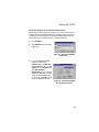
Wireless Mobile Router
User’s Manual
Model WMR1000B
990-1691 Copyright © 2003 American Power Conversion. All rights reserved.
APC is a registered trademark of American Power Conversion.
All other trademarks are the property of their respective owners.
COMPLIANCES
Federal Communication Commission Interference
Statement
This equipment has been tested and found to comply with the limits for a Class B digital
device, pursuant to Part 15 of the FCC Rules. These limits are designed to provide reasonable
protection against harmful interference in a residential installation. This equipment generates,
uses and can radiate radio frequency energy and, if not installed and used in accordance with
the instructions, may cause harmful interference to radio communications. However, there is no
guarantee that interference will not occur in a particular installation. If this equipment does
cause harmful interference to radio or television reception, which can be determined by turning
the equipment off and on, the user is encouraged to try to correct the interference by one of the
following measures:
• Reorient or relocate the receiving antenna
• Increase the separation between the equipment and receiver
• Connect the equipment into an outlet on a circuit different from that to which the
receiver is connected
• Consult the dealer or an experienced radio/TV technician for help
FCC Caution: To assure continued compliance, (example - use only shielded interface cables
when connecting to computer or peripheral devices) any changes or modifications not
expressly approved by the party responsible for compliance could void the user's authority to
operate this equipment. This device complies with Part 15 of the FCC Rules. Operation is subject to the following two conditions: (1) This device may not cause harmful interference, and
(2) this device must accept any interference received, including interference that may cause
undesired operation.
IMPORTANT NOTE:
FCC Radiation Exposure Statement
This equipment complies with FCC radiation exposure limits set forth for an uncontrolled environment. This equipment should be installed and operated with a minimum distance of 20 centimeters (8 inches) between the radiator and your body. This transmitter must not be co-located
or operating in conjunction with any other antenna or transmitter.
1
Industry Canada - Class B
This digital apparatus does not exceed the Class B limits for radio noise emissions from digital
apparatus as set out in the interference-causing equipment standard entitled “Digital Apparatus,” ICES-003 of the Department of Communications.
Cet appareil numérique respecte les limites de bruits radioélectriques applicables aux appareils
numériques de Classe B prescrites dans la norme sur le matériel brouilleur: “Appareils
Numériques,” NMB-003 édictée par le ministère des Communications.
EC Conformance Declaration - Class B
This information technology equipment complies with the requirements of the Council Directive 89/336/EEC on the Approximation of the laws of the Member States relating to Electromagnetic Compatibility and 73/23/EEC for electrical equipment used within certain voltage
limits and the Amendment Directive 93/68/EEC. For the evaluation of the compliance with
these Directives, the following standards were applied:
RFI
*Limit class B according to EN 55022:1998
Emission*Limit class B for harmonic current emission according to EN 61000-3-2/
:
1995
*Limitation of voltage fluctuation and flicker in low-voltage supply system
according to EN 61000-3-3/1995
Immunity*Product family standard according to EN 55024:1998
:
*Electrostatic Discharge according to EN 61000-4-2:1995
(Contact Discharge: ±4 kV, Air Discharge: ±8 kV)
*Radio-frequency electromagnetic field according to EN 61000-4-3: 1996
(80 - 1000 MHz with 1 kHz AM 80% Modulation: 3 V/m)
*Electrical fast transient/burst according to EN 61000-4-4:1995 (AC/DC
power supply: ±1 kV, Data/Signal lines: ±0.5 kV)
*Surge immunity test according to EN 61000-4-5:1995 (AC/DC Line to
Line: ±1 kV, AC/DC Line to Earth: ±2 kV)
*Immunity to conducted disturbances, Induced by radio-frequency fields:
EN 61000-4-6:1996(0.15 - 80 MHz with 1 kHz AM 80% Modulation: 3 V/
m)
*Power frequency magnetic field immunity test according to EN
61000-4-8:1993 (1 A/m at frequency 50 Hz)
*Voltage dips, short interruptions and voltage variations immunity test
according to EN 61000-4-11:1994(>95% Reduction @10 ms, 30%
Reduction @500 ms, >95% Reduction @5000 ms)
LVD:
*EN60950 (A1/1992; A2/1993; A3/1993; A4/1995; A11/1997)
2
CONTENTS
PAGE
1.
ABOUT THE WIRELESS MOBILE ROUTER . . . . . . . . . . . . . . . . . . . . . . 1
Package Contents . . . . . . . . . . . . . . . . . . . . . . . . . . . . . . . . . . . . . . . . . . . . 1
Features and Benefits . . . . . . . . . . . . . . . . . . . . . . . . . . . . . . . . . . . . . . . . . 2
LED Indicators . . . . . . . . . . . . . . . . . . . . . . . . . . . . . . . . . . . . . . . . . . . . . . 3
2.
INSTALLING THE WIRELESS ROUTER . . . . . . . . . . . . . . . . . . . . . . . . 4
Hardware Description . . . . . . . . . . . . . . . . . . . . . . . . . . . . . . . . . . . . . . . . 4
System Requirements . . . . . . . . . . . . . . . . . . . . . . . . . . . . . . . . . . . . . . . . . 6
Installation Procedure . . . . . . . . . . . . . . . . . . . . . . . . . . . . . . . . . . . . . . . . 7
3.
CONFIGURING CLIENT TCP/IP . . . . . . . . . . . . . . . . . . . . . . . . . . . . . . . . 9
Installing TCP/IP . . . . . . . . . . . . . . . . . . . . . . . . . . . . . . . . . . . . . . . . . . . . 9
Windows 95/98/Me/NT . . . . . . . . . . . . . . . . . . . . . . . . . . . . . . . . . . . . . . . 9
Windows 2000 . . . . . . . . . . . . . . . . . . . . . . . . . . . . . . . . . . . . . . . . . . . . . 10
Setting Up TCP/IP . . . . . . . . . . . . . . . . . . . . . . . . . . . . . . . . . . . . . . . . . . 12
Configuring Your Computer in Windows 95/98/Me . . . . . . . . . . . . . . . . 13
DHCP IP Configuration . . . . . . . . . . . . . . . . . . . . . . . . . . . . . . . . . . . . . . 13
Obtain IP Settings from Your Wireless Mobile Router
15
Configuring Your Computer in Windows NT 4.0 . . . . . . . . . . . . . . . . . . 16
DHCP IP Configuration . . . . . . . . . . . . . . . . . . . . . . . . . . . . . . . . . . . . . . 16
Obtain IP Settings From Your Wireless Mobile Router
18
Configuring Your Computer in Windows 2000 . . . . . . . . . . . . . . . . . . . 20
DHCP IP Configuration . . . . . . . . . . . . . . . . . . . . . . . . . . . . . . . . . . . . . . 20
Configuring Your Computer in Windows XP . . . . . . . . . . . . . . . . . . . . . 21
DHCP IP Configuration . . . . . . . . . . . . . . . . . . . . . . . . . . . . . . . . . . . . . . 21
Configuring a Macintosh Computer . . . . . . . . . . . . . . . . . . . . . . . . . . . . 22
DHCP IP Configuration . . . . . . . . . . . . . . . . . . . . . . . . . . . . . . . . . . . . . . 22
Manual IP Configuration (for all Windows OS) . . . . . . . . . . . . . . . . . . . 24
Verifying Your TCP/IP Connection . . . . . . . . . . . . . . . . . . . . . . . . . . . . 26
4.
CONFIGURING THE WIRELESS MOBILE ROUTER . . . . . . . . . . . . . . 27
Browser Configuration . . . . . . . . . . . . . . . . . . . . . . . . . . . . . . . . . . . . . . 27
Disable Proxy Connection . . . . . . . . . . . . . . . . . . . . . . . . . . . . . . . . . . . . 28
Internet Explorer (5 or above) . . . . . . . . . . . . . . . . . . . . . . . . . . . . . . . . . 28
Internet Explorer (for Macintosh) . . . . . . . . . . . . . . . . . . . . . . . . . . . . . . 28
Navigating the Web Browser Interface . . . . . . . . . . . . . . . . . . . . . . . . . . 29
Making Configuration Changes . . . . . . . . . . . . . . . . . . . . . . . . . . . . . . . . 29
Setup Wizard . . . . . . . . . . . . . . . . . . . . . . . . . . . . . . . . . . . . . . . . . . . . . . 31
Time Zone . . . . . . . . . . . . . . . . . . . . . . . . . . . . . . . . . . . . . . . . . . . . . . . . 31
i
CONTENTS
PAGE
Broadband Type . . . . . . . . . . . . . . . . . . . . . . . . . . . . . . . . . . . . . . . . . . . . 32
Cable Modem . . . . . . . . . . . . . . . . . . . . . . . . . . . . . . . . . . . . . . . . . . . . . 33
Fixed-IP xDSL . . . . . . . . . . . . . . . . . . . . . . . . . . . . . . . . . . . . . . . . . . . . . 33
PPPoE xDSL . . . . . . . . . . . . . . . . . . . . . . . . . . . . . . . . . . . . . . . . . . . . . . 34
PPTP (Point-to-Point Tunneling Protocol) . . . . . . . . . . . . . . . . . . . . . . . 35
Big Pond . . . . . . . . . . . . . . . . . . . . . . . . . . . . . . . . . . . . . . . . . . . . . . . . . 36
Advanced Setup . . . . . . . . . . . . . . . . . . . . . . . . . . . . . . . . . . . . . . . . . . . . 37
System . . . . . . . . . . . . . . . . . . . . . . . . . . . . . . . . . . . . . . . . . . . . . . . . . . . 38
Time Zone . . . . . . . . . . . . . . . . . . . . . . . . . . . . . . . . . . . . . . . . . . . . . . . . 38
Password Settings . . . . . . . . . . . . . . . . . . . . . . . . . . . . . . . . . . . . . . . . . . 39
Remote Management . . . . . . . . . . . . . . . . . . . . . . . . . . . . . . . . . . . . . . . . 40
WAN . . . . . . . . . . . . . . . . . . . . . . . . . . . . . . . . . . . . . . . . . . . . . . . . . . . . 41
Dynamic IP . . . . . . . . . . . . . . . . . . . . . . . . . . . . . . . . . . . . . . . . . . . . . . . 41
Point-to-Point Over Ethernet (PPPoE) . . . . . . . . . . . . . . . . . . . . . . . . . . 42
Point-to-Point Tunneling Protocol (PPTP) . . . . . . . . . . . . . . . . . . . . . . . 43
Static IP . . . . . . . . . . . . . . . . . . . . . . . . . . . . . . . . . . . . . . . . . . . . . . . . . . 44
BigPond . . . . . . . . . . . . . . . . . . . . . . . . . . . . . . . . . . . . . . . . . . . . . . . . . . 45
Domain Name Servers (DNS) . . . . . . . . . . . . . . . . . . . . . . . . . . . . . . . . . 46
LAN . . . . . . . . . . . . . . . . . . . . . . . . . . . . . . . . . . . . . . . . . . . . . . . . . . . . . 47
Wireless . . . . . . . . . . . . . . . . . . . . . . . . . . . . . . . . . . . . . . . . . . . . . . . . . . 48
Encryption . . . . . . . . . . . . . . . . . . . . . . . . . . . . . . . . . . . . . . . . . . . . . . . . 49
Network Address Translation (NAT) . . . . . . . . . . . . . . . . . . . . . . . . . . . 52
Address Mapping . . . . . . . . . . . . . . . . . . . . . . . . . . . . . . . . . . . . . . . . . . . 52
Virtual Server . . . . . . . . . . . . . . . . . . . . . . . . . . . . . . . . . . . . . . . . . . . . . . 53
HTTP: 80, FTP: 21, Telnet: 23, and POP3: 110 . . . . . . . . . . . . . . . . . . . 53
Special Applications . . . . . . . . . . . . . . . . . . . . . . . . . . . . . . . . . . . . . . . . 54
Firewall . . . . . . . . . . . . . . . . . . . . . . . . . . . . . . . . . . . . . . . . . . . . . . . . . . 56
Access Control . . . . . . . . . . . . . . . . . . . . . . . . . . . . . . . . . . . . . . . . . . . . . 56
MAC Filtering Table . . . . . . . . . . . . . . . . . . . . . . . . . . . . . . . . . . . . . . . . 58
URL Blocking . . . . . . . . . . . . . . . . . . . . . . . . . . . . . . . . . . . . . . . . . . . . . 59
Schedule Rule . . . . . . . . . . . . . . . . . . . . . . . . . . . . . . . . . . . . . . . . . . . . . 60
Intrusion Detection . . . . . . . . . . . . . . . . . . . . . . . . . . . . . . . . . . . . . . . . . 62
DMZ (Demilitarized Zone) . . . . . . . . . . . . . . . . . . . . . . . . . . . . . . . . . . . 63
DDNS (Dynamic DNS) Settings . . . . . . . . . . . . . . . . . . . . . . . . . . . . . . . 64
UPnP (Universal Plug and Play) Setting . . . . . . . . . . . . . . . . . . . . . . . . . 65
ii
CONTENTS
PAGE
Tools . . . . . . . . . . . . . . . . . . . . . . . . . . . . . . . . . . . . . . . . . . . . . . . . . . . . 66
Tools - Configuration Tools . . . . . . . . . . . . . . . . . . . . . . . . . . . . . . . . . . 66
Tools - Firmware Upgrade . . . . . . . . . . . . . . . . . . . . . . . . . . . . . . . . . . . . 67
Tools - Reset . . . . . . . . . . . . . . . . . . . . . . . . . . . . . . . . . . . . . . . . . . . . . . 68
Status . . . . . . . . . . . . . . . . . . . . . . . . . . . . . . . . . . . . . . . . . . . . . . . . . . . . 69
5.
TROUBLESHOOTING . . . . . . . . . . . . . . . . . . . . . . . . . . . . . . . . . . . . . . . 71
6.
SPECIFICATIONS . . . . . . . . . . . . . . . . . . . . . . . . . . . . . . . . . . . . . . . . . . . 74
7.
WARRANTY . . . . . . . . . . . . . . . . . . . . . . . . . . . . . . . . . . . . . . . . . . . . . . . 75
8.
APPENDIX: COMPATIBILITY WITH APC’S . . . . . . . . . . . . . . . . . . 76
TRAVELPOWER CASE AND TRAVELPOWER ADAPTER
iii
FIGURE
PAGE
Figure 1. Wireless Mobile Router LEDs . . . . . . . . . . . . . . . . . . . . . . . . . . . . . . . .
Figure 2. Wireless Mobile Router Rear Panel Connectors . . . . . . . . . . . . . . . . . .
Figure 3. Connecting the Wireless Mobile Router . . . . . . . . . . . . . . . . . . . . . . . .
Figure 4. Windows 95/98/Me/NT Select Network Component Type Screen . . . .
Figure 5. Windows 95/98/Me/NT Select Network Protocol Screen . . . . . . . . . . .
Figure 6. Windows 2000 Select Network Component Type Screen . . . . . . . . . . .
Figure 7. Windows 2000 Select Network Protocol Screen . . . . . . . . . . . . . . . . . .
Figure 8. Windows 95/98/Me Network Screen . . . . . . . . . . . . . . . . . . . . . . . . . . .
Figure 9. Windows 95/98/Me TCP/IP Properties Screen . . . . . . . . . . . . . . . . . . .
Figure 10. Windows 95/98/Me Run Screen. . . . . . . . . . . . . . . . . . . . . . . . . . . . . .
Figure 11. Windows 95/98/Me IP Configuration Screen . . . . . . . . . . . . . . . . . . .
Figure 12. Windows NT 4.0 Control Panel Screen . . . . . . . . . . . . . . . . . . . . . . . .
Figure 13. Windows NT 4.0 Network Screen . . . . . . . . . . . . . . . . . . . . . . . . . . . .
Figure 14. Command Prompt Screen. . . . . . . . . . . . . . . . . . . . . . . . . . . . . . . . . . .
Figure 15. Updated Command Prompt Screen . . . . . . . . . . . . . . . . . . . . . . . . . . .
Figure 16. Local Area Connection 1 Status Screen . . . . . . . . . . . . . . . . . . . . . . . .
Figure 17. Local Area Connection 2 Status Screen . . . . . . . . . . . . . . . . . . . . . . . .
Figure 18. Apple Menu (System Preferences Selected) . . . . . . . . . . . . . . . . . . . .
Figure 19. Apple System Preferences Screen . . . . . . . . . . . . . . . . . . . . . . . . . . . .
Figure 20. Apple Network Screen . . . . . . . . . . . . . . . . . . . . . . . . . . . . . . . . . . . . .
Figure 21. TCP/IP Properties Screen . . . . . . . . . . . . . . . . . . . . . . . . . . . . . . . . . . .
Figure 22. TCP/IP Properties Gateway Screen . . . . . . . . . . . . . . . . . . . . . . . . . . .
Figure 23. TCP/IP Properties DNS Configuration Screen . . . . . . . . . . . . . . . . . .
Figure 24. Login Screen. . . . . . . . . . . . . . . . . . . . . . . . . . . . . . . . . . . . . . . . . . . . .
Figure 25. Overview Screen with Setup Wizard and Advanced Setup Options . .
Figure 26. Select Time Zone Screen . . . . . . . . . . . . . . . . . . . . . . . . . . . . . . . . . . .
Figure 27. Broadband Type Selection Screen . . . . . . . . . . . . . . . . . . . . . . . . . . . .
Figure 28. Cable Modem Setup Screen . . . . . . . . . . . . . . . . . . . . . . . . . . . . . . . . .
Figure 29. Fixed-IP xDSL Setup Screen . . . . . . . . . . . . . . . . . . . . . . . . . . . . . . . .
Figure 30. PPPoE xDSL Setup Screen . . . . . . . . . . . . . . . . . . . . . . . . . . . . . . . . .
Figure 31. PPTP (Point-to-Point Tunneling Protocol) Setup Screen. . . . . . . . . . .
Figure 32. Big Pond Setup Screen . . . . . . . . . . . . . . . . . . . . . . . . . . . . . . . . . . . . .
Figure 33. Set System Time Zone Screen . . . . . . . . . . . . . . . . . . . . . . . . . . . . . . .
Figure 34. Password Setup Screen. . . . . . . . . . . . . . . . . . . . . . . . . . . . . . . . . . . . .
Figure 35. Remote Management Setup Screen . . . . . . . . . . . . . . . . . . . . . . . . . . .
Figure 36. Dynamic IP Setup Screen. . . . . . . . . . . . . . . . . . . . . . . . . . . . . . . . . . .
Figure 37. Point-to-Point Over Ethernet (PPPoE)Setup Screen . . . . . . . . . . . . . .
Figure 38. Point-to-Point Tunneling Protocol (PPTP) Setup Screen. . . . . . . . . . .
Figure 39. Static IP Address Setup Screen . . . . . . . . . . . . . . . . . . . . . . . . . . . . . .
Figure 40. BigPond Setup Screen . . . . . . . . . . . . . . . . . . . . . . . . . . . . . . . . . . . . .
Figure 41. DNS Setup Screen . . . . . . . . . . . . . . . . . . . . . . . . . . . . . . . . . . . . . . . .
Figure 42. LAN Setup Screen . . . . . . . . . . . . . . . . . . . . . . . . . . . . . . . . . . . . . . . .
Figure 43. Channel and SSID Setup Screen . . . . . . . . . . . . . . . . . . . . . . . . . . . . .
Figure 44. 64-Bit Encryption Setup Screen . . . . . . . . . . . . . . . . . . . . . . . . . . . . . .
Figure 45. 128-Bit Encryption Setup Screen . . . . . . . . . . . . . . . . . . . . . . . . . . . . .
Figure 46. Address Mapping Setup Screen . . . . . . . . . . . . . . . . . . . . . . . . . . . . . .
Figure 47. Virtual Server Setup Screen . . . . . . . . . . . . . . . . . . . . . . . . . . . . . . . . .
iv
3
4
7
9
10
11
11
13
14
15
15
16
17
18
19
20
21
22
22
23
24
25
25
30
30
31
32
33
33
34
35
36
38
39
40
41
42
43
44
45
46
47
48
50
51
52
53
FIGURE
Figure 54.
Figure 55.
Figure 56.
Figure 57.
Figure 58.
Figure 59.
Figure 60.
Figure 61.
Figure 62.
Figure 63.
Figure 64.
Figure 65.
PAGE
Edit Schedule Rule Setup Screen . . . . . . . . . . . . . . . . . . . . . . . . . . . . .
Intrusion Detection Setup Screen . . . . . . . . . . . . . . . . . . . . . . . . . . . . .
DMZ Setup Screen . . . . . . . . . . . . . . . . . . . . . . . . . . . . . . . . . . . . . . . .
DDNS Setup Screen . . . . . . . . . . . . . . . . . . . . . . . . . . . . . . . . . . . . . . .
UPnP Setup Screen. . . . . . . . . . . . . . . . . . . . . . . . . . . . . . . . . . . . . . . .
Configuration Tools Setup Screen . . . . . . . . . . . . . . . . . . . . . . . . . . . .
Firmware Upgrade Screen . . . . . . . . . . . . . . . . . . . . . . . . . . . . . . . . . .
Tools Reset Screen . . . . . . . . . . . . . . . . . . . . . . . . . . . . . . . . . . . . . . . .
Status Screen . . . . . . . . . . . . . . . . . . . . . . . . . . . . . . . . . . . . . . . . . . . .
Command Prompt Screen. . . . . . . . . . . . . . . . . . . . . . . . . . . . . . . . . . .
Command Prompt IP Configuration Screen. . . . . . . . . . . . . . . . . . . . .
Command Prompt Ethernet Adapter Screen . . . . . . . . . . . . . . . . . . . .
TABLES
Table 1
Table 2
Table 3
Table 4
Table 5
61
62
63
64
64
65
66
67
68
69
72
73
PAGE
LED Indicators. . . . . . . . . . . . . . . . . . . . . . . . . . . . . . . . . . . . . . . . . . . . .
Wireless Mobile Router Rear Panel Connectors . . . . . . . . . . . . . . . . . . .
Advanced Setup Features . . . . . . . . . . . . . . . . . . . . . . . . . . . . . . . . . . . .
Status Screen Elements . . . . . . . . . . . . . . . . . . . . . . . . . . . . . . . . . . . . . .
Specifications. . . . . . . . . . . . . . . . . . . . . . . . . . . . . . . . . . . . . . . . . . . . . .
v
3
5
37
70
74
ABOUT THE WIRELESS MOBILE ROUTER
Thank you for purchasing APC’s Wireless Mobile Router. This device is
a powerful yet simple communication device for connecting a local area
network (LAN) to the internet.
Package Contents
After unpacking the Wireless Mobile Router, check the contents of the
box to ensure that it contains the following:
•
Wireless Mobile Router (model number: WMR1000B)
•
One AC Power adapter
•
One USB power cord for connecting to APC’s Travel Power Adapter
•
One CAT-6 Ethernet cable
•
One driver and utility installation and documentation compact disk
(CD)
•
Quick Installation Guide
Please contact the reseller if any item is missing or damaged.
Note: The purchaser must use APC's Wireless Mobile Router in full
compliance with Federal Law and guidelines established by the
local service provider.
1
About the Wireless Mobile Router
Features and Benefits
2
•
Internet connection to DSL or cable modem via a
10/100 Mbps ethernet port
•
IEEE 802.11b compliant – interoperable with multiple vendor’s
equipment
•
Provides roaming within 802.11b WLAN environment
•
Dynamic Host Configuration Protocol (DHCP) for dynamic Internet
Protocol (IP) configuration, and Domain Naming Servicer/Service
(DNS) for domain name mapping
•
Stateful Packet Inspection (SPI) firewall with client privileges, hacker
prevention, and NAT
•
Network Address Translation (NAT) also enables multi-user access
with a single-user account, and virtual server functionality (providing
protected access to Internet services such as web, File Transfer
Protocol (FTP), mail and Telnet)
•
Virtual Private Network (VPN) support using PPTP, L2TP or IPSec
pass-through
•
Easy setup through a web browser on any operating system that
supports TCP/IP
•
Compatible with all popular Internet applications
•
Integrates with APC’s TravelPower Case
•
USB or AC powered.
LED Indicators
APC’s Wireless Mobile Router includes status Light Emitting Diode
(LED) indicators, as defined in Figure 1 and Table 1.
Figure 1. Wireless Mobile Router LEDs
Table 1. LED Indicators
LED
Status
Description
Wireless
Link
TX/
RX
Flashing
(Green)
The device is transmitting or
receiving data through wireless
links.
Ethernet
Status
LNK/
ACT
On (Orange)
The device has established a valid
100 Mbp/s ethernet link.
On (Green)
The device has established a valid
10 Mbp/s ethernet link.
Flashing
The device is transmitting or
receiving data on the ethernet LAN
On (Green)
Power is being supplied.
Power (PWR)
3
Installing the Wireless Router
INSTALLING THE WIRELESS ROUTER
Before installing the APC’s Wireless Mobile Router, ensure the items
listed under “Package Contents” are available. If any item is missing or
damaged, contact the place of purchase or a local APC distributor. Also
ensure that all the necessary cabling is in place before installing the
Wireless Mobile Router.
Hardware Description
APC’s Wireless Mobile Router can be connected to the internet using a
Wide Area Network (WAN) port. Use the WAN port for connection to a
10BASE-T/100BASE-TX ethernet LAN. It can auto-negotiate the
operating speed to 10/100 Mbps, and the mode to half/full duplex. This
port can be connected directly to a PC or to a server equipped with an
ethernet network interface card via a crossover cable, or to a networking
device such as an ethernet hub or switch. This WAN port can also be
used for a connection to a Digital Suscriber Line (DSL) or cable modem
(WAN). Refer to Figure 2 and Table 2 for a description of the two
connectors on the Wireless Mobile Router.
Power
Power Connector
Connector
WAN Port
RJ-45
Port
Figure 2. Wireless Mobile Router Rear Panel Connectors
4
Hardware Description
Table 2. Wireless Mobile Router Rear Panel Connectors
Item
Description
Power
Connector
Connect the power adapter (included) to this connector.
Warning: Using the wrong type of power adapter or
power adapter plug may damage the adapter.
WAN
Connector
Fast Ethernet (WAN) port (RJ-45). Connect a device
(such as a PC, hub or switch) from the local area network
to this port.
Note: If using the RELOAD button located at the bottom, the Wireless
Mobile Adapter performs a power reset. If the button is held
depressed for over 5 seconds, all LEDs will illuminate and the
factory settings will be restored.
5
Installing the Wireless Router
System Requirements
•
TCP/IP network protocol installed on each PC that needs to access
the internet.
•
JAVA enabled web browser such as Microsoft Internet Explorer 5.0
or Netscape.
•
Input Power Requirements
Mobile: USB power cord (provided).
Note:
Ideally to be used with APC’s TravelPower Case. For more
information, go to www.apc.com and select Mobile
Accessories.
Home/Small Business: Power adapter, 120 volts, North America
only.
•
Computer (Wireless Enabled)
Mobile:
Laptops - Centrino enabled or 802.11b compliant card bus
Handheld - Wi-Fi enabled
Home/Small Business:
Desktop computers - 802.11b wireless enabled network interface
card or USB wireless card.
•
Existing LAN/Internet Access
Mobile:
Using existing DHCP enabled LAN port. Example: Hotel rooms with
high-speed internet access or LAN port in a conference room.
Home/Small Business:
Internet access and settings provided by an Internet Service
Provided (ISP). Example: Digital Suscriber Line (DSL), cable
modem, etc.
Note: In case of existing network, use the Mobile Settings
previously defined.
6
Installation Procedure
Installation Procedure
The Wireless Mobile Router can be positioned at any convenient
location in the home or office. No special wiring or cooling requirements
are needed. However, APC recommends the following guidelines:
•
•
Keep the Wireless Mobile Router away from heat.
Do not place the Wireless Mobile Router in a dusty or wet
environment.
To install the Wireless Mobile Router (Figure 3), proceed as follows:
1. Connect the Category 6 (CAT6) ethernet cable provided with the
Wireless Mobile Router to the LAN/WAN port on the network
(providing internet access, e.g., xDSL modem or cable modem) to
the WAN connector at the rear of the Router.
Caution: Do not plug a phone jack connector into any RJ-45 port, as
this may damage the Router. Instead, use twisted-pair cables having
RJ-45 connectors that conform to Federal Communications
Commission (FCC) standards.
.
Internet
Internet
Access
Device
Wireless Cable/DSL
Broadband Router
Notebook with
Wireless PC Card
Desktop PC with
Wireless PCI Adapter
Figure 3. Connecting the Wireless Mobile Router
7
Installing the Wireless Router
2. Connect power to the Wireless Mobile Router as follows:
Mobile - connect one end of the USB power cable (provided) to the
Router power connector. Connect the other end of the USB cable to
the USB connector on the notebook computer being used, or to the
TravelPower® Adapter (if using APC’s TravelPower Case).
Home Office/Small Business - connect the AC power adapter
(provided) to the Wireless Mobile Router. Connect the AC power
adapter to an AC power source (wall outlet, APC surge protector,
DC/AC inverter, etc).
Rotate both antennas on the side of the Wireless Mobile Router to the
desired position. For more effective coverage, position antennas along
different axes; for example around 45 to 90 degrees apart. Try to place
the Wireless Mobile Router in a position that is located in the center of
the wireless network. Normally, the higher the antenna is placed, the
better the performance. Ensure the Wireless Mobile Router location
provides optimal reception throughout the home or office.
Computers equipped with a wireless adapter can communicate with
each other as an independent wireless LAN by configuring each
computer to the same radio channel. However, the Wireless Mobile
Router can provide access to the wired/wireless LAN or to the Internet
for all wireless workstations. Each wireless PC in this network
infrastructure can talk to any computer in the wireless group via a radio
link, or access other computers or network resources in the wired LAN
infrastructure or over the Internet via the Wireless Mobile Router.
The wireless infrastructure configuration not only extends the
accessibility of wireless PCs to the wired LAN, but also increases the
effective wireless transmission range for wireless PCs by retransmitting
incoming radio signals through the Wireless Mobile Router.
Ensure that the clients are configured to the same SSID (default: APC),
and that encryption and wireless communication are configured.
For additional information about SSID and encryption, refer to the
“Advanced Setup” section in this manual.
8
Configuring Client TCP/IP
CONFIGURING CLIENT TCP/IP
If TCP/IP protocols have not previously been installed on the client PCs,
refer to the following section. For information on how to configure a TCP/
IP address on a PC, refer to “Setting Up TCP/IP”.
Installing TCP/IP
Windows 95/98/Me/NT
1. Click Start/Settings/Control Panel.
2. Double-click the Network icon and select the Configuration tab in
the Network screen (Figure 4).
3. Click the Add button.
4. Double-click the Protocol icon.
Figure 4. Windows 95/98/Me/NT
Select Network Component Type
Screen
9
Configuring Client TCP/IP
5. In the Select Network Protocol screen (Figure 5) select Microsoft
in the Manufacturers list. Select TCP/IP in the Network Protocols
list. Click the OK button to return to the Network screen.
Figure 5. Windows 95/98/Me/NT Select
Network Protocol Screen
6. The TCP/IP protocol will be listed in the Network window. Click OK.
The operating system may prompt for a restart of the system. Click
Yes at this prompt - the computer will shut down and restart.
Windows 2000
1. Click the Start button and choose Settings: click the Network and
Dial-up Connections icon.
2. Double-click the Local Area Connection icon; click the Properties
button on the General tab.
3. Click the Install button.
10
Installing TCP/IP
4. Double-click Protocol (refer to Figure 6).
Figure 6. Windows 2000 Select Network
Component Type Screen
5. In the Select Network Protocol screen (Figure 7), choose Internet
Protocol (TCP/IP). Click the OK button to return to the Network
screen.
Figure 7. Windows 2000 Select Network Protocol Screen
6. The TCP/IP protocol will be listed in the Network screen. Click OK
to complete the installation procedure.
11
Setting Up TCP/IP
To access the Internet through the Wireless Mobile Router, first
configure the network settings of the computers on the LAN to use the
same IP subnet as the Wireless Mobile Router. The default network
settings for the Wireless Mobile Router are:
Gateway IP Address: 192.168.2.1
Subnet Mask:
255.255.255.0
Note:
These settings may be changed to suit individual network
requirements, but at least one computer must be configured
as described in this section to access the Wireless Mobile
Router’s web configuration interface. See “Configuring the
Wireless Mobile Router” for information on configuring the
Wireless Mobile Router.
If TCP/IP has not previously been configured on the computer, refer to
“Configuring Client TCP/IP”.
The IP address of the connected client PC should be 192.168.2.x (where
x means 2–254). Set the IP address for client PCs either by
automatically obtaining an IP address from the Wireless Mobile Router’s
DHCP service, or by manual configuration.
12
Setting Up TCP/IP
Configuring Your Computer in Windows 95/98/Me
The instructions here may not exactly match your version of Windows,
as these steps and screenshots were created using Windows 98.
Windows 95 and Windows Millennium Edition are very similar, but not
identical, to Windows 98.
DHCP IP Configuration
1. From the Windows desktop, click Start/Settings/Control Panel.
2. In the Control Panel, locate and double click the Network icon.
3. On the Network window
Configuration tab (Figure 8),
double-click the TCP/IP entry
for your network card.
Figure 8. Windows 95/98/Me
Network Screen
13
Configuring Client TCP/IP
4. Click the IP Address tab
(Figure 9).
5. Click “Obtain an IP address“.
6. Click on the Gateway tab and
verify the Gateway field is
blank. If there are IP
addresses listed in the
Gateway section, highlight
each one and click Remove
until the section is empty.
Figure 9. Windows 95/98/Me
TCP/IP Properties Screen
7. Click the OK button to close the TCP/IP Properties window.
8. On the Network Properties Window, click the OK button to save
these new settings.
9. Windows may prompt for the original Windows installation disk or
additional files. Check for the files at c:\windows\options\cabs, or
insert the Windows CD-ROM into the CDROM drive and check for
the correct file location, e.g., D:\win98, D:\win9x. (if D is the letter of
your CD-ROM drive).
10. Windows may prompt to restart the PC. If so, click the Yes button. If
Windows does not prompt to restart the computer, do so to insure
the settings.
14
Setting Up TCP/IP
Obtain IP Settings from Your Wireless Mobile Router
Now that the computer has been configured to connect to the Router, it
needs to obtain new network settings. By releasing old IP settings and
renewing them with settings from the Wireless Mobile Router, this will
also verify that the computer has been configured correctly.
1. Click Start/Run.
2. Type WINIPCFG and click OK
(Figure 10).
Figure 10. Windows 95/98/Me
Run Screen
3. From the drop-down menu
(Figure 11), select your
network card. Click Release
and then Renew. Verify your IP
address is now 192.168.2.xxx,
your Subnet Mask is
255.255.255.0 and your Default
Gateway is 192.168.2.1. These
values confirm that the Router
is functioning. Click OK to close
the IP Configuration window.
Figure 11. Windows 95/98/Me
IP Configuration Screen
15
Configuring Client TCP/IP
Configuring Your Computer in Windows NT 4.0
DHCP IP Configuration
1. From the Windows desktop click Start/Settings/Control Panel
(Figure 12).
2. Double-click the
Network icon.
Figure 12. Windows NT 4.0 Control
Panel Screen
16
Setting Up TCP/IP
3. Click on the
Protocols tab
(Figure 13).
4. Double-click
TCP/IP Protocol
icon.
5. Click on the IP
Address tab.
6. In the Adapter
drop-down list, be
sure your Ethernet
adapter is selected.
7. Click on “Obtain an
IP address from a
DHCP server”.
Figure 13.
Windows NT 4.0 Network Screen
8. Click OK to close the window.
9. Windows may copy files and will then prompt to restart your system.
Click Yes; your computer will shut down and restart.
17
Configuring Client TCP/IP
Obtain IP Settings From Your Wireless Mobile Router
Now that you have configured your computer to connect to the Wireless
Mobile Router, it needs to obtain new network settings. By releasing old
IP settings and renewing them with settings from the Wireless Mobile
Router, this will also verify that you have configured your computer
correctly.
1. On the Windows desktop, click Start/Programs/Command Prompt,
the Command Prompt screen (Figure 14) will be displayed.
2. In the Command Prompt screen, type IPCONFIG /RELEASE and
press the <ENTER> key.
Figure 14. Command Prompt Screen
18
Setting Up TCP/IP
3. Type IPCONFIG /RENEW and press the <ENTER> key. The
updated Command Prompt screen (Figure 15) will be displayed.
Verify that your IP Address is now 192.168.2.xxx, your Subnet Mask
is 255.255.255.0 and your Default Gateway is 192.168.2.1. These
values confirm that the Wireless Mobile Router is functioning.
Figure 15. Updated Command Prompt Screen
4. Type EXIT and press <ENTER> to close the Command Prompt
screen.
19
Configuring Client TCP/IP
Configuring Your Computer in Windows 2000
DHCP IP Configuration
1. Access Network settings by clicking Start/Settings/Control Panel.
2. Double-click the Network and Dial-up Connections icon.
3. Double-click the Local Area
Connection icon for the
ethernet adapter connected to
the Wireless Mobile Router.
When the Status dialog box
screen (Figure 16), click the
Properties button.
4. In the Local Area Connection
Properties box, verify the box
next to Internet Protocol
(TCP/IP) is checked. Highlight
Internet Protocol (TCP/IP),
and click the Properties
button.
Figure 16. Local Area
Connection 1 Status Screen
5. Select Obtain an IP address automatically to configure your
computer for DHCP. Click the OK button to save this change and
close the Properties screen.
6. Click the OK button again to save these new changes.
7. Reboot the PC.
8. To obtain new network settings see “Obtain IP Settings from Your
Wireless Mobile Router”.
20
Setting Up TCP/IP
Configuring Your Computer in Windows XP
DHCP IP Configuration
The following instructions assume you are running Windows XP with the
default interface. If using the Classic interface (where the icons and
menus look like previous Windows versions), please follow the
instructions for Windows 2000.
1. Access Network settings
by clicking Start/Control
Panel, select Network
and Internet
Connections. Click on
the Network
Connections icon.
2. Double-click the Local
Area Connection icon
for the Ethernet adapter
connected to the Wireless
Mobile Router. Click the
Properties button.
Figure 17. Local Area Connection
2 Status Screen
3. In the Local Area Connection Properties box, verify the box next
to Internet Protocol (TCP/IP) is checked. Highlight Internet
Protocol (TCP/IP); click the Properties button.
4. Select Obtain an IP address automatically to configure your
computer for DHCP. Click the OK button to save this change and
close the Properties window.
5. Click the OK button again to save these new changes.
6. Reboot the PC.
21
Configuring Client TCP/IP
Configuring a Macintosh Computer
DHCP IP Configuration
The instructions here may not exactly match the operating system being
used as these steps and screenshots were created using Mac OS 10.2.
Mac OS 7.x and above are similar, but may not be identical to Mac OS
10.2.
Follow these instructions:
1. Pull down the Apple Menu
.
Click System Preferences
(Figure 18).
2. Double-click the Network icon
in the Systems Preferences
screen (Figure 19) and the
Network screen (Figure 20)
will be displayed.
Figure 18. Apple Menu (System
Preferences Selected)
Figure 19. Apple System Preferences Screen
22
Setting Up TCP/IP
3. If Using DHCP Server is
already selected in the
Configure field, the
computer is already
configured for DHCP. If
not, select this option.
Figure 20. Apple Network Screen
4. The new settings are shown on the TCP/IP tab. Verify the IP
Address is 192.168.2.xxx, the Subnet Mask is 255.255.255.0 and
the Default Gateway is 192.168.2.1. These values confirm that the
computer is set up for DHCP use.
5. Close the Network screen.
The computer is configured to connect to the Wireless Mobile Router.
23
Configuring Client TCP/IP
Manual IP Configuration (for all Windows OS)
The instructions here may not exactly match your version of Windows as
these steps and screenshots were created in Windows 98. The setup
steps of Manual IP Configuration in Windows 95, Windows Me, Windows
NT, and Windows 2000, are similar, but not identical, to Windows 98.
1. Check Specify an IP
address on the IP Address
tab. Enter an IP address
based on the default
network 192.168.2.x (where
x is between 2 and 254), and
use 255.255.255.0 for the
Subnet mask (Figure 21).
Figure 21. TCP/IP Properties
Screen
24
Setting Up TCP/IP
2. Select the Gateway tab
(Figure 22), add the IP
address of the Wireless
Mobile Router (default:
192.168.2.1) in the New
Gateway field; click Add.
Figure 22. TCP/IP Properties
Gateway Screen
3. Select the DNS
Configuration tab (Figure
23), enter the IP address for
the Wireless Mobile Router;
click Add. This automatically
relays DNS requests to the
DNS server(s) provided by
your ISP. Otherwise, add
specific DNS servers into the
DNS Server Search Order
field; click Add.
4. After finishing TCP/IP setup,
click OK. Reboot the
computer. Set up other PCs
on the LAN according to the
procedures defined above.
Figure 23. TCP/IP Properties
DNS Configuration Screen
25
Configuring Client TCP/IP
Verifying Your TCP/IP Connection
After installing the TCP/IP communication protocols and configuring an
IP address in the same network as the Wireless Mobile Router, use the
Ping command to ensure the computer has successfully connected to
the Wireless Mobile Router, as follows:
1. In an MS-DOS window, enter the Ping command:
ping 192.168.2.1
If a message similar to the following appears, a
communication link between your computer and the Wireless
Mobile Router has been successfully established.
Pinging 192.168.2.1 with 32 bytes of data:
Reply from 192.168.2.1: bytes=32 time=2ms TTL=64
2. If you get the following message, there may be something
wrong in your installation procedure. Check the following
items in sequence:
Pinging 192.168.2.1 with 32 bytes of data:
Request timed out.
a. Is the ethernet cable correctly connected between the
Wireless Mobile Router and the wireless computer?
The RJ-45 port LED on the Wireless Mobile Router and the
Link LED of the network card on the computer must be on.
b. Is TCP/IP properly configured on your computer?
If the IP address of the Wireless Mobile Router is
192.168.2.1, the IP address of the computer must be from
192.168.2.2 to 192.168.2.254 and the default gateway
must be 192.168.2.1. Also ensure that all clients are
configured same SSID, and encryption for wireless
communications is set up.
If you can successfully Ping the Wireless Mobile Router
you are now ready to connect to the internet.
26
Configuring the Wireless Mobile Router
CONFIGURING THE WIRELESS MOBILE ROUTER
The Wireless Mobile Router can be configured by any Java-supported
browser, including Internet Explorer 5.0 or above. Using the web
management interface, you can configure the Wireless Mobile Router
and view statistics to monitor network activity.
Note:
Before attempting to configure the Wireless Mobile Router,
and if you have access to the internet, please go to
www.apc.com, and download the latest firmware version.
Before attempting to log into the Wireless Mobile Router’s web-based
Administration, please verify the following.
1. The browser is configured properly (see below).
2. Any firewall or security software that may be running is disabled.
3. Confirm that the Link LED where the computer is plugged into the
Wireless Mobile Router is active. If the Link LED is not lit – try
another cable until a good link is established.
Browser Configuration
Confirm the browser is configured for a direct connection to the
internet. This is configured through the options/preference
section of the browser.
27
Configuring the Wireless Mobile Router
Disable Proxy Connection
Verify that the HTTP Proxy feature of the web browser is disabled. This
is so that the browser will be able to view the Wireless Mobile Router
configuration pages. The following steps are for Internet Explorer:
Internet Explorer (5 or above)
1. Open Internet Explorer. Click Tools, and select Internet Options.
2. In the Internet Options screen, click the Connections tab.
3. Click the LAN Settings button.
4. Clear all the check boxes; click OK to save these LAN settings.
5. Click OK to close the Internet Options window.
Internet Explorer (for Macintosh)
1. Open Internet Explorer and click the Stop button. Click Explorer/
Preferences.
2. In the Internet Explorer Preferences screen, under Network,
select Proxies.
3. Uncheck all check boxes and click OK.
28
Navigating the Web Browser Interface
The Wireless Mobile Router’s management interface features a Setup
Wizard and an Advanced Setup section. Use the Setup Wizard to
quickly set up the Wireless Mobile Router for use with a cable modem or
DSL modem.
Advanced setup supports more advanced functions such as: hacker
attack detection, IP and MAC address filtering, intrusion detection,
virtual server setup, virtual DMZ hosts, and other advanced functions.
Making Configuration Changes
Configurable parameters have a dialog box or a drop-down list. Once a
configuration change has been made on a page, be sure to click the
Apply or Next button at the bottom of the page to enable the new
setting.
Note:
To ensure proper screen refresh after a command entry,
ensure that Internet Explorer 5.0 is configured as follows:
Under the menu Tools/Internet Options/General/
Temporary Internet Files/Settings, the setting for Check
for newer versions of stored pages, should be set to
“Every visit to the page.”
29
Configuring the Wireless Mobile Router
To access the Wireless Mobile
Router’s management interface,
enter the Wireless Mobile Router IP
address in your web browser (http://
192.168.2.1), click LOGIN and the
Login screen (Figure 24) will be
displayed.
Figure 24. Login Screen
By default, there is no password. APC highly recommends the user
setup a password for increased security (see Password Setting in the
Advanced Setup section).
The home page (Figure 25) displays the Setup Wizard and Advanced
Setup options.
Figure 25. Overview Screen with Setup
Wizard and Advanced Setup Options
30
Setup Wizard
Setup Wizard
Time Zone
Click on the Setup Wizard button (Figure 25). The screen prompts you
to choose your Time Zone (Figure 26).
For accurate timing of client filtering and log events, you need to set the
time zone. Select your time zone from the drop-down list, and click
Next.
Figure 26. Select Time Zone Screen
31
Configuring the Wireless Mobile Router
Broadband Type
Select the type of broadband connection that you have from your
sevice provider (Figure 27).
For a cable modem connection see the following page. For a Fixed-IP
xDSL connection see “Fixed-IP xDSL”, for a PPPoE xDSL
connection, see “PPPoE xDSL”, for a PPTP connection, see “PPTP
(Point-to-Point Tunneling Protocol)”, and for BigPond connection,
see “BigPond”.
Figure 27. Broadband Type Selection Screen
32
Setup Wizard
Cable Modem
Your ISP may have given you a host name. If so, enter it into the field
shown in Figure 28.
Click Finish to complete the setup. The Status page will open to allow
you to view the connection status, as well as other information. See
“Status” for details.
Figure 28. Cable Modem Setup Screen
Fixed-IP xDSL
Some xDSL Internet Service Providers may assign a fixed (static) IP
address (see Figure 29). If you have been provided with this information,
choose this option and enter the assigned IP address, gateway IP
address, DNS IP addresses, and subnet mask. Click Finish to
complete the setup.
Figure 29. Fixed-IP xDSL Setup Screen
33
Configuring the Wireless Mobile Router
PPPoE xDSL
Enter the PPPoE User Name and Password assigned by your service
provider in the screen shown in Figure 30. The Service Name is
normally optional, but may be required by some service providers.
Leave the Maximum Transmission Unit (MTU) at the default value
(1454) unless you have a particular reason to change it.
Enter a Maximum Idle Time (in minutes) to define a maximum period
of time for which the Internet connection is maintained during inactivity. If
the connection is inactive for longer than the Maximum Idle Time, it will
be dropped. (Default: 10)
Enable the Auto-reconnect option to automatically re-establish the
connection as soon as you attempt to access the Internet again. Click
FINISH to complete the setup.
Figure 30. PPPoE xDSL Setup Screen
34
Setup Wizard
PPTP (Point-to-Point Tunneling Protocol)
Point-to-Point Tunneling Protocol is a common connection method used
for xDSL connections in Europe. It can be used to join different physical
networks using the Internet as an intermediary.
If you have been provided with the information requested on the screen
(Figure 31), enter the assigned IP address, subnet mask, default
gateway IP address, user ID and password, and PPTP Gateway.
The MTU (Maximum Transmission Unit) governs the maximum size of
the data packets. Leave this on the default value (1460) unless you
have a particular reason to change it.
Enter a Maximum Idle Time (in minutes) to define a maximum period
of time for which the Internet connection is maintained during inactivity. If
the connection is inactive for longer than the Maximum Idle Time, it will
be dropped. (Default: 10)
Enable the Auto-reconnect option to automatically re-establish the
connection as soon as you attempt to access the Internet again.
Click Finish to complete the setup. (Refer to “Point-to-Point Tunneling”
for additional details.
Figure 31. PPTP (Point-to-Point
Tunneling Protocol) Setup Screen
35
Configuring the Wireless Mobile Router
Big Pond
If you use the BigPond Internet Service, available in Australia, enter the
user name, password and service name for BigPond authentication.
Click Finish to complete the setup (Figure 32).
Figure 32. Big Pond Setup Screen
36
Advanced Setup
Advanced Setup
Use the web management interface to define system parameters,
manage and control the Wireless Mobile Router and its ports, or monitor
network conditions. The Table 3 outlines the selections available from
this program.
Table 3. Advanced Setup Features
Menu
Description
System
Sets the local time zone, the password for administrator access,
and the IP address of a PC that will be allowed to manage the
Wireless Mobile Router remotely.
WAN
Specifies the Internet connection type:
• Dynamic IP host configuration and the physical MAC address of
each media interface
• PPPoE configuration
• PPTP
• Static IP and ISP gateway address
• BigPond (Internet service available in Australia)
• Specifies DNS servers to use for domain name resolution.
LAN
Sets the TCP/IP configuration of the Wireless Mobile Router’s LAN
interface and all DHCP clients.
Wireless
Configures the radio frequency, SSID, and encryption for wireless
communications.
NAT
Shares a single ISP account with multiple users, sets up virtual
servers.
Firewall
Configures a variety of security and specialized functions,
including: Access Control, Hacker Prevention, and DMZ.
DDNS
Dynamic DNS provides users on the Internet with a method to tie
their domain name(s) to computers or servers.
UPnP
With Universal Plug and Play, a device can automatically
dynamically join a network, obtain an IP address, communicate its
capabilities, and learn about the presence and capabilities of other
devices. Devices can then directly communicate with each other.
This further enables peer-to-peer networking.
Tools
Contains options to backup & restore the current configuration,
restore all configuration settings to the factory defaults, update
system firmware, or reset the system.
Status
Provides WAN connection type and status, firmware and hardware
version numbers, system IP settings, as well as DHCP, NAT, and
Firewall information.
Displays the number of attached clients, the firmware versions, the
physical MAC address for each media interface, and the hardware
version and serial number.
Shows the security and DHCP client log.
37
Configuring the Wireless Mobile Router
System
Time Zone
Set the time zone and time server for the Wireless Mobile Router
(Figure 33). This information is used for log entries and client access
control.
Check Enable Automatic Time Server Maintenance to automatically
maintain the Wireless Mobile Router’s system time by synchronizing with
a public time server over the internet. Then configure two different time
servers by selecting the options in the Primary Server and Secondary
Server fields.
Figure 33. Set System Time Zone Screen
38
Advanced Setup
Password Settings
Use this menu (Figure 34) to restrict access based on a password. By
default, there is no password. For security you should assign one before
exposing the Wireless Mobile Router to the internet.
Passwords can contain from 3–12 alphanumeric characters and are not
case sensitive.
Note:
If your password is lost, or you cannot gain access to the user
interface, press the RELOAD button on the back of the
device (holding it down for at least five seconds) to restore
the factory defaults. (The default is no password.)
Figure 34. Password Setup Screen
39
Configuring the Wireless Mobile Router
Enter a maximum Idle Time Out (in minutes) to define a maximum
period of time for which the login session is maintained during inactivity.
If the connection is inactive for longer than the maximum idle time, it will
perform system logout, and you have to login to the web management
system again. (Default: 0 minute)
Remote Management
Remote Management (Figure 35) allows a remote PC to configure,
manage, and monitor the Wireless Mobile Router using a standard web
browser. Check Enable and enter the IP address of the remote host.
Click APPLY.
Note:
If you specify 0.0.0.0 as this IP address, any host can
manage the Wireless Mobile Router.
Figure 35. Remote Management Setup Screen
40
Advanced Setup
WAN
Specify the WAN connection type provided by your Internet Service
Provider, then click More Configuration to enter detailed configuration
parameters for the selected connection type.
Dynamic IP
When setting up a Dynamic IP address (Figure 36), the Host Name is
optional, but may be required by some ISPs. The default MAC address
is set to the WAN’s physical interface on the Wireless Mobile Router. Use
this address when registering for internet service, and do not change it
unless required by the ISP. If the ISP used the MAC address of an
ethernet card as an identifier when first setting up your broadband
account, only connect the PC with the registered MAC address to the
Wireless Mobile Router and click the Clone MAC Address button. This
will replace the current Wireless Mobile Router MAC address with the
already registered Ethernet card MAC address.
Figure 36. Dynamic IP Setup Screen
41
Configuring the Wireless Mobile Router
If you are unsure of which PC was originally set up by the broadband
technician, call your ISP and request they register a new MAC address
for your account. Register the default MAC address of the Wireless
Mobile Router.
Point-to-Point Over Ethernet (PPPoE)
Enter the PPPoE User Name and Password assigned by your Service
Provider (see Figure 37). The Service Name is normally optional, but
may be required by some service providers.
The MTU (Maximum Transmission Unit) governs the maximum size of
the data packets. Leave this at the default value (1492) unless you
have a particular reason to change it.
Enter a Maximum Idle Time (in minutes) to define a maximum period
of time for which the Internet connection is maintained during inactivity. If
the connection is inactive for longer than the Maximum Idle Time, it will
be dropped. (Default: 0 minute)
Enable the Auto-reconnect option to automatically re-establish the
connection as soon as you attempt to access the internet again.
Figure 37. Point-to-Point Over Ethernet
(PPPoE)Setup Screen
42
Advanced Setup
Point-to-Point Tunneling Protocol (PPTP)
Point-to-Point Tunneling Protocol (PPTP) can be used to join different
physical networks using the Internet as an intermediary. Using the above
screen allows client PCs to establish a normal PPTP session and
provides hassle-free configuration of the PPTP client on each client PC.
Enter the PPTP user ID, Password, Host Name and Service IP
address, and then the assigned IP address and subnet mask (usually
supplied by your ISP), Figure 38.
The MTU (Maximum Transmission Unit) governs the maximum size of
the data packets. Leave this on the default value (1460) unless you have
a particular reason to change it.
Enter a maximum Idle Time Out (in minutes) to define a maximum
period of time for which the PPTP connection is maintained during
inactivity. If the connection is inactive for longer than the Maximum Idle
Time, it will be dropped.
Enable the Auto-reconnect option to automatically re-establish the
connection as soon as you attempt to access the Internet again.
Figure 38. Point-to-Point Tunneling
Protocol (PPTP) Setup Screen
43
Configuring the Wireless Mobile Router
Static IP
If your Internet Service Provider has assigned a fixed IP address, enter
the assigned address and subnet mask for the Wireless Mobile
Router, then enter the gateway address of your ISP (Figure 39).
You may need a fixed address if you want to provide Internet services,
such as a web server or FTP server.
Figure 39. Static IP Address Setup Screen
44
Advanced Setup
BigPond
BigPond is a service provider in Australia that uses a “heartbeat” system
to maintain the internet connection. Configure the built-in client with your
user name, password and service name to get on line (Figure 40). You
might have the Authentication Service Name as “login-server” for a
universal configuration.
Figure 40. BigPond Setup Screen
45
Configuring the Wireless Mobile Router
Domain Name Servers (DNS)
Domain Name Servers map numerical IP addresses to the equivalent
domain name (e.g., www.apc.com). Your ISP should provide the IP
address of one or more domain name servers. Enter those addresses in
this screen (Figure 41).
Figure 41. DNS Setup Screen
46
Advanced Setup
LAN
•
LAN IP – Use the LAN menu (Figure 42) to configure the LAN IP
address for the Wireless Mobile Router and to enable the DHCP
server for dynamic client address allocation.
•
Lease Time - Set a period for the lease time, if required. For home
networks, this may be set to Forever, which means there is no time
limit on the IP address lease.
•
IP Address Pool – A dynamic IP start address may be specified,
e.g. 192.168.2.100 (default value). Once this start IP address has
been assigned, IP addresses from 192.168.2.100 to 192.168.2.199
will be part of the dynamic IP address pool. IP addresses from
192.168.2.2 to 192.168.2.99, and 192.168.2.200 to 192.168.2.254
will be available as static IP addresses.
Do not include the address of the Wireless Mobile Router in the client
address pool. Also remember to configure your client PCs for dynamic
IP address allocation.
Figure 42. LAN Setup Screen
47
Configuring the Wireless Mobile Router
Wireless
To configure the Wireless Mobile Router as a wireless access point for
wireless clients (either stationary or roaming), all you need to do is
define the radio channel, the Service Set Identifier (SSID), and
encryption options (Figure 43 - Note: The figures not numbered on the
following page are provided to show better details of the fields on this
screen).
Channel and SSID
You must specify a common radio channel and SSID (Service Set ID)
to be used by the Wireless Mobile Router and all of your wireless
clients. Be sure you configure all of your clients to the same values.
SSID: This should be set to the same value as other wireless devices in
the network. (Default: apc)
Note:
The SSID is case sensitive and can consist of up to 32
alphanumeric characters.
Figure 43. Channel and SSID Setup Screen
48
Advanced Setup
Transmission Rate: Set the data rate transmitted from
the Wireless Mobile Router. The lower the data rate, the
longer the transmission distance.
(Default: Fully Automatic)
Basic Rate: The highest rate specified is the rate the
Wireless Mobile Router will use when transmitting
broadcast/multicast and management frames.
Available options are: All (1, 2, 5.5, 11 Mbps) and 1, 2 Mbps.
Default: All (1, 2, 5.5,11Mbps)
Channel: The radio channel through which the Wireless Mobile
Router communicates with PCs in its BSS. (Default: Auto)
Note:
The available channel settings are limited by local
regulations.
Broadcast SSID: Broadcasting the SSID on the wireless
network for easy connection with client PCs.
(Default: Disable)
Encryption
If you are transmitting sensitive
data across wireless channels,
you should enable Wired
Equivalent Privacy (WEP)
encryption. Encryption requires
you to use the same set of encryption/decryption keys for the
Wireless Mobile Router and all of your wireless clients. You can choose
between standard 64-bit or the more robust 128-bit encryption.
(Default: Disabled)
49
Configuring the Wireless Mobile Router
You may automatically generate encryption keys or manually enter the
keys. For automatic 64-bit security (Figure 44), enter a pass phrase and
click Generate. Four keys will be generated. Choose a key from the
drop-down list or accept the default key. Automatic 128-bit security
generates a single key (Figure 45).
Figure 44. 64-Bit Encryption Setup Screen
If you use encryption, configure the same keys used for the Wireless
Mobile Router on each of your wireless clients. Note that Wired
Equivalent Privacy (WEP) protects data transmitted between wireless
nodes, but does not protect any transmissions over your wired network
or over the internet.
50
Advanced Setup
Figure 45. 128-Bit Encryption Setup Screen
51
Configuring the Wireless Mobile Router
Network Address Translation (NAT)
From this section you can configure the Address Mapping, Virtual
Server, and Special Application features that provide control over the
port openings in the Wireless Mobile Router’s firewall. This section can
be used to support several Internet based applications such as VPN
Address Mapping
Address mapping (Figure 46) allows one or more public IP addresses to
be shared by multiple internal users. Enter the Public IP address you
wish to share into the Global IP field. Enter a range of internal IP
addresses that will share the global IP.
Figure 46. Address Mapping Setup Screen
52
Advanced Setup
Virtual Server
If you configure the Wireless Mobile Router as a virtual server, remote
users accessing services such as web or FTP at your local site via
public IP addresses can be automatically redirected to local servers
configured with private IP addresses. In other words, depending on the
requested service (TCP/UDP port number), the Wireless Mobile Router
redirects the external service request to the appropriate server (located
at another internal IP address).
The more common TCP service ports include:
HTTP: 80, FTP: 21, Telnet: 23, and POP3: 110
Figure 47. Virtual Server Setup Screen
53
Configuring the Wireless Mobile Router
Special Applications
Some applications, such as internet gaming, videoconferencing,
Internet telephony and others, require multiple connections. These
applications cannot work with Network Address Translation (NAT)
enabled. If you need to run applications that require multiple
connections, use the following screen (Figure 48) and Table 3 to specify
the additional public ports to be opened for each application.
Figure 48. Special Applications Setup Screen
Specify the public port number normally associated with an application
in the Trigger Port field. Set the protocol type to TCP or UDP, then
enter the ports that the application requires.
Special application connections can also be achieved by selecting the
application type and item number in the Popular applications field, and
clicking the Copy to button to easily specify the port numbers. Then set
the protocol type to TCP or UDP.
54
Advanced Setup
Example:
Table 3. Configuring Ports for Special Applications
ID
Trigger
Port
Trigger
Type
Public Port
Public
Type
Comment
1
6112
UDP
6112
UDP
Battle.net
2
28800
TCP
2300-2400,
47624
TCP
MSN Game
Zone
For a full list of ports and the services that run on them, see
www.iana.org/assignments/port-numbers.
55
Configuring the Wireless Mobile Router
Firewall
The Wireless Mobile Router firewall can provide access control of
connected client PCs, block common hacker attacks, including IP
Spoofing, Land Attack, Ping of Death, IP with zero length, Smurf Attack,
UDP port loopback, Snork Attack, TCP null scan, and TCP SYN
flooding. The firewall does not significantly affect system performance.
APC advises leaving it enabled to protect your network users.
Access Control
The Access Control option (Figure 49) allows you to specify different
privileges based on IP address for the client PCs.
Figure 49. Access Control Setup Screen
56
Advanced Setup
Note:
Click on Add PC and define the appropriate settings for client
PC services, as shown in Figure 50.
Figure 50. Access Control Setup Screen
57
Configuring the Wireless Mobile Router
MAC Filtering Table
The MAC Filtering feature of the Wireless Mobile Router allows you to
control access to your network to up to 32 clients based on the MAC
(Media Access Control) address of the client machine. This ID is unique
to each network adapter. If the MAC address is listed in Figure 51, that
client machine will have access to the network.
Figure 51. MAC Filtering Table Setup Screen
58
Advanced Setup
URL Blocking
To configure the URL Blocking feature, use information provided in
(Figure 52) to specify the web sites (www.somesite.com) and/or
keywords you want to filter on your network. Use the screen to block
access to web sites or to web URLs containing the keyword specified in
the table.
To complete this configuration, you will need to create or modify an
access rule (see “Access Control”). To modify an existing rule, click the
Edit option next to the rule you want to modify. To create a new rule,
click on the Add PC option.
From the Access Control Add PC section, check the option for
WWW with URL Blocking in the Client PC Service table to filter out
the web sites and keywords specified below:
Figure 52. URL Blocking Setup Screen
59
Configuring the Wireless Mobile Router
Schedule Rule
The Schedule Rule feature allows you to configure specific rules based
on Time and Date. These rules can then be used to configure more
specific Access Control and enables Schedule-based Internet
access control.
1. Click Add Schedule Rule.
2. Define the settings for the schedule rule (as shown in Figure 53).
3. Click OK and then click the Apply button to save your settings.
Figure 53. Schedule Rule Setup Screen
Use this section (Figure 54) to create your network schedule rules.
The times you set below are the times periods that you want the Access
Control Rule to be active. For example, if you want to block Internet
access (block WWW) from 9AM to 9PM during the week, simply
configure 9:00 AM as “Start Time” and 9:00 PM as “End Time” for each
weekday. During that time period the user will be unable to access the
internet.
60
Advanced Setup
Once the schedule rule is set up, you will need to configure or edit an
Access Control rule, and select the Schedule Rule that you want to
apply to that Access Control rule. You can set the schedule rule at the
bottom of the Access Control Configuration page in the “Scheduling
Rule” drop-down option.
Figure 54. Edit Schedule Rule Setup Screen
61
Configuring the Wireless Mobile Router
Intrusion Detection
APC’s Wireless Mobile Router provides intrusion detection (Figure 55)
through the firewall and email configurations, as follows:
Firewall Configuration
•
SPI (Stateful Packet Inspection) and Anti-DoS firewall protection
(Default: Disable) – The Wireless Mobile Router’s Intrusion
Detection feature limits access for incoming traffic at the WAN port.
When the SPI feature is turned on, all incoming packets are blocked.
•
Discard Ping from WAN (Default: Disable) – Prevents any
response to ping commands on the Wireless Mobile Router’s WAN
port.
Figure 55. Intrusion Detection Setup Screen
62
Advanced Setup
E-Mail Alert Configuration
•
When hackers attempt to enter your network, we can alert you
by e-mail – Enter your E-mail address. Specify your SMTP server,
user name, and password.
DMZ (Demilitarized Zone)
If you have a client PC that cannot run an internet application properly
from behind the firewall, you can open the client up to unrestricted
two-way internet access. Enter the IP address of a DMZ host to this
screen (Figure 56). Adding a client to the DMZ may expose your local
network to a variety of security risks, so only use this option as a last
resort.
Figure 56. DMZ Setup Screen
63
Configuring the Wireless Mobile Router
DDNS (Dynamic DNS) Settings
Domain Name is a series of alphanumeric strings separated by periods
that maps to the address of a network connection and identifies the
owner of the address.
Dynamic DNS (Figure 57) provides users on the internet with a method
to tie their domain name to a computer or server. DDNS allows your
domain name to follow your IP address automatically by having your
DNS records changed when your IP address changes.
The Server Configuration section automatically opens the TCP port
options checked in the Virtual Server section. Simply enter in the IP
Address of your server, such as a web server, and then click on the
port option HTTP Port 80, so users can access your web server from
the WAN connection (internet).
This DNS feature is powered by TZO.com. With a DDNS connection,
you can host your own web site, email server, FTP site, and more at
your own location even if you have a dynamic IP address. (Default:
Disabled).
Figure 57. DDNS Setup Screen
64
Advanced Setup
UPnP (Universal Plug and Play) Setting
Enable UPnP by checking ON (see Figure 58). UPnP allows the device
to automatically:
•
dynamically join a network
•
obtain an IP address
•
convey its capabilities and learn about the presence and capabilities
of other devices. (Default: OFF)
Figure 58. UPnP Setup Screen
65
Configuring the Wireless Mobile Router
Tools
Use the Tools menu (Figure 59) to backup the current configuration,
restore a previously saved configuration, restore factory settings,
update firmware, and reset the Wireless Mobile Router.
Tools - Configuration Tools
Figure 59. Configuration Tools Setup Screen
66
•
Backup – saves the Wireless Mobile Router’s configuration to a file.
•
Restore – restores settings from a saved backup configuration file.
•
Restore to factory defaults – restores the Wireless Mobile Router
settings to factory defaults.
Advanced Setup
Tools - Firmware Upgrade
APC’s Wireless Mobile Router has software stored in its internal memory.
This software is usually referred to as Firmware. Use this screen (Figure
60) to update the firmware or user interface to the latest versions.
Download the upgrade file from the APC web site (www.apc.com) and
save it to your hard drive. In the Upgrade Target field, choose
Firmware. Then click Browse to look for the previously downloaded file.
Click APPLY. Check the Status page Information section to confirm the
upgrade process was successful.
Figure 60. Firmware Upgrade Screen
67
Configuring the Wireless Mobile Router
Tools - Reset
APC’s Wireless Mobile Router provides the ability to reset all tools
resident in firmware. From this scree (Figure 61), click Apply to reset the
Wireless Mobile Router. The reset will be complete when the Power
LED stops blinking.
If you use the Reset button on the front panel, the Wireless Mobile Router
performs a power reset. If the button is held depressed for over five
seconds, all LEDs will illuminate and the factory settings will be
restored.
Figure 61. Tools Reset Screen
68
Advanced Setup
Status
The Status screen (Figure 62) displays WAN/LAN connection status,
firmware, and hardware version numbers, illegal attempts to access your
network, as well as information on DHCP clients connected to your
network. The items defined in Table 4 are included on this screen:
.
Figure 62. Status Screen
69
Table 4. Status Screen Elements
Section
Displays WAN connection type and status.
Wireless Mobile
Router
Displays system IP settings, as well as DHCP, Firewall,
UPnP and Wireless status.
INFORMATION
Displays the number of attached clients, the firmware
versions, the physical MAC address for each media
interface, as well as the hardware version and serial
number.
Security Log
Displays illegal attempts to access your network.
Save
Click on this button to save the security log file.
Clear
Click on this button to delete the access log.
Refresh
DHCP Client Log
70
Description
INTERNET
Click on this button to refresh the screen.
Displays information on all DHCP clients on your network.
Troubleshooting
TROUBLESHOOTING
The information outlined in this section describes some useful steps for
getting your computer and the Wireless Mobile Router online. Before
contacting Technical Support, ensure you have applied the correct
information in all setup screens presented in this manual. Additionally,
check for firmware upgrades and other information at APC’s Technical
Support website (www.apc.com/support).
A. Verify your connection to the Wireless Mobile Router
If you are unable to access the Wireless Mobile Router’s web-based
administration pages, you may not be properly connected or configured.
The screens presented in this section are from a notebook computer
running Windows 2000, but the same steps apply to Windows 95/98/Me/
XP.
To determine your TCP/IP configuration status, proceed as follows:
1. Click Start, then choose Run.
2. Type cmd or command to open a DOS prompt.
3. In the DOS window, type ipconfig and verify the information that is
displayed (Figure 63).
4. If your computer is setup for DHCP, your TCP/IP configuration
should be similar to the information displayed:
•
IP Address: 192.168.2.X (x is number between 2 and 254)
•
Subnet: 255.255.255.0
•
Gateway: 192.168.2.1
71
Troubleshooting
Figure 63. Command Prompt Screen
If you have any other IP address information listed, proceed as follows:
If you have an IP address that starts with 169.254.XXX.XXX, see
Section B.
If you have another IP address configured, see Section C.
B. I am getting an IP Address that starts with 169.254.XXX.XXX
If you are getting this IP Address, you need to check that you are
properly connected to the Wireless Mobile Router.
Confirm that you have a good Link LED on the Wireless Mobile Router
for the corresponding port. If not, please try another cable.
If you have a good Link LED, open up a DOS window as described in
the previous section and type ipconfig/renew.
If you are still unable to get an IP Address from the Wireless Mobile
Router, reinstall your network adapter. Please refer to your adapter
manual for information on how to do this.
72
Troubleshooting
C. I have another IP Address displayed
If you have another IP address listed, the PC may not be configured for
a DHCP connection. Please refer to “Configuring Client TCP/IP” for
information.
Once you have confirmed your computer is configured for DHCP,
proceed as follows:
1. Open a DOS window (Figure 64).
2. Type ipconfig/release.
Figure 64. Command Prompt IP Configuration Screen
3. Then type ipconfig/renew.
Figure 65. Command Prompt Ethernet Adapter Screen
73
SPECIFICATIONS
Specification
Item
74
Standards
IEEE 802.3 10BASE-T Ethernet
IEEE 802.3u 100BASE-TX Fast Ethernet
IEEE 802.11b
WAN Interface
One RJ-45 10/100 Mbps port
Management
Web management
Advanced Features
Dynamic IP Address Configuration – DHCP, DNS
Firewall – Client privileges, hacker prevention and
logging
Virtual Private Network – PPTP, L2TP, IPSec
pass-through
LED Indicators
Power, Ethernet Link/Activity (10/100 Mbps),
Wireless Activity (TX/RX)
Temperature
Operating: 0 to 40 °C (32 to 104 °F)
Storage: -20 to 70 °C (-4 to 158 °F)
Humidity
5% to 95% (non-condensing)
Physical Size
14.30 x 12.20 x 3.03 cm (5.63 x 4.80 x 1.19 in)
Weight
150 g (5.3 oz)
Antenna
Two 2.0 dBi omni-directional dipole antenna
Input Power
6 Volts (1 Amp)
Internet Standards
ARP (RFC 826), IP (RFC 791), ICMP (RFC 792), UDP
(RFC 768), TCP (RFC 793), Telnet (RFC 854-859),
BOOTP Extension (RFC 1497), PPP LCP Extension
(RFC 1570), PPPoE (RFC 2516), NAT (RFC 1631),
PPP (RFC 1661), HTML (RFC 1866), HTTP (RFC
1945), CHAP (RFC 1944), DHCP (RFC 2131), PPTP
(RFC 2637)
Compliances
CE Mark
Emissions
FCC Class B
VCCI Class B
Industry Canada Class B
EN55022 (CISPR 22) Class B
C-Tick - AS/NZS 3548 (1995) Class B
Immunity
EN 61000-3-2/3
EN 61000-4-2/3/4/5/6/8/11
Safety
UL 1950
EN60950 (TÜV)
CSA 22.2 No. 950
Warranty
WARRANTY
The standard warranty is two (2) years from the date of purchase. APC’s
standard procedure is to replace the original unit with a factory
reconditioned unit. APC will ship the replacement unit once the defective
unit has been received by the repair department, or cross-ship upon the
receipt of a valid credit card number. The customer pays for shipping the
unit to APC. APC pays ground freight transportation costs to ship the
replacement unit to the customer.
Warranty Registration
To register this product for purposes of the warranty, please go to
warranty.apc.com.
APC Contact Information
Technical Support
Internet
USA and Canada
France
Asia-Pacific
China
Europe/Middle
East/Africa
Worldwide
www.apc.com/support
www.apc.com
800-800-4272
0800 906 483
(+65) 3896 823
(+86) (10) 8529 9888
(+353) 91 702020
(+1) 401 789 5735
75
Appendix: Compatibility with APC’s
APPENDIX: COMPATIBILITY WITH APC’S
TRAVELPOWER CASE AND TRAVELPOWER ADAPTER
The WMR1000B is easily integrated with APC’s TravelPower® Case
using our TravelPower Adapter deriving the input voltage from a 120-volt
wall outlet, 12-volt automobile cigarette lighter, or 12-volt power from a
commercial airliner.
For additional information about the TravelPower Case and TravelPower
Adapter, go to www.apc.com and select “Mobile Computing”.
Note: The TravelPower Adapter can be purchased separately from the
TravelPower Case.
Wireless Mobile
Router
TravelPower
Case
TravelPower
Adapter
990-1691 Copyright © 2003 American Power Conversion. All rights reserved.
APC is a registered trademark of American Power Conversion.
All other trademarks are the property of their respective owners.
76