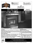
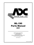
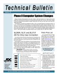
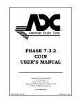
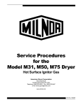
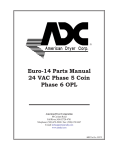
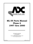
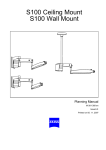
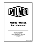
1
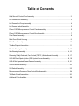
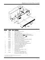
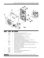
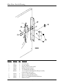
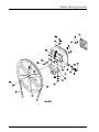
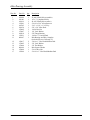
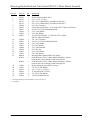
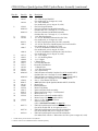
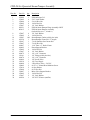
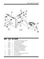
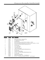
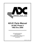
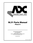
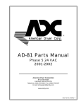
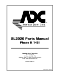
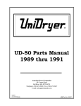
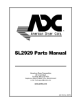
UD-80 Parts Manual 24 VAC Phase 5 1993/1994 American Dryer Corporation 88 Currant Road Fall River, MA 02720-4781 Telephone: (508) 678-9000 / Fax: (508) 678-9447 E-mail: [email protected] www.amdry.com ADC Part No. 450134 Retain This Manual In A Safe Place For Future Reference American Dryer Corporation products embody advanced concepts in engineering, design, and safety. If this product is properly maintained, it will provide many years of safe, efficient, and trouble-free operation. ONLY qualified technicians should service this equipment. OBSERVE ALL SAFETY PRECAUTIONS displayed on the equipment or specified in the installation/operator's manual included with the dryer. The following “FOR YOUR SAFETY” caution must be posted near the dryer in a prominent location. FOR YOUR SAFETY POUR VOTRE SÉCURITÉ Do not store or use gasoline or other flammable vapors and liquids in the vicinity of this or any other appliance. Ne pas entreposer ni utiliser d’essence ni d’autres vapeurs ou liquides inflammables à proximité de cet appareil ou de tout autre appareil. We have tried to make this manual as complete as possible and hope you will find it useful. The manufacturer reserves the right to make changes from time to time, without notice or obligation, in prices, specifications, colors, and material, and to change or discontinue models. The illustrations included in this manual may not depict your particular dryer exactly. IMPORTANT For your convenience, log the following information: UD-80 DATE OF PURCHASE __________________________________________________ MODEL NO. _________________ RESELLER’S NAME _______________________________________________________________________________ Serial Number(s) _________________________________________________________________________________ ________________________________________________________________________________________________ ________________________________________________________________________________________________ Replacement parts can be obtained from your reseller or the ADC factory. When ordering replacement parts from the factory, you can FAX your order to ADC at +1 (508) 678-9447 or telephone your order directly to the ADC Parts Department at +1 (508) 678-9000. Please specify the dryer model number and serial number in addition to the description and part number, so that your order is processed accurately and promptly. IMPORTANT NOTE TO PURCHASER Information must be obtained from your local gas supplier on the instructions to be followed if the user smells gas. These instructions must be posted in a prominent location near the dryer. Table of Contents High Security Control Door Assembly .................................................................................... 2 Lint Drawer/Door Assembly ................................................................................................... 3 Lint Drawer/Lint Coop Assembly ........................................................................................... 4 Lint Drawer Switch Assembly ................................................................................................ 5 Phase 5 OPL Microprocessor Control Panel Assembly ......................................................... 6 Phase 5 OPL Microprocessor Control Box Assembly ............................................................ 7 Front Panel Assembly ........................................................................................................... 8 Main Door Switch Housing .................................................................................................... 9 Main Door Assembly ........................................................................................................... 10 Tumbler/Support Assemblies ............................................................................................... 11 Tumbler Bearing Assembly ............................................................................................ 12, 13 Idler Bearing Assembly .................................................................................................. 14, 15 Reversing Totally Enclosed, Fan-Cooled (T.E.F.C.) Motor Mount Assembly .................... 16, 17 UDG-80 Direct Spark Ignition (DSI) Upshot Burner Assembly ........................................ 18, 19 UDS-80 Air Operated Steam Damper Assembly ........................................................... 20, 21 Sensor Bracket Assembly ................................................................................................... 22 Sail Switch Assembly .......................................................................................................... 23 Microprocessor Reversing Rear Control Box Assembly ....................................................... 24 Top/Back Guard Assemblies ............................................................................................... 25 Additional Parts Available ................................................................................................... 26 High Security Control Door Assembly Illus. No. Part No. Qty. 160017 160016 112312* 881053* 881052* 870011 800020** 1 1 1 1 1 1 1 800144 1 5 6 7 8 9 10 11 12 180202 102307 150201 150300 102600 102601 102502 122116 1 3 6 4 1 1 1 1 13 323635 1 14 150300 1 1 2 3 4 Description Special Dummy Lock ONLY Lock Cam ONLY UniDryer® Logo ONLY ADC Logo with Tape (for ALL Coin Models Only) Metal ADC Logo with Tape (for ALL OPL Models Only) Logo Double Tape Kit ONLY High Security Control Door Assembly (includes illus. nos. 4 through 7) Stainless Steel High Security Control Door Assembly (includes illus. nos. 4 through 7) Top Trim Strip with Lock Hole (38-1/4 length) Trim Bumper Gasket (sold by the foot) #10-32 x 1/4” Phillips Round Head Machine Screw #10 x 1/2” Hex Washer TEK Screw Control Door Rod Support Catch Control Door Rod Retainer Clip Control Door Support Rod Switch 24 VAC (for models mfd. as of May 5, 1993) Switch Box Cover (for models mfd. as of May 5, 1993) #16 x 1/2” Hex Washer TEK Screw (for models mfd. prior to May 5, 1993) * Logo tape kit is not included and must be ordered separately. ** Specify color when ordering. 2 American Dryer Corp. 450134-7 Lint Drawer/Door Assembly Illus. No. Part No. Qty. 1* 880826 1 2* 3 4 5 6 7 880840 150201 102307 180212 117604 150309 1 6 3 1 6 6 Description Lint Door Assembly (includes illus. nos. 1 and 3 through 5) Lint Drawer Assembly #10-32 x 1/4” Phillips TEK Screw Trim Bumper Gasket Mid Trim Kick Plate Neoprene Sponge Tape (sold by the foot) #10-16 x 1/2” Hex Head TEK Crimptite Screw * Specify color when ordering. 450134-7 www.amdry.com 3 Lint Drawer/Lint Coop Assembly Illus. No. 4 Part No. Qty. 1 2 3 4 5 6 7 8 9 881017 881018 881019 881020 115993 154200 881021 150300 323626 1 1 1 1 1 4 1 5 1 10 11 12 13 14 121405 881022 802163 150300 154200 1 1 1 5 4 Description Lint Back Cover Felt Stiffener Felt Retainer Wrapper Middle Support Lint Drawer Felt 5/32” Pop Rivet Right Side Lint Wall #10 x 1/2” Hex Washer TEK Screw Temperature Sensor Bracket ONLY (refer to Sensor Bracket Assembly on page 22) Large Rubber Grommet Only Middle Side Lint Wall Left Side Lint Wall #10 x 1/2” Hex Washer TEK Screw 5/32” Pop Rivet American Dryer Corp. 450134-7 Lint Drawer Switch Assembly Illus. No. 1 2 3 4 450134-7 Part No. 323635 122116 151001 121405 Qty. 1 1 2 1 Description Lint Drawer Switch Cover Lint Drawer Switch #8-32 Pal Nut Large Rubber Grommet www.amdry.com 5 Phase 5 OPL Microprocessor Control Panel Assembly Illus. No. 1 2 3 4 5 6 7 Part No. Qty. 112535 112276 112275 1 1 1 112277 1 112278 1 801255 801256 801207 1 1 1 824459 1 137231 824998 153010 150005 160005 136048 1 1 2 2 1 1 Description OPL English Keyboard Label Assembly OPL Stick-on Labels (English Only) ... Not Illustrated OPL Stick-on Labels (Spanish, Italian, and Hebrew) ... Not Illustrated 3-Language OPL Stick-on Labels (English, Spanish and Hebrew) ... Not Illustrated 5-Language OPL Stick-on Labels (Italian, Dutch, French, German and Chinese) ... Not Illustrated Phase 5 Microprocessor Control Panel ONLY Phase 5 Microprocessor Control Panel ONLY with Battery Bracket Phase 5 OPL Reversing Microprocessor Control Panel Assembly Complete (includes illus. nos. 1 through 6) Phase 5 OPL Reversing Microprocessor Control Panel Assembly with Battery Option Complete (includes illus. nos. 1 though 6) Phase 5 OPL Reversing Microprocessor Controller (computer) ONLY Phase 5 Battery Clip #6 Star Washer #6-32 x 1/4” Phillips Round Head Machine Screw Spring Turn Latch (2-piece) 1/8-Amp Fuse ONLY IMPORTANT: Check label on computer chip to verify correct part number for controller (computer). 6 American Dryer Corp. 450134-7 Phase 5 OPL Microprocessor Control Box Assembly Illus. No. 1 2 3 4 5 6 7 8 9 10 Part No. 141403 132023 150300 120715 150002 151000 136057 150301 136008 122641 122706 Qty. 1 1 2 1 2 2 * * * 1 * Description 24 VAC Transformer (for 60 Hz models Only) 24 VAC Transformer (for 50 Hz models Only) #10 x 1/2” Hex Washer TEK Screw 30-Position Terminal Block #6-32 x 1” Phillips Round Head Machine Screw #6-32 Pal Nut 1/2-Amp (Slo-Blo) Fuse ONLY #8-18 x 7/16” Phillips Pan Head TEK Screw Fuse Block and Strip Only 15-Pin Microprocessor Connector Mate-N-Lock Socket * As required. 450134-7 www.amdry.com 7 Front Panel Assembly Illus. No. 1 2 3 4 5 * 8 Part No. Qty. 880817 1 880816 1 154215 170330 150309 121405 2 1 9 1 Description Right Hand Insulated Front Panel Assembly Complete (includes illus. nos. 1, 2 and 3) Left Hand Insulated Front Panel Assembly Complete (includes illus. nos. 1, 2 and 3) 5/32” x 1/4” Pop Rivet Friction Door Latch #10-16 x 1/2” Hex Head TEK Crimptite Screw Rubber Grommet Specify color when ordering. American Dryer Corp. 450134-7 Main Door Switch Housing Illus. No. Part No. Qty. 1 2 3 4 5 6 152013 153008 137005 121028 154281 800448 2 2 1 2 2 1 7 8 9 10 153565 313218 150201 121405 2 1 2 1 450134-7 Description #6-32 Hex Nut #6 Lock Washer Singe-Pole Door Switch ONLY Insulated Female Terminal 3/8” Standard Nylon Spacer 12-1/2” Stainless Steel Main Door Hinge Assembly (includes illus. nos. 6 and 7) #6-32 x 1” Self Clinching Stud Main Door Switch Housing ONLY #10-32 x 1/4” Phillips Pan Head TEK Screw Rubber Grommet www.amdry.com 9 Main Door Assembly Illus. No. Qty. 1 881421 1 2 3 4 5 6 800448 150410 152014 102353 102212 170730 150448 170319 150431 4 4 1 1 1 1 4 4 1 7 8 9 10 Part No. Description Gray Plastic Main Door Assembly Complete with Mechanical Fasteners (includes illus. nos. 1 and 5 through 9) 12-1/2” Stainless Steel Main Door Hinge Assembly #10-24 x 3/8” Phillips Pan Head Taptite Screw 1/4-20 Free Spin Wash Nut Main Door Gasket 20-7/16” Door Glass with (4) Holes Main Door Glass Adhesive (10.3 oz. cartridge) 1/2” Stainless Steel Flat Head Allen Screw Door Glass (Nylon) Spacer Main Door Latch Screw (#10 x 7/16” Dome Hex Head) American Dryer Corp. 450134-7 Tumbler/Support Assemblies Illus. No. 1 2 3 4 5 6 7 8 9 10 11 -- Part No. Qty. 880818* 1 880827 1 154210 301308 150500 100905 153004 800615 152005 153005 153004 116000 401010 40 4 1 4 4 1 4 4 4 1 1 Description Tumbler ONLY without Felt Collar (includes illus. nos. 1, 2, and 3) Reversing Tumbler and Support Assembly Complete (includes illus. nos. 1 through 11) 5/32” x 3/16” Pop Rivet Tumbler Rib ONLY 5/16-18 x 3/4” Socket Button Head Screw 3/8-16 x 37 Tie Rod 3/8” Flat Washer Reversing Tumbler Support ONLY 3/8” Hex Nut 3/8” Lock Washer 3/8” Flat Washer Felt Collar ONLY #847 Adhesive (5 oz. tube) * Felt collar is not included and must be ordered separately. 450134-7 www.amdry.com 11 Tumbler Bearing Assembly 12 American Dryer Corp. 450134-7 Tumbler Bearing Assembly Illus. No. 1 2 3 4 5 6 7 8 9 10 11 12 13 14 15 16 17 18 19 20 21 22 23 24 25 26 Part No. Qty. 880220 153025 152050 150508 153005 152005 150600 153004 153005 152005 150501 153002 153001 150621 152004 801101 1 4 4 2 2 2 2 * 2 2 4 4 4 2 2 1 801103 1 801105 801104 880779 1 1 1 880202 1 152004 150610 101118 101119 154301 100735 100106 824807 2 2 1 1 2 1 1 1 Description 1-3/4” Flange Bearing ONLY 9/16” Lock Washer 9/16-12 Hex Nut 3/8-16 x 3/4” Hex Head Machine Bolt 3/8” Lock Washer 3/8-16 Hex Nut 3/8-16 x 1-1/2” Hex Head Machine Bolt 3/8” Flat Washer 3/8” Lock Washer 3/8-16 Hex Nut 5/16-18 x 3/4” Hex Head Machine Bolt 5/16” Lock Washer 5/16” Flat Washer 5/16-18 x 1-1/2” Hex Head Machine Bolt 5/16-18 Hex Nut 1-3/8” Bearing Box Assembly Complete (includes illus. nos. 4 through 20) For models without Rotation Sensor Option 1-3/8” Bearing Box and Support ONLY (includes illus. nos. 4, 5, 6, 16, and 17) 1-3/8” Bearing Box ONLY Pillow Block Bearing Support ONLY 1-3/8” Pillow Block Bearing Assembly with Magnet (for models mfd. as of April 5, 1993) 1-3/8” Pillow Block Bearing ONLY (for models mfd. as of April 5, 1993) 5/16-18 Hex Nut 5/16-18 x 1-1/2” Allen Setscrew 18-3/4” Pulley 1-3/8” Taper Lock Hub (key not included) 5/16-18 x 5/16” Allen Setscrew Shaft Key (for taper lock hub) 5L-690 V-Belt (to idler assembly) Rotational Sensor Assembly (for models mfd. as of April 5, 1993) * As required. 450134-7 www.amdry.com 13 Idler Bearing Assembly 14 American Dryer Corp. 450134-7 Idler Bearing Assembly Illus. No. Part No. Qty. 1 2 3 4 5 6 7 8 9 10 11 100106 101140 100114 154301 100705 301850 152002 153007 100214 150521 801007 1 1 1 2 1 1 3 3 2 3 1 12 13 14 15 16 17 150617 153005 153004 801009 152004 150509 2 2 2 1 1 1 450134-7 Description 5L-690 V-Belt (idler to tumbler) 14” x 3” Compound Pulley 4L-630 V-Belt (idler to motor) 5/16-18 x 5/16” Allen Setscrew 3/16” x 3/16” x 1-3/8” Key 5/8” x 3/4” Idler Shaft 1/4-20 Hex Nut 1/4” Lock Washer 5/8” Flange Bearing 1/4-20 x 2” Carriage Bolt Idler Bearing Assembly Complete (includes illus. nos. 5 through 17) 3/8-16 x 1” Hex Head Machine Bolt 3/8” Lock Washer 3/8” Flat Washer Idler Square Washer 5/16-18 Hex Nut 5/16-18 x 3” Hex Head Machine Bolt www.amdry.com 15 Reversing Totally Enclosed, Fan-Cooled (T.E.F.C.) Motor Mount Assembly 16 American Dryer Corp. 450134-7 Reversing Totally Enclosed, Fan-Cooled (T.E.F.C.) Motor Mount Assembly Illus. No. 1 2 3 4 5 6 7 8 9* 10 11 12 13 14 15 16 17 18 19 20 21 22 23 24 Part No. Qty. 100114 100701 101130 101139 120200 181003 150501 153002 153001 100023 1 1 1 1 1 1 4 4 4 1 120200 150501 153002 153001 154000 152004 153002 153001 800920 803959 1 4 4 4 8 7 7 7 1 1 803964 1 117604 153051 100705 100605 153050 152006 5 1 1 1 ** 2 Description 4L-630 V-Belt (motor to idler) 3/16” x 3/16” x 1” Key 5/8” x 2-1/2” Motor Pulley (for 60 Hz models Only) 5/8” x 2-3/4” Motor Pulley (for 50 Hz models Only) 3/8” x 90° Connector 1/2 hp 208/230/380/460v 3ø 50/60 Hz T.E.F.C. Motor (56Z frame) 5/16-18 x 3/4” Hex Head Machine Bolt 5/16” Lock Washer 5/16” Flat Washer 3 hp 220/230/380/460v 3ø 50/60 Hz T.E.F.C. Motor with 3/4” Shaft (56Z frame) 3/8” x 90° Connector 5/16-18 x 3/4” Hex Head Machine Bolt 5/16” Lock Washer 5/16” Flat Washer 5/16” Tinnerman Nut 5/16” Hex Nut 5/16” Lock Washer 5/16” Flat Washer Reversing Motor Mount ONLY (56Z frame) 60 Hz Reversing T.E.F.C. Motor Mount Assembly Complete (includes illus. nos. 2 through 14 and 18 through 24) 50 Hz Reversing T.E.F.C. Motor Mount Assembly Complete (includes illus. nos. 2 through 14 and 18 through 24) Neoprene Sponge Tape (sold by the foot) 3/4” S.A.E. Flat Washer 3/16” x 3/16” x 1-3/8” Key 13” Impellor with 5/8” Bore 1/2” S.A.E. Flat Washer 1/2-20 Left Hand Jam Nut * Check part number on motor data label to verify correct motor. ** As required. 450134-7 www.amdry.com 17 UDG-80 Direct Spark Ignition (DSI) Upshot Burner Assembly Illus. No. 1 2 3 4 5 6 18 Part No. Qty. 150300 130401 323643 323641 323644 140838* 19 1 1 1 1 2 140840* 2 140819* 2 140821* 2 140840* 2 140821* 2 140832* 1 140834* 1 140819* 1 140818* 1 Description #10 x 1/2” Hex Washer TEK Screw 330° Hi-Limit Thermostat ONLY Oven Top Cover Burner Front Oven Inlet Cover #3 (Natural Gas) Burner Orifice (for 60 Hz models mfd. as of August 20, 1992) #1 (Natural Gas) Burner Orifice (for 60 Hz models mfd. prior to August 20, 1992) #30 (Liquid Propane Gas) Burner Orifice (for 60 Hz models mfd. as of April 1, 1993) #28 (Liquid Propane Gas) Burner Orifice (for 60 Hz models mfd. prior to April 1, 1993) #1 (Natural Gas) Burner Orifice (for 50/60 Hz models mfd. as of August 20, 1992) #28 (Liquid Propane Gas) Burner Orifice (for 50/60 Hz models mfd. as of August 20, 1992) #4 (Natural Gas) Burner Orifice (for 50 Hz models mfd. as of August 20, 1992) #5 (Natural Gas) Burner Orifice (for 50 Hz models mfd. as of August 20, 1992) #30 (Liquid Propane Gas) Burner Orifice (for 50 Hz models mfd. as of August 20, 1992) #31 (Liquid Propane Gas) Burner Orifice (for 50 Hz models mfd. as of August 20, 1992) American Dryer Corp. 450134-7 UDG-80 Direct Spark Ignition (DSI) Upshot Burner Assembly (continued) Illus. No. 7 Part No. Qty. 141247 1 141246 1 323642 880822** 1 1 880823** 1 332119 128928 1 1 881052 140411 1 1 140017 1 140018 1 142715 142923 142808 142602 318317 319712 141302 331291 121492 880824** 1 1 2 1 1 1 1 1 2 1 880824** 1 27 28 150299 880815 141110 323600 323598 128915 305412 323599 323594 29 30 150300 --------- 4 1 2 1 1 1 1 1 1 2 6 – --- 880777* 1 --- 880778* 1 --- 880763* 1 8 9 10 11 12 13 14 15 16 17 18 19 20 21 22 23 24 25 26 Description 1/2” 2-Port Swage Manifold (for models mfd. as of August 20, 1992) 1/2” 2-Port Manifold (for models mfd. prior to August 20, 1992) Gas Valve Support Bracket Gas Valve (Natural Gas) Manifold Assembly (includes illus. nos. 7 through 15, 17, 18 and 29) Gas Valve (Natural Gas) Manifold Assembly (includes illus. nos. 7 through 15, 17, 18 and 29) 1-3/8” Hole Pipe Bracket 1/2” 24 VAC Redundant (Natural Gas) Gas Valve (for models mfd. as of August 20, 1992) 1/2” DSI (Liquid Propane Gas) Gas Valve Assembly 1/2” 24 VAC Gas Valve (Liquid Propane Gas) Conversion Kit (for models mfd. as of August 20, 1992) 1” 24 VAC Redundant (Natural Gas) Gas Valve (for models mfd. prior to August 20, 1992) 1” 24 VAC Redundant (Liquid Propane Gas) Gas Valve (for models mfd. prior to August 20, 1992) 1/2” x 1/2” Nipple 1” x 1/2” Reducing Elbow 1” x 3” Nipple 1” Black Union 7/8” Hole Pipe Bracket Burner Hi-Limit Bracket 1” Shutoff Valve 1-1/8” Hole Pipe Bracket 3/16” Nylon Clamp UDG-80 Burner Assembly Complete (for 60 Hz models ONLY) (includes illus. nos. 1 through 4, 16 and 23 through 28) UDG-80 Burner Assembly Complete (for 50 Hz models ONLY) (includes illus. nos. 1 through 4, 16 and 23 through 28) #10 x 1” Hex Washer TEK Screw ADC DSI (Direct Spark Ignition) Module ONLY (50/60 Hz) Burner Tube Manifold Retainer Burner Tube Holder Ignitor and Flame-Probe Assembly Ignitor Gap Feeler Gauge ... Not Illustrated Burner Side Cover Burner Louver (for 60 Hz models ONLY) Burner Louver (for 50 Hz models ONLY) #10 x 1/2” Hex Washer TEK Screw Sail Switch Assembly (refer to Sail Switch Assembly on page 23) UDG-80 Liquid Propane Conversion Kit with Orifices (for 60 Hz models mfd. as of August 20, 1992) UDG-80 Liquid Propane Conversion Kit with Orifices (for 50 Hz models mfd. prior to August 20, 1992) UDG-80 Liquid Propane Conversion Kit with Orifice (for models mfd. with the 1” Robershaw Gas Valve prior to August 20, 1992) * Consult factory for elevations over 2,000 feet. ** Burner orifice is not included and must be ordered separately. 450134-7 www.amdry.com 19 UDS-80 Air Operated Steam Damper Assembly 20 American Dryer Corp. 450134-7 UDS-80 Air Operated Steam Damper Assembly Illus. No. Part No. Qty. 1 2 3 4 5 6 7 165009 153002 152004 152002 153007 820321 803415 1 6 6 4 4 2 1 8 9 10 11 12 13 14 15 16 17 18 19 20 21 22 23 24 25 26 27 28 29 30 153007 152002 115995 102350 151007 152007 100497 100492 152002 153007 100472 143110 100470 100496 143238 100498 150002 153010 152000 330987 152002 153007 100520 4 4 108 1 1 1 1 1 4 4 1 1 1 1 1 1 2 2 1 1 2 2 1 450134-7 Description UDS-80 Steam Coil 5/16” Lock Washer 5/16-18 Hex Nut 1/4-20 Hex Nut 1/4” Lock Washer UDS-80 Steam Damper Hinge Assembly ONLY UDS-80 Steam Damper Assembly (includes illus. nos. 7, 10 and 11) 1/4” Lock Washer 1/4-20 Hex Nut Steam Damper Gasket (sold by the inch) Steam Damper Foam (68-1/2” length) 7/16-20 Stainless Steel Acorn Nut 7/16-20 Hex Nut 1-1/4” Bore x 3” Stroke Piston Piston Support Bracket 1/4-20 Hex Nut 1/4” Lock Washer 1/4” x 1/8” Connector 1/4” Tubing (sold by the foot) 1/4” x 1/8” Connector 1/8” Needle Valve 1/8” Close Nipple 3-Way Micro Valve – 24 VAC #6-32 x 1” Slotted Head Machine Screw #6 Star Washer #6-32 Hex Nut Micro Valve Support Bracket 1/4-20 Hex Nut 1/4” Lock Washer 1/8” N.P.T. Silencer (muffler) www.amdry.com 21 Sensor Bracket Assembly Illus. No. 22 Part No. Qty. 1 880251 1 2 3 4 5 6 122605 122701 122801 154007 150000 802174 1 4 1 2 2 1 7 8 9 10 11 12 323626 130103 153010 152000 150301 122604 122700 1 1 2 2 2 1 4 Description 1/4” Temperature Sensor Probe Assembly (includes illus. nos. 1 through 4) 4-Pin Socket Connector ONLY Socket Terminal ONLY Pin/Socket Extraction Tool 1/4” Tinnerman Push-on Fastener #6-32 x 1/4” Right Hand Machine Screw Sensor Bracket Assembly Complete (includes illus. nos. 1 through 9) Temperature Sensor Bracket ONLY 225° Large Automatic Thermostat #6 Star Washer #6-32 Hex Nut #8-18 x 7/16” Phillips Pan Head TEK Screw 4-Pin Connector ONLY Pin Terminal ONLY American Dryer Corp. 450134-7 Sail Switch Assembly Illus. No. Part No. Qty. 1 2 3 4 105500 319202 154002 802800 802801 1 1 1 1 1 5 6 7 8 9 10 150300 150303 122200 802799 150309 154004 2 2 1 1 2 1 450134-7 Description Sail Switch Actuator Rod Sail Switch Damper (flat) 1/8” Push-On Fastener Sail Switch Box with Cover and Bracket ONLY Sail Switch Box Assembly Complete (includes illus. nos. 1 through 4 and 6 through 10) #10 x 1/2” Hex Washer TEK Screw #4 x 3/4” Pan Head “A” Machine Screw Sail Switch ONLY Sail Switch Box Cover and Bracket ONLY #10-16 x 1/4” Hex Head TEK Crimptite Screw Twin Speed Nut www.amdry.com 23 Microprocessor Reversing Rear Control Box Assembly Illus. No. 1 2 3 4 5 6 7 8 9 10 11 12 13 14 15 ----24 Part No. 322812 137060 137013 132431 132432 150103 151001 153002 152004 132445 150103 151001 120701 150008 151000 121300 322809 150301 Qty. 1 1 2 1 1 2 2 1 1 1 2 2 1 2 2 3 1 4 Description Back Electrical Box Component Plate Arc Suppressor Board ONLY Nylon Standoff Reversing Contactor (208/230/240v, 50/60 Hz) – 24 VAC Reversing Contactor Replacement Coil (208/230/240v, 50/60 Hz) – 24 VAC #8-32 x 3/4” Phillips Round Head Machine Screw #8-32 Pal Nut 5/16” Lock Washer 5/16-18 Hex Nut 3 hp Contactor ONLY #8-32 x 3/4” Phillips Round Head Machine Screw #8-32 Pal Nut 4-Position Terminal Block #6-32 x 1-1/4” Slotted Round Head Machine Screw #6-32 Pal Nut Open and Close Bushing Black Electrical Box Cover ... Not Illustrated #8-18 x 7/16” Phillips Pan Head TEK Screw ... Not Illustrated American Dryer Corp. 450134-7 Top/Back Guard Assemblies Illus. No. 1 2 3 4 5 6 7 8 9 10 11 450134-7 Part No. 312527 150301 314510 150301 322809 150301 314511 150301 103500 880939 104005 112519 Qty. 1 8 1 8 1 8 1 8 4 1 1 1 Description Outer Top Assembly (for Gas Models Only) #8-18 x 7/16” Phillips Pan Head TEK Screw Top Back Guard #8-18 x 7/16” Phillips Pan Head TEK Screw Rear Electrical Box Cover #8-18 x 7/16” Phillips Pan Head TEK Screw Lower Back Guard #8-18 x 7/16” Phillips Pan Head TEK Screw Adjustable Leveling Leg 10” Damper Assembly (for Gas Models Only) 12” Damper Assembly (for Steam Models Only) “Routine Maintenance Schedule” Label ONLY www.amdry.com 25 Additional Parts Available Part No. 112039 112280 112534 114001 114006 120802 120902 120903 121006 121014 121026 121499 121500 121503 122804 404500 404502 404506 404507 880200 26 Description “Black/White/Green Ground” Label “Clean Lint Screen” Label “Phase 5 OPL Program Location Summary” Label “CAUTION – Exhausted/Lint Screen” Label “WARNING – Fire Hazards” Label Red Butt Connector #74B Wire Nut Crimp-on Wire Nut #10 Insulated Ring Terminal 1/4” Insulated (female) Terminal Tab Receptacle Combination 5-1/2” Harness Tie 8” Harness Tie Harness Tie Mounting Clip Manometer (Hydro Gauge) for measuring Gas Pressure Almond Brush-In-Cap Bottle Touch-Up Paint White-Brush-In-Cap Bottle Touch-Up Beige Brush-In-Cap Bottle Touch-Up Paint Cornflower Blue Brush-In-Cap Bottle Touch-Up Paint Electrical Terminal (assortment) Kit American Dryer Corp. 450134-7 Notes 450134-7 www.amdry.com 27 ADC Part No. 450134 7 - 12/27/05 - 0