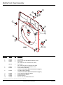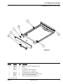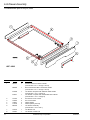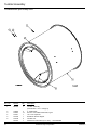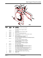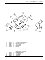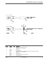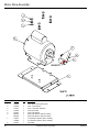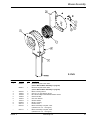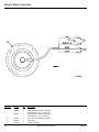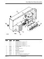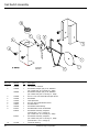
1
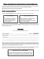
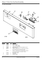
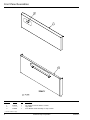
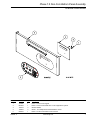
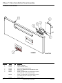
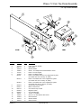
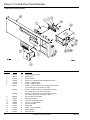
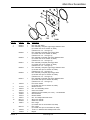
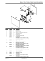
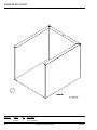
SL20 Gen II
Parts Manual
Phase 7
American Dryer Corporation
88 Currant Road
Fall River, MA 02720-4781
Telephone: (508) 678-9000 / Fax: (508) 678-9447
E-mail: [email protected]
www.amdry.com
ADC Part No. 450599 - 2
Retain This Manual In A Safe Place For Future Reference
American Dryer Corporation products embody advanced concepts in engineering, design, and safety. If this product
is properly maintained, it will provide many years of safe, efficient, and trouble free operation.
ONLY qualified technicians should service this equipment.
OBSERVE ALL SAFETY PRECAUTIONS displayed on the equipment or specified in the installation manual included
with the dryer.
The following “FOR YOUR SAFETY” caution must be posted near the dryer in a prominent location.
FOR YOUR SAFETY
POUR VOTRE SÉCURITÉ
Do not store or use gasoline or
other flammable vapors and
liquids in the vicinity of this or
any other appliance.
Ne pas entreposer ni utiliser d’essence
ni d’autres vapeurs ou liquides
inflammables à proximité de cet appareil
ou de tout autre appareil.
We have tried to make this manual as complete as possible and hope you will find it useful. ADC reserves the right to
make changes from time to time, without notice or obligation, in prices, specifications, colors, and material, and to
change or discontinue models.
Important
For your convenience, log the following information:
DATE OF PURCHASE ____________________________________________________
SL20 PH7
MODEL NO. ______________
RESELLER’S NAME _________________________________________________________________________________
Serial Number(s) _____________________________________________________________________________________
____________________________________________________________________________________________________
____________________________________________________________________________________________________
Replacement parts can be obtained from your reseller or the ADC factory. When ordering replacement parts from the
factory, you can FAX your order to ADC at (508) 678-9447 or telephone your order directly to the ADC Parts Department
at (508) 678-9000. Please specify the dryer model number and serial number in addition to the description and part
number, so that your order is processed accurately and promptly.
The illustrations on the following pages may not depict your particular dryer exactly. The illustrations are a composite
of the various dryer models. Be sure to check the descriptions of the parts thoroughly before ordering.
“IMPORTANT NOTE TO PURCHASER”
Information must be obtained from your local gas supplier on the
instructions to be followed if the user smells gas. These
instructions must be posted in a prominent location near the dryer.
Table of Contents
Phase 7.3 Non-Coin Top Panel Assembly for Top Control Models ............................................................................... 4
Phase 7.5 Non-Coin Top Panel Assembly for Top Control Models ............................................................................... 5
Front Panel Assemblies .............................................................................................................................................. 6
Phase 7.5 Non-Coin Bottom Panel Assembly for Bottom Control Models ................................................................... 7
Phase 7.3 Non-Coin Bottom Panel Assembly for Bottom Control Models ................................................................... 8
Phase 7.3 Coin Top Panel Assembly for Top Control Models ...................................................................................... 9
Phase 7.3 Coin Bottom Panel Assembly for Bottom Control Models ........................................................................ 10
Main Door Assemblies .............................................................................................................................................. 11
Middle Front Panel Assembly ................................................................................................................................... 12
Lint Drawer Assembly for Models Mfd. as of July 29, 2005 ....................................................................................... 13
Lint Drawer Assembly for Models Mfd. prior to July 29, 2005 .................................................................................... 14
Tumbler Assembly for Models Mfd. as of May 2004 .................................................................................................. 15
Tumbler Assembly for Models Mfd. prior to May 2004 ............................................................................................... 16
Rear Support Panel Assembly .................................................................................................................................. 17
Front Tumbler Wheel Assemblies ............................................................................................................................. 18
Rear Tumbler Wheel Assemblies .............................................................................................................................. 19
Fire Suppression System Piping Assembly .............................................................................................................. 20
Temperature Sensor Assemblies ............................................................................................................................... 21
Motor Drive Assembly ............................................................................................................................................... 22
Direct Spark Ignition Burner Assembly ...................................................................................................................... 24
Lint Box / Blower Motor Assembly ............................................................................................................................ 26
Electric Oven Assembly ............................................................................................................................................ 28
Blower Assembly ...................................................................................................................................................... 29
Blower Motor Assembly ............................................................................................................................................ 30
Front Electrical Panel Assembly ............................................................................................................................... 31
Sail Switch Assembly ............................................................................................................................................... 32
Base / Top / Sides / Back Guard Assemblies ........................................................................................................... 33
Pedestal Box Option ................................................................................................................................................. 34
Additional Parts Available ......................................................................................................................................... 35
Phase 7.3 Non-Coin Top Panel Assembly
For Top Control Models
Illus. No.
Part No.
Qty.
1
2
3
4
5
6
112579
137250
137270
150005
153010
887012
1
1
1
4
4
1
887009
1
818482
––––––*
818206
1
1
1
7
8
9
Description
Phase 7 Keypad
Phase 7 Ribbon Cable
Large Character Display
#6-32 x 1/4” Phillips Round Head Machine Screw
#6 Star Washer
Phase 7.3.2 Board with a Fire Suppression System
(for models mfd. as of January 22, 2004)
Phase 7.3.2 Board with a Fire Suppression System
(for models mfd. prior to January 22, 2004)
Black Control Panel
Logo ONLY
Magnetic Switch
* Contact reseller for logo.
4
American Dryer Corporation
450599 - 2
Phase 7.5 Non-Coin Top Panel Assembly
For Top Control Models
Illus. No.
Part No.
Qty.
1
2
3
4
5
6
112580
153010
150005
887020
818463
818206
1
3
3
1
1
1
450599 - 2
Description
Phase 7.5 Non-Coin Keypad
#6 Star Washer
#6-32 x 1/4” Phillips Round Head Machine Screw
Phase 7.5 Non-Coin Board with a Fire Suppression System
Non-Coin Top Control Panel
Magnetic Switch
www.amdry.com
5
Front Panel Assemblies
Illus. No.
Part No.
Qty.
1
2
3
818478
––––––*
818466
1
–
1
Description
Top Control Panel for Bottom Controls
Logo ONLY
Front Bottom Panel Assembly for Top Controls
* Contact reseller for logo.
6
American Dryer Corporation
450599 - 2
Phase 7.5 Non-Coin Bottom Panel Assembly
For Bottom Control Models
Illus. No.
Part No.
Qty.
1
2
3
4
5
112580
887020
153010
150005
818465
1
1
3
3
1
450599 - 2
Description
Phase 7.5 Non-Coin Keypad
Phase 7.5 Non-Coin Board with a Fire Suppression System
#6 Star Washer
#6-32 x 1/4” Phillips Round Head Machine Screw
Phase 7.5 Non-Coin Bottom Control Panel
www.amdry.com
7
Phase 7.3 Non-Coin Bottom Panel Assembly
For Bottom Control Models
Illus. No.
Part No.
Qty.
1
2
3
4
5
6
112579
137270
818436
150005
153010
887012
1
1
1
4
4
1
887009
1
137250
1
7
8
Description
Phase 7.3 Keypad
Large Character Display
Non-Coin Bottom Control Panel
#6-32 x 1/4” Phillips Round Head Machine Screw
#6 Star Washer
Phase 7.3.2 Board with a Fire Suppression System
(for models mfd. as of January 22, 2004)
Phase 7.3.2 Board with a Fire Suppression System
(for models mfd. prior to January 22, 2004)
Ribbon Cable
American Dryer Corporation
450599 - 2
Phase 7.3 Coin Top Panel Assembly
For Top Control Models
Illus. No.
Part No.
Qty.
1
2
3
4
5
6
7
137270
883774
153010
150005
112579
137250
887011
1
1
4
4
1
1
1
887012
1
887009
1
884029
818467
818132
818206
818500
150511
150300
153000
153012
152015
1
1
1
1
1
1
4
8
8
8
8
9
10
11
12
13
14
15
16
17
450599 - 2
Description
Large Character Display
Optic Switch
#6 Star Washer
#6-32 x 1/4” Phillips Round Head Machine Screw
Phase 7.3 Coin Keypad
Phase 7.3 Ribbon Cable
Phase 7.3.2 Board without a Fire Suppression System
(for models mfd. as of January 22, 2004)
Phase 7.3.2 Board with a Fire Suppression System
(for models mfd. as of January 22, 2004)
Phase 7.3.2 Board with a Fire Suppression System
(for models mfd. prior to January 22, 2004)
25¢ US Optic Coin Acceptor
Black Control Panel
Coin Vault for Top Control
Magnetic Switch
Coin Vault Bracket
1/4-20 x 1” Tap Bolt
#10-16 x 1/2” Hex Washer TEK Screw
#8 Flat Washer
#8 Star Washer
#8-32 Hex Nut
www.amdry.com
9
Phase 7.3 Coin Bottom Panel Assembly
For Bottom Control Models
Illus. No.
Part No.
Qty.
1
2
3
4
5
6
7
137270
883774
153010
150005
112579
137250
887011
1
1
4
4
1
1
1
887012
1
887009
1
884029
818424
818422
153049
153024
152015
153049
153012
152015
1
1
1
2
2
2
2
8
8
8
9
10
11
12
13
14
15
16
10
Description
Large Character Display
Optic Switch
#6 Star Washer
#6-32 x 1/4” Phillips Round Head Machine Screw
Phase 7.3 Coin Keypad
Phase 7.3 Ribbon Cable
Phase 7.3.2 Board without a Fire Suppression System
(for models mfd. as of January 22, 2004)
Phase 7.3.2 Board with a Fire Suppression System
(for models mfd. as of January 22, 2004)
Phase 7.3.2 Board with a Fire Suppression System
(for models mfd. prior to January 22, 2004)
25¢ US Optic Coin Acceptor
Black Control Panel
Coin Vault for Bottom Control
13/64” x 7/8” Flat Washer
#10 Lock Washer
#8 Hex Nut
13/64” x 7/8” Flat Washer
#8 Star Washer
#8-32 Hex Nut
American Dryer Corporation
450599 - 2
Main Door Assemblies
Illus. No.
Part No.
Qty.
1
2
883824
818832
1
1
818830
1
818833
1
818831
1
818562
1
818689
1
818561
1
3
102348
1
4
5
6
151016
150322
102314
401010
153000
153012
150327
887175
819838
103067
4
8
1
1
4
4
2
1
1
2
884134
2
150328
170608
2
1
7
8
9
10
11
12
13
450599 - 2
Description
Door Pan with Glass
Door Assembly Complete (right hinge) Stainless Steel
(for models mfd. as of October 25, 2004)
(includes illus. nos. 1 through 13)
Door Assembly Complete (right hinge) White
(for models mfd. as of October 25, 2004)
(includes illus. nos. 1 through 13)
Door Assembly Complete (left hinge) Stainless Steel
(for models mfd. as of October 25, 2004)
(includes illus. nos. 1 through 13)
Door Assembly Complete (left hinge) White
(for models mfd. as of October 25, 2004)
(includes illus. nos. 1 through 13)
Door Assembly Complete (right hinge) Stainless Steel
(for models mfd. prior to October 25, 2004)
(includes illus. nos. 1 through 13)
Door Assembly Complete (right hinge) White
(for models mfd. prior to October 25, 2004)
(includes illus. nos. 1 through 13)
Door Assembly Complete (left hinge) Stainless Steel
(for models mfd. prior to October 25, 2004)
(includes illus. nos. 1 through 13)
Inner Door Gasket
(for models mfd. prior to October 25, 2004)
#8-32 Acorn Nut
#6 x 1/2” Self-Drilling Screw
Outer Door Gasket
Adhesive for Door Gasket (5 oz. tube) … Not Illustrated
#8 Flat Washer
#8 Star Washer
#6 x 1/2” Phillips Flat Head Screw
Silver Door Handle
White Door Handle
Door Hinge
(for models mfd. as of November 20, 2003)
Door Hinge
(for models mfd. prior to November 20, 2003)
1/4-20 x 1” Stainless Steel Phillips Head Screw
Magnet
www.amdry.com
11
Middle Front Panel Assembly
Illus. No.
Part No.
Qty.
1
2
3
102004
152224
103067
4
4
2
884134
2
4
5
150321
818184
4
1
6
818183
1
7*
8
9
10
818609
318234
818206
150300
2
1
1
2
Description
Door Magnet
#10-32 x 1/2” Flat Head Spanner Machine Screw
Door Hinge
(for models mfd. as of November 20, 2003)
Door Hinge
(for models mfd. prior to November 20, 2003)
#10-32 x 1/2” Phillips Head Machine Screw
Front Left Wheel Assembly
(refer to Front Tumbler Wheel Assemblies on page 18)
Front Right Wheel Assembly
(refer to Front Tumbler Wheel Assemblies on page 18)
Front Felt Pad with Mounting Rivets
Rotational Sensor Bracket
Rotational Sensor
#10-16 x 1/2” Hex Washer TEK Screw
* Complete kit of front and rear pads with instructions (P/N 884172).
12
American Dryer Corporation
450599 - 2
Lint Drawer Assembly
For Models Mfd. as of July 29, 2005
Illus. No.
Part No.
Qty.
1
2
3
183129
170168
818801
819345*
2
1
1
1
4
5
6
7
819344*
819287
185226
150334
1
2
1
2
Description
#10-32 x 1/2” TORX® Head Machine Screw
Brush
Lint Drawer
Lint Drawer Assembly Complete
(includes illus. nos. 1 through 7)
Cold Rolled Steel Lint Drawer Handle
Lint Drawer Handle Fastening Plate Assembly
Black Lint Screen Handle Molded
#8-16 x 9/32” Phillips Pan Head Screw
* Specify color when ordering.
450599 - 2
www.amdry.com
13
Lint Drawer Assembly
For Models Mfd. prior to July 29, 2005
Illus. No.
Part No.
Qty.
1
883751
1
883859
1
818166
1
818471
1
2
3
4
5
6
151010
153024
318541
117605
883752
2
2
2
2
1
7
8
116054
102347
1
1
14
Description
Stainless Steel Lint Drawer Handle
(includes illus. nos. 1 through 5 and 8)
Black Cold Rolled Steel Lint Drawer Handle
(includes illus. nos. 1 through 5 and 8)
Lint Drawer Complete with Stainless Steel Handle
(includes illus. nos. 1 through 8)
Lint Drawer Complete with Cold Rolled Steel Handle
(includes illus. nos. 1 through 8)
#10-32 Hex Acorn Locknut
#10 Lock Washer
Offset Washer
Gasket (sold by the foot)
Lint Drawer Assembly
(includes illus. nos. 6 and 7)
Lint Drawer Felt
Lint Drawer Handle Pad
American Dryer Corporation
450599 - 2
Tumbler Assembly
For Models Mfd. as of May 2004
Illus. No.
Part No.
Qty.
1
115906
401010
102004
884363
154217
150123
318784
153048
185426
153072
150445
2
1
1
1
1
3
1
2
1
2
2
2
3
4
5
6
7
8
9
10
450599 - 2
Description
Tumbler Felt
Adhesive for Felt Collar (5 oz. tube) … Not Illustrated
Rotational Sensor Magnet
Tumbler Assembly Complete
1/8” x 1/2” Pop Rivet
1/4-20 x 1/4” Socket Button Head Cap Screw
Tumbler Shaft
Friction Pad
Dual Screw Backup Washer
Lock Washer
1/4-20 x 3/4” Socket Head Cap Screw
www.amdry.com
15
Tumbler Assembly
For Models Mfd. prior to May 2004
Illus. No.
Part No.
Qty.
1
884359
1
2
3
4
5
6
318242
150313
154217
102102
115906
401010
3
12
1
1
2
1
16
Description
Tumbler Assembly
(includes illus. nos. 1 through 6)
5” Tapered Rib
#10-16 x 1/2” TORX PLUS® BTN, Type 1
1/8” x 1/2” Pop Rivet
Rotational Sensor Magnet
Tumbler Felt
Adhesive for Felt Collar (5 oz. tube) … Not Illustrated
American Dryer Corporation
450599 - 2
Rear Support Panel Assembly
Illus. No.
Part No.
Qty.
1*
2
818608
318695
2
1
318628
1
3
4
5
6
7
8
318629
150300
318691
153073
150301
818487
1
16
1
15
2
1
9
818570
1
818114
1
10
11
818489
818109
1
1
12
818110
1
13
818228
1
14
120716
120728
151001
121010
1
1
2
2
15
16
Description
Rear Felt Pad with Shims and Pop Rivets
Junction Box
(for models mfd. as of August 21, 2003)
Junction Box
(for models mfd. prior to August 21, 2003)
Electric Cover
#10-16 x 1/2” Hex Washer TEK Screw
Cover Plate (for dryers without a fire suppression system)
#8-32 KEPS Nut
#8-18 x 7/16” Phillips Pan Head TEK Screw
Fire Suppression System Assembly
(refer to Fire Suppression System Piping Assembly on page 20)
Sail Switch Assembly
(for models mfd. as of January 23, 2004)
(refer to Sail Switch Assembly on page 32)
Sail Switch Assembly
(for models mfd. prior to January 23, 2004)
(refer to Sail Switch Assembly on page 32)
Heat Duct Assembly
Rear Right Wheel Assembly
(refer to Rear Tumbler Wheel Assemblies on page 19)
Rear Left Wheel Assembly
(refer to Rear Tumbler Wheel Assemblies on page 19)
Fire Suppression System Temperature Sensor
(refer to Temperature Sensor Assemblies on page 21)
2-Position Terminal Block (gas models Only)
4-Position Terminal Block (electric models Only)
#8-32 Pal Nut
Ground Lug
* Complete kit of front and rear pads with instructions (P/N 884172).
450599 - 2
www.amdry.com
17
Front Tumbler Wheel Assemblies
Illus. No.
Part No.
Qty.
1
2
3
4
5
6
7
150510
154264
153007
153002
154013
154284
818183
3
1
3
1
1
1
1
318532
818184
1
1
318531
153018
180050
1
3
1
8
9
18
Description
1/4-20 x 3/4” Hex Head Machine Bolt
M10 x 25mm Shoulder Screw
1/4” Lock Washer
5/16” Lock Washer
M8 Hex Nut
Tumbler Wheel Spacer
Front Right Wheel Assembly Complete
(includes illus. nos. 1 through 9)
Front Right Roller Wheel Bracket
Front Left Wheel Assembly Complete
(includes illus. nos. 1 through 9)
Front Left Roller Wheel Bracket
1/4” Flat Washer
Tumbler Wheel
American Dryer Corporation
450599 - 2
Rear Tumbler Wheel Assemblies
Illus. No.
Part No.
Qty.
1
2
3
4
5
6
7
150510
154264
153007
153002
154013
154284
818110
3
1
3
1
1
1
1
318232
818109
1
1
318233
153596
153018
180050
1
3
3
1
8
9
10
450599 - 2
Description
1/4-20 x 3/4” Hex Head Machine Bolt
M10 x 25mm Shoulder Screw
1/4” Lock Washer
5/16” Lock Washer
M8 Hex Nut
Tumbler Wheel Spacer
Rear Left Wheel Assembly Complete
(includes illus. nos. 1 through 10)
Rear Left Wheel Bracket
Rear Right Wheel Assembly Complete
(includes illus. nos. 1 through 10)
Rear Right Wheel Bracket
1/4-20 Clinch Nut
1/4” Flat Washer
Tumbler Wheel
www.amdry.com
19
Fire Suppression System Piping Assembly
Illus. No.
Part No.
Qty.
1
2
3
4
5
6
7
8
9
10
11
12
—
143581
143303
136987
143025
143155
165114
143315
143251
143220
143241
318422
318662
818487
1
1
1
1
2
1
1
1
2
2
1
1
1
20
Description
3/8” N.P.T. Spray Nozzle
3/8” N.P.T. Brass Locknut
Pressure Switch
3/4”-11.5 NH x 3/8” N.P.T. Hose Adaptor
3/8” Brass Street Elbow
Solenoid Valve 24V 50/60 Hz
3/8” M.P.T. x 1/8” Brass Bushing
3/8” M.P.T. Brass Plug
3/8” F.P.T. Brass Tee
3/8” Close Brass Nipple
Bracket
Mounting Bracket
Fire Suppression System Assembly
(includes illus. nos. 1 through 12)
American Dryer Corporation
450599 - 2
Temperature Sensor Assemblies
Illus. No.
Part No.
Qty.
1
818207
1
2
3
4
122646
122691
883821
1
2
1
5
6
7
8
122646
122691
318525
154007
1
2
1
2
450599 - 2
Description
Tumbler Temperature Sensor Probe
(includes illus. nos. 1 through 3)
2-Pin Plug
Socket Terminal
Fire Suppression System Temperature Sensor Probe Assembly Complete
(includes illus. nos. 4 through 8)
2-Pin Plug
Socket Terminal
Fire Suppression System Probe Bracket
Push-On Fastener
www.amdry.com
21
Motor Drive Assembly
Illus. No.
Part No.
Qty.
1
2
3
4
5
6
818200
153002
154321
152004
153001
887091
887090
318247
318248
100197
1
4
1
4
4
1
1
1
1
1
7
8
22
Description
Motor Base Plate (with studs)
5/16” Lock Washer
5/16” x 3/8” Allen Setscrew
5/16-18 Hex Nut
5/16” Flat Washer
Motor with Sheave (60 Hz models)
Motor with Sheave (50 Hz models)
4-Pole Motor Sheave (60 Hz models)
4-Pole Motor Sheave (50 Hz models)
Drive Belt
American Dryer Corporation
450599 - 2
Hot Surface Ignition Burner Assembly
Illus. No.
Part No.
Qty.
Description
1
2
3
4
5
6
7
8
9
10
11
12
13
14
15
130500
142631
142633
142635
154356
183139
183140
183141
183143
318491
318835
183112
150331
128910
128944
128907
142632
183144
183145
140873
140874
884110
1
1
1
1
1
1
1
1
1
1
1
1
12
1
1
1
1
1
1
1
1
1
Radiant Sensor
3/8” x 2” Bi-Pipe Nipple
3/8” Street Elbow
3/8” 45° Street Elbow
U-Bolt for 3/8” Pipe
Hot Surface Ignition Igniter Bracket
3/8” N.P.T. Male 90° Pipe
Hot Surface Ignition Burner Base
Burner Cone
Gas Train Support Bracket
Gas Pipe Bracket
205° Gas Hi-Limit Thermostat
#8-18 x 1/2” Pan Head TORX® Screw
Globar®
25M Gas Valve 120VAC 60 Hz
25M Gas Valve 120VAC 50 Hz
3/8” Black Union
Inshot Hot Surface Ignition Tube
Globar® Mounting Screw with Copper Washer
#30 Natural Gas Orifice
#49 Liquid Propane Gas Orifice
Liquid Propane Conversion Kit
16
17
18
19
450599 - 2
www.amdry.com
23
Direct Spark Ignition Burner Assembly
24
American Dryer Corporation
450599 - 2
Direct Spark Ignition Burner Assembly
Illus. No.
Part No.
Qty.
1
2
3
5
6
143226
141317
128927
128933
140868
140869
883610
140870
140871
883799
141129
882451
1
1
1
1
1
1
1
1
1
1
1
1
7
8
142634
130400
1
1
130403
1
142953
318519
318685
318561
318686
318547
154356
143181
318625
150300
318343
318421
154217
318634
884147
1
1
1
1
1
1
1
1
1
17
1
1
2
1
1
128919
1
152013
887133
2
1
883849
1
887209
818534
1
1
4
9
10
11
12
13
14
15
16
17
18
19
20
21
22
23
24
450599 - 2
Description
1/2” Brass Street Elbow
1/2” Bronze Union Elbow
Gas Valve
(CE) Gas Valve
#31 Burner Orifice (natural gas) 40K Btu Burner
#49 Burner Orifice (liquid propane gas) 40K Btu Burner
Liquid Propane Conversion Kit (includes orifice) 40K Burner
#34 Burner Orifice (natural gas) 35K Btu Burner
#51 Burner Orifice (liquid propane gas) 35K Btu Burner
Liquid Propane Conversion Kit (includes orifice) 35K Burner
Inshot Burner
Ignitor Probe Assembly with High Voltage Wire
(includes illus. nos. 6 and 21)
3/8” x 19” Pipe Nipple
290° Thermostat
(for models mfd. as of August 5, 2003)
330° Thermostat
(for models mfd. prior to August 5, 2003)
3/8” x 1/2” Steel Bushing
Gas Valve Support Bracket
(CE) Gas Valve Support Bracket
Oven Mounting Bracket
(CE) Oven Mounting Bracket
Burner Retainer Bracket
U-Bolt 3/8” Pipe
Tear Tab Pipe Cap
Burner Box Cover
#10-16 x 1/2” Hex Washer TEK Screw
Burner Box Base
Burner Tube Bracket
1/8” Pop Rivet
Gas Pipe Bracket
High Voltage Ignition Cable Assembly for Fenwal
(for models mfd. as of February 2004)
High Voltage Ignition Cable with Cap
(for models mfd. prior to February 2004)
#6-32 Hex Nut
Fenwal Direct Spark Ignition Module
(for models mfd. as of February 2004)
Direct Spark Ignition Module with 3 Tries
(for models mfd. prior to February 2004)
(CE) Direct Spark Ignition Module with 2 Tries
Fenwal Direct Spark Ignition Mounting Bracket
(Fenwal module Only)
www.amdry.com
25
Lint Box / Blower Motor Assembly
26
American Dryer Corporation
450599 - 2
Lint Box / Blower Motor Assembly
Illus. No.
Part No.
Qty.
1
818207
1
2
100623
100633
318230
100632
318224
130119
122002
154007
150301
150309
152013
152008
153049
819347
1
1
1
1
1
1
1
2
12
5
2
4
4
1
318568
1
818803
1
818484
1
185244
1
185243
1
180354
2
818100
1
818147
1
16
17
18
19
20
153024
117607
117615
117615
318406
4
2
1
2
1
21
102004
1
22
318179
1
3
4
5
6
7
8
9
10
11
12
13
14
15
450599 - 2
Description
Temperature Sensor Probe Assembly
(refer to Temperature Sensor Assemblies on page 21)
25 M.F.D. 440V Capacitor (for use with 120V blower)
6 M.F.D. 440V Capacitor (for use with 220V blower)
Capacitor Bracket (for use with 25 M.F.D. 440V capacitor)
Capacitor Bracket (for use with 6 M.F.D. 440V capacitor)
Blower Housing Rear Support Bracket
190° Thermostat
Lint Drawer Switch
1/4” Push-On Fastener
#8-18 x 7/16” Phillips Pan Head TEK Screw
#10-16 x 1/2” Hex Head TEK Crimptite Screw
#6-32 Hex Nut
#10-32 Hex Nut
13/64” x 7/8” Flat Washer
Lint Box Top
(for models mfd. as of July 29, 2005)
Lint Box Top
(for models mfd. prior to July 29, 2005)
Lint Box Assembly
(for models mfd. as of July 29, 2005)
Lint Box Assembly
(for models mfd. prior to July 29, 2005)
Right Lint Drawer Rail
(for models mfd. as of July 29, 2005)
Left Lint Drawer Rail
(for models mfd. as of July 29, 2005)
Lint Drawer Rail
(for models mfd. prior to July 29, 2005)
120V Blower Assembly
(refer to Blower Assembly on page 29)
240V Blower Assembly
(refer to Blower Assembly on page 29)
#10 Split Lock Washer
1/4” x 3/8” Sponge Tape
1/8” x 3/8” Sponge Tape
1/8” x 3/8” Sponge Tape
Capacitor Plate (120V blower assembly Only)
(for models mfd. prior to December 10, 2003)
Compact Door Magnet
(for models mfd. as of September 24, 2003)
Exhaust Tube
www.amdry.com
27
Electric Oven Assembly
Illus. No.
Part No.
Qty.
Description
1
2
3
4
5
6
7
8
9
10
11
131368
153022
153024
318543
120086
130400
150300
152008
818525
824081
130123
1
4
4
1
1
1
10
7
1
1
1
25A 25V Contactor with Lugs
#10 Flat Washer
#10 Split Lock Washer
Electric Oven Housing
Element Bank
290° Thermostat
#10-16 x 1/2” Hex Washer Screw
#10-32 Hex Nut
Electric Bracket
R.C. Network
Thermadisc Fuse
(for models mfd. as of January 5, 2004)
28
American Dryer Corporation
450599 - 2
Blower Assembly
Illus. No.
Part No.
Qty.
1
883826
1
883827
1
2
3
4
5
6
7
8
9
–
318446
150300
154338
152008
153024
153012
818099
318179
818100
1
8
5
4
4
5
1
1
1
–
818147
1
450599 - 2
Description
Motorized Impellor 120V ONLY
(refer to Blower Motor Assembly on page 30)
Motorized Impellor 240V ONLY
(refer to Blower Motor Assembly on page 30)
Blower Housing Mount
#10-16 x 1/2” Hex Washer Screw
M4 x 6mm Phillips Head Slotted Machine Screw
#10-32 Hex Nut
#10 Lock Washer
#8 Star Washer
Blower Housing
Exhaust Tube
Blower Assembly Complete 120V
(includes illus. nos. 1 through 9)
Blower Assembly Complete 240V
(includes illus. nos. 1 through 9)
www.amdry.com
29
Blower Motor Assembly
Illus. No.
Part No.
Qty.
1
883826
1
883827
1
121000
122622
122705
2
1
2
2
3
4
30
Description
120V Motorized Impellor with Plug
(includes illus. nos. 1 through 4)
240V Motorized Impellor with Plug
(includes illus. nos. 1 through 4)
1/4” x 0.032 Uninsulated Terminal
4-Pin Plug
Socket Terminal
American Dryer Corporation
450599 - 2
Front Electrical Panel Assembly
Illus. No.
Part No.
Qty.
1
131932
818347
3
1
818348
1
818284
114506
318620
136057
136008
121010
120910
120731
151000
150006
150301
1
1
1
1
1
1
1
1
2
2
9
2
3
4
5
6
7
8
9
10
11
12
450599 - 2
Description
24V SPST Relay
Front Electrical Panel Complete (120V)
(includes illus. nos. 1 through 12)
Front Electrical Panel Complete (240V)
(includes illus. nos. 1 through 12)
Universal Transformer Assembly (120V or 240V)
Fuse Rating Label
Electric Box
1/2-amp (Slo-Blo) Fuse
Fuse Holder
Ground Lug
#10-32 Green Ground Screw
30-Position Terminal Block
#6-32 Pal Nut
#6-32 x 1” Phillips Round Head Machine Screw
#8-18 x 7/16” Phillips Pan Head TEK Screw
www.amdry.com
31
Sail Switch Assembly
Illus. No.
Part No.
Qty.
1
2
154002
318490
1
1
332689
1
150309
122200
154004
150303
318237
105500
818113
818570
4
1
1
2
1
1
1
1
818114
1
121400
1
3
4
5
6
7
8
9
10
32
Description
1/8” Push-On Fastener
Sail Switch Damper (flat) 3-1/4” Diameter
(for models mfd. as of January 21, 2004)
Sail Switch Damper (flat) 2-1/2” Diameter
(for models mfd. prior to January 21, 2004)
#10-16 x 1/2” Hex Head TEK Crimptite Screw
Sail Switch
Twin Speed Nut
#4 x 3/4” Pan Head Machine Screw
Sail Switch Box
Sail Switch Rod Assembly
Sail Switch Box Cover and Bracket
Sail Switch Assembly Complete
(includes illus. nos. 1 through 9)
(for models mfd. as of January 21, 2004)
Sail Switch Assembly Complete
(for models mfd. prior to January 21, 2004)
(includes illus. nos. 1 through 9)
Universal Bushing
American Dryer Corporation
450599 - 2
Base / Top / Sides / Back Guard Assemblies
Illus. No.
Part No.
Qty.
Description
1
2
3
4
5
6
7
318643
318634
150300
318629
103501
152014
818564
1
1
32
1
4
8
1
818479
1
8
9
318632
818491
1
1
10
818565
1
818496
1
818566
1
818495
1
154210
318143
318640
156001
318695
4
4
1
2
1
318628
1
Back Guard
Gas Pipe Pocket
#10-16 x 1/2” Hex Washer TEK Screw
Junction Box Cover
Leveling Leg
1/4-20 Free Spin Wash Nut
Hooked Base
(for models mfd. as of January 31, 2004)
Slide Base
(for models mfd. prior to January 31, 2004)
Exhaust Support Bracket
Top
(includes illus. nos. 12 and 13)
Right Side Panel Assembly
(for models mfd. as of January 31, 2004)
Right Side Panel Assembly
(for models mfd. prior to January 31, 2004)
Left Side Panel Assembly
(for models mfd. as of January 31, 2004)
Left Side Panel Assembly
(for models mfd. prior to January 31, 2004)
5/32” x 3/16” Pop Rivet
Top Catch Spacer
Wire Track
Caterpillar Grommet
Junction Box
(for models mfd. as of August 21, 2003)
Junction Box
(for models mfd. prior to August 21, 2003)
11
12
13
14
15
16
450599 - 2
www.amdry.com
33
Pedestal Box Option
Illus. No.
Part No.
Qty.
1
818169
1
34
Description
Dryer Pedestal
American Dryer Corporation
450599 - 2
Additional Parts Available
Part No.
Description
112014
“Warning – High Voltage” Label
112046
Computer Ground
112057
24 Volt Controls
112075
1/2” Diameter Ground Symbol
112093
Motor Rotation (red)
112280
“Clean Lint Screen” Label
112704
Phase 7.3.2 Program Location Summary Label
114001
“Caution – Combustible Lint” Label
114004
Rotating Parts
114005
“Danger – Hot” Label
114006
“Warning – Fire Hazards” Label
114007
“Danger – High Voltage” Label
114008
“Warning – Fumes” Label
114094
Mop Head Rag Crescent
114506
“Caution – Fuse” Label
114562
Phase 7.5 Program Location Summary Label
120903
Crimp-On Wire Nut
121499
5-1/2” Harness Tie
122804
Manometer (hydro gauge) for Measuring Gas Pressure
404519
Black Touch-Up Paint
450599 - 2
www.amdry.com
35
ADC Part No. 450599
2 - 10/23/08 - 0