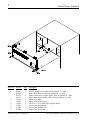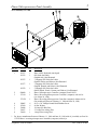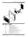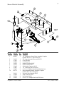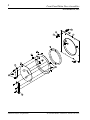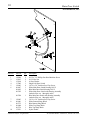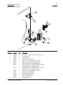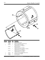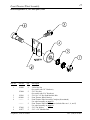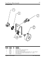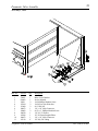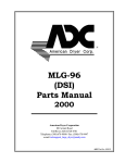
1
ML-95 Parts Manual
1996 Thru February 1999
American Dryer Corporation
88 Currant Road
Fall River, MA 02720-4781
Telephone: (508) 678-9000 / Fax: (508) 678-9447
E-mail: [email protected]
www.amdry.com
082997DMG/abe
ADC Part No. 450155
Retain This Manual In A Safe Place For Future Reference
American Dryer Corporation products embody advanced concepts in engineering, design, and safety. If this product is
properly maintained, it will provide many years of safe, efficient, and trouble-free operation.
ONLY qualified technicians should service this equipment.
OBSERVE ALL SAFETY PRECAUTIONS displayed on the equipment or specified in the installation manual included with
the dryer.
The following “FOR YOUR SAFETY” caution must be posted near the dryer in a prominent location.
FOR YOUR SAFETY
POUR VOTRE SÉCURITÉ
Do not store or use gasoline or
other flammable vapors and
liquids in the vicinity of this or
any other appliance.
Ne pas entreposer ni utiliser d’essence
ni d’autres vapeurs ou liquides
inflammables à proximité de cet
appareil ou de tout autre appareil.
We have tried to make this manual as complete as possible and hope you will find it useful. ADC reserves the right to make
changes from time to time, without notice or obligation, in prices, specifications, colors, and material, and to change or
discontinue models.
Important
For your convenience, log the following information:
DATE OF PURCHASE ____________________________
ML-95 Phase 6
MODEL NO. __________________________________________
RESELLER’S NAME _______________________________________________________________________________________
Serial Number(s)
________________________________________________________________________________________
________________________________________________________________________________________
________________________________________________________________________________________
Replacement parts can be obtained from your reseller or the ADC factory. When ordering replacement parts from the factory,
you can FAX your order to ADC at (508) 678-9447 or telephone your order directly to the ADC Parts Department at (508)
678-9000. Please specify the dryer model number and serial number in addition to the description and part number, so that
your order is processed accurately and promptly.
The illustrations on the following pages may not depict your particular dryer exactly. The illustrations are a composite of
the various dryer models. Be sure to check the descriptions of the parts thoroughly before ordering.
“IMPORTANT NOTE TO PURCHASER”
Information must be obtained from your local gas supplier on the instructions
to be followed if the user smells gas. These instructions must be posted in a
prominent location near the dryer.
Table of Contents
Control Door Assembly .......................................................................................................................... 2
Phase 6 Microprocessor Panel Assembly for models mfd. as of February 11, 1998 .................................. 3
Phase 6 Microprocessor Panel Assembly for models mfd. prior to February 11, 1998 .............................. 4
Sensor Bracket Assembly ....................................................................................................................... 5
Front Panel/Main Door Assemblies for models mfd. as of October 24, 1997 ....................................... 6, 7
Front Panel/Main Door Assemblies for models mfd. prior to October 24, 1997 ................................... 8, 9
Main Door Switch for models mfd. as of October 24, 1997 .................................................................. 10
Main Door Switch for models mfd. prior to October 24, 1997 ...............................................................11
Lint Door Assembly ........................................................................................................................ 12, 13
Basket (Tumbler) Assembly .................................................................................................................. 14
Front Thruster Wheel Assembly for models mfd. between September 15, 1997 and April 6, 1998 ......... 15
Front Thruster Wheel Assembly for models mfd. prior to September 15, 1997....................................... 16
Rear Thruster Wheel Assembly for models mfd. between September 15, 1997 and April 6, 1998 .......... 17
Rear Thruster Wheel Assembly for models mfd. prior to September 15, 1997........................................ 18
Front Thruster Wheel Assembly for models mfd. as of April 6, 1998 ...................................................... 19
Rear Thruster Wheel Assembly for models mfd. as of April 6, 1998 ....................................................... 20
Idler Shaft Assembly for models mfd. as of December 15, 1997 ............................................................ 21
Idler Shaft Assembly for models mfd. prior to December 15, 1997 ........................................................ 22
Drive Shaft Assembly for models mfd. as of December 15, 1997 ........................................................... 23
Drive Shaft Assembly for models mfd. prior to December 15, 1997 ....................................................... 24
Drive Motor Assembly.......................................................................................................................... 25
Blower (Fan/Impellor) Motor Assembly ................................................................................................ 26
Sail Switch Assembly ............................................................................................................................ 27
Blower (Fan/Impellor) Wheel Assembly (with Air Jet) for models mfd. as of July 1, 1998 ................. 28, 29
Blower (Fan/Impellor) Wheel Assembly (without Air Jet) for models mfd. prior to July 1, 1998 ........ 30, 31
Burner Assembly ............................................................................................................................ 32, 33
Reversing Relay Panel Assembly for 208/230/240/380/416 Volt Models Only ................................. 34, 35
Reversing Relay Panel Assembly for 460/480 Volt Models Only ............................................................ 36
Transition Piece Assembly with Damper for models mfd. as of September 12, 1997 ............................... 37
Exhaust Adapter Assembly for models mfd. prior to September 12, 1997 .............................................. 38
Pneumatic Valve Assembly for models mfd. as of July 1, 1998 ............................................................... 39
2
Control Door Assembly
Illus. No.
Part No.
Qty.
1
882093
882092
881732
881731
112368
160005
150309
102505
102601
102600
1
1
1
1
1
2
9
1
1
1
2
3
4
5
6
7
American Dryer Corporation
Description
White Control Door Assembly (As of February 11, 1998)
Blue Control Door Assembly (As of February 11, 1998)
White Control Door Assembly ONLY (Prior to February 11, 1998)
Blue Control Door Assembly ONLY (Prior to February 11, 1998)
Milnor Logo ONLY
Spring Turn Latch (2-piece)
#10-16 x 1/2” Hex Head TEK Crimptite Screw
Control Door Support Rod
Control Door Retainer Clip
Control Door Rod Catch
88 Currant Road / Fall River, MA 02720-4781
3
Phase 6 Microprocessor Panel Assembly
As of February 11, 1998
Illus. No.
Part No.
Qty.
1
112537
112276
1
1
112275
1
112277
1
112278
1
824480
137124
1
1
137122*
1
150005
153010
136048
136017
136019
6
6
1
1
1
2
3
4
5
6
7
8
*
Description
Phase 6 OPL Keyboard (touch pad)
OPL Stick-On Labels
(English Only) Not Illustrated
3 Language OPL Stick-On Labels
(Spanish, Italian, and Hebrew) Not Illustrated
3 Language OPL Stick-On Labels
(English, Spanish, and Hebrew) Not Illustrated
5 Language OPL Stick-On Labels
(Italian, Dutch, French, German, and Chinese) Not Illustrated
Phase 6 Microprocessor Controller (computer) Panel ONLY
Phase 6 Reversing Microprocessor Controller (computer) with Air Jet
(As of June 26, 1998)
Phase 6 Reversing Microprocessor Controller (computer) without Air Jet
(For models mfd. between February 11, 1998 and June 26, 1998)
#6-32 x 3/4” Phillips Round Head Machine Screw
#6 Star Washer
1/8-Amp (Slo Blo) Fuse
3.5-Amp (Fast Acting) Fuse
1-Amp (Fast Acting) Fuse
For dryers manufactured between February 11, 1998 and June 26, 1998 with air jet added, use Part No.
137124 Phase 6 reversing microprocessor controller (computer) with air jet.
Telephone: (508) 678-9000
Fax: (508) 678-9447
4
Phase 6 Microprocessor Panel Assembly
Prior to February 11, 1998
Illus. No.
Part No.
Qty.
1
112537
112276
1
1
112275
1
112277
1
112278
1
137116
137118
137121
150005
153010
881730
1
1
1
6
6
1
2
3
4
5
6
7
American Dryer Corporation
Description
Phase 6 OPL Keyboard (touch pad)
OPL Stick-On Labels
(English Only) Not Illustrated
3 Language OPL Stick-On Labels
(Spanish, Italian, and Hebrew) Not Illustrated
3 Language OPL Stick-On Labels
(English, Spanish, and Hebrew) Not Illustrated
5 Language OPL Stick-On Labels
(Italian, Dutch, French, German, and Chinese) Not Illustrated
Phase 6 Microprocessor Controller (computer)
Phase 6 OPL Input/Output (I/O) Board, Reversing
12” Ribbon Cable Assembly
#6-32 x 3/4” Phillips Round Head Machine Screw
#6 Star Washer
Microprocessor Controller (computer) Panel ONLY
88 Currant Road / Fall River, MA 02720-4781
Sensor Bracket Assembly
Illus. No.
Part No.
Qty.
1
880251
1
2
3
4
5
6
7
8
9
10
130103
153010
152000
121028
122701
122605
154007
150005
881710
1
2
2
2
4
1
2
2
1
11
12
13
390121
122604
122700
150301
1
1
4
2
Telephone: (508) 678-9000
5
Description
1/4” Temperature Sensor Probe Assembly Complete
(includes illus. nos. 1 and 5 through 8)
225º Large Automatic Thermostat ONLY
#6 Star Washer
#6-32 Hex Nut
Insulated Terminal ONLY
Socket Terminal ONLY
4-Pin Socket Connector ONLY
1/4” Tinnerman Push-on Fastener
#6-32 x 1/4” Phillips Round Head Machine Screw
Sensor Mounting Bracket Assembly Complete
(includes illus. nos. 1 through 10)
Universal Sensor Bracket ONLY
4-Pin Connector ONLY
Pin Terminal ONLY
#8-18 x 7/16” Phillips Pan Head TEK Screw
Fax: (508) 678-9447
6
Front Panel/Main Door Assemblies
As of October 24, 1997
American Dryer Corporation
88 Currant Road / Fall River, MA 02720-4781
Front Panel/Main Door Assemblies
7
As of October 24, 1997
Illus. No.
Part No.
Qty.
1
881804
1
881696
1
881805
1
881762
1
102214
170730
102357
881689
1
1
1
1
881761
1
9
881684
881756
881806
881807
881740
881739
881688
881737
881685
881757
150120
1
1
6
6
6
6
1
1
1
1
1
10
11
12
13
14
15
16
151010
122351
122419
132387
132395
170330
154215
1
1
1
1
1
1
2
2
3
4
5
6
7
8
Telephone: (508) 678-9000
Description
White Front Panel Assembly
(includes illus. nos. 1, 15, and 16)
For models mfd. as of December 3, 1997
White Front Panel Assembly
(includes illus. nos. 1, 15, and 16)
For models mfd. prior to December 3, 1997
Blue Front Panel Assembly
(includes illus. nos. 1, 15, and 16)
For models mfd. as of December 3, 1997
Blue Front Panel Assembly
(includes illus. nos. 1, 15, and 16)
For models mfd. prior to December 3, 1997
29-7/8” Door Glass
Door Glass Adhesive (10.3 oz. cartridge)
Main Door Gasket
White Main Door Assembly Complete
(includes illus. nos. 2 through 10)
Blue Main Door Assembly Complete
(includes illus. nos. 2 through 10)
White Main Door Ring
Blue Main Door Ring
1/4-20 Free Spin Wash Nut (White)
1/4-20 Free Spin Wash Nut (Blue)
1/4-20 x 5/8” (White) Carriage Bolt
1/4-20 x 5/8” (Blue) Carriage Bolt
White Main Door Handle
Blue Main Door Handle
White Main Door Hinge
Blue Main Door Hinge
Main Door Latch Screw
(#10-32 Dome Hex Head Screw)
#10-32 Acorn Nut
“EMERGENCY STOP” Push-Pull Button
“EMERGENCY STOP” Nameplate
Normally Closed (N.C.) Contact Block
Normally Closed (N.C.) Contact Block with Base
Friction Door Latch
5/32” Pop Rivet
Fax: (508) 678-9447
8
Front Panel/Main Door Assemblies
Prior to October 24, 1997
American Dryer Corporation
88 Currant Road / Fall River, MA 02720-4781
Front Panel/Main Door Assemblies
9
Prior to October 24, 1997
Illus. No.
Part No.
Qty.
1
881741
881760
151011
881817
1
1
3
1
881822
1
881815
1
881819
1
151011
102210
170730
102112
102356
881729
881824
881728
881821
122351
122419
132387
132395
9
1
1
2
1
1
1
1
1
1
1
1
1
2
3
4
5
6
7
8
9
10
11
12
Telephone: (508) 678-9000
Description
White Main Door Handle
Blue Main Door Handle
5/16-18 Acorn Nut
White Front Panel/Main Door Assemblies with “EMERGENCY STOP”
Button (includes illus. nos. 1 through 12)
Blue Front Panel/Main Door Assemblies with “EMERGENCY STOP”
Button (includes illus. nos. 1 through 12)
White Front Panel/Main Door Assemblies without “EMERGENCY STOP”
Button (includes illus. nos. 1 through 8)
Blue Front Panel/Main Door Assemblies without “EMERGENCY STOP”
Button (includes illus. nos. 1 through 8)
5/16-18 Acorn Nut
20-7/16” Door Glass
Door Glass Adhesive (10.3 oz. cartridge)
Door Magnet (5/16” x 1/4” x 34-3/4”)
Main Door Gasket (13-1/6” x 1-3/8” x 97-1/2”)
White Front Panel ONLY for “EMERGENCY STOP”
Blue Front Panel ONLY for “EMERGENCY STOP”
White Front Panel ONLY
Blue Front Panel ONLY
“EMERGENCY STOP” Push-Pull Button
“EMERGENCY STOP” Nameplate
Normally Closed (N.C.) Contact Block
Normally Closed (N.C.) Contact Block with Base
Fax: (508) 678-9447
10
Main Door Switch
As of October 24, 1997
Illus. No.
Part No.
Qty.
1
2
3
4
5
6
150006
152013
153010
137005
150443
881687
881695
881702
2
2
2
1
4
1
1
1
881700
1
150443
881441
881735
881440
881736
153031
2
1
1
1
1
1
7
8
9
10
American Dryer Corporation
Description
#6-32 x 7/8” Phillips Pan Head Machine Screw
#6-32 Hex Nut
#6 Star Washer
Single Pole Door Switch
1/4-20 x 3/4” Stainless Steel Cap Screw
White Main Door Switch Housing ONLY
Blue Main Door Switch Housing ONLY
White Main Door Switch with Housing Assembly
(includes illus. nos. 1 through 4 and 6)
Blue Main Door Switch with Housing Assembly
(includes illus. nos. 1 through 4 and 6)
1/4-20 x 3/4” Stainless Steel Cap Screw
White Bottom Hinge Block
Blue Bottom Hinge Block
White Top Hinge Block
Blue Top Hinge Block
Nylon Washer
88 Currant Road / Fall River, MA 02720-4781
11
Main Door Switch
Prior to October 24, 1997
Illus. No.
Part No.
Qty.
1
2
3
4
5
6
150006
152013
153010
137005
150443
881726
881727
881698
2
2
2
1
4
1
1
1
881699
1
150443
881441
881735
881440
881736
153031
2
1
1
1
1
1
7
8
9
10
Telephone: (508) 678-9000
Description
#6-32 x 7/8” Phillips Pan Head Machine Screw
#6-32 Hex Nut
#6 Star Washer
Single Pole Door Switch
1/4-20 x 3/4” Stainless Steel Cap Screw
White Main Door Switch Housing ONLY
Blue Main Door Switch Housing ONLY
White Main Door Switch with Housing Assembly
(includes illus. nos. 1 through 4 and 6)
Blue Main Door Switch with Housing Assembly
(includes illus. nos. 1 through 4 and 6)
1/4-20 x 3/4” Stainless Steel Cap Screw
White Bottom Hinge Block
Blue Bottom Hinge Block
White Top Hinge Block
Blue Top Hinge Block
Nylon Washer
Fax: (508) 678-9447
12
American Dryer Corporation
Lint Door Assembly
88 Currant Road / Fall River, MA 02720-4781
13
Lint Door Assembly
Illus. No.
Part No.
Qty.
1
882115
1
881724
1
882114
1
881811
1
881725
1
881812
1
2
3
117605
800150
6
1
4
5
6
7
8
9
10
11
12
160009
160001
881723
881810
150309
122116
300400
390136
150301
---------
1
1
1
1
11
1
1
1
2
1
13
14
824807
881734
1
1
881733
1
115900
152000
102358
3
12
1
15
16
17
Telephone: (508) 678-9000
Description
White Lint Door Assembly ONLY
(includes illus. nos. 1 and 2)
White Lint Door and Panel Assembly for models with Knob Latch
(includes illus. nos. 1, 2, and 6)
Blue Lint Door Assembly ONLY
(includes illus. nos. 1 and 2)
Blue Lint Door and Panel Assembly for models with Knob Latch
(includes illus. nos. 1, 2, and 6)
White Lint Door Assembly for models with Door Lock
(includes illus. nos. 1, 2, and 6)
Blue Lint Door Assembly for models with Door Lock
(includes illus. nos. 1, 2, and 6)
1/4” Noise Suppressor Tape (sold by the foot)
Knob Latch Kit
(includes illus. nos. 3 and 4)
Lock Cam ONLY
Lint Door Lock with Key
White Lint Door Front Panel
Blue Lint Door Front Panel
#10-16 x 1/2” Hex Head TEK Crimptite Screw
Normally Open (N.O.) Lint Door Switch - 24 VAC
Lint Door Switch Bracket
Lint Door Switch Bracket Cover
#8 x 7/16” Phillips Pan Head TEK Screw
Sensor Bracket
(refer to Sensor Bracket Assembly on page 5)
Rotational Sensor Assembly
Lint Screen (15-7/8” x 37”) with foam gasket
For models mfd. as of August 22, 1997
Lint Screen (16-3/8” x 37”) with foam gasket
For models mfd. prior to August 22, 1997
Drive Wheel Felt
Pop Rivet
Wrapper Gasket
Fax: (508) 678-9447
14
Basket (Tumbler) Assembly
Illus. No.
Part No.
Qty.
1
882100
170068
881722
4
4
1
881703
1
881721
1
881767
1
150123
102102
154200
40
1
1
2
3
4
5
American Dryer Corporation
Description
Basket (Tumbler) Side
Stainless Steel Basket (Tumbler) Side
Basket (Tumbler) Assembly
(includes illus. nos. 1 through 3)
Basket (Tumbler)
(includes illus. nos. 2, 4, and 5)
Stainless Steel Basket (Tumbler) Assembly
(includes illus. nos. 1 through 3)
Stainless Steel Basket (Tumbler)
(includes illus. nos. 2, 4, and 5)
1/4-20 x 1/4” Socket Button Head Screw
Rotational Sensor Magnet
5/32” Pop Rivet
88 Currant Road / Fall River, MA 02720-4781
15
Front Thruster Wheel Assembly
Between September 15, 1997 and April 6, 1998
Illus. No.
Part No.
Qty.
1
150220
2
152004
2
150501
882096
--------
2
2
2
--------
2
153001
154277
2
2
2
3
4
5
6
Telephone: (508) 678-9000
Description
3/8-24 Hex Nut
(for models with 3/8” Hardware)
5/16” Hex Nut
(for models with 5/16” Hardware)
5/16-18 x 3/4” Hex Head Machine Bolt
Front Thruster Wheel Bracket
Front Thruster Wheel Assembly Complete (discontinued)
Use wheel assembly on page 19
Front Thruster Wheel with hardware (includes illus. nos. 1, 4, and 5)
Use wheel assembly on page 19
5/16” Flat Washer
5/16” x 3/8” Shoulder Bolt
Fax: (508) 678-9447
16
Front Thruster Wheel Assembly
Prior to September 15, 1997
Illus. No.
Part No.
Qty.
1
2
3
4
152004
150501
882097
881758
180046
153001
1
2
1
1
1
1
5
American Dryer Corporation
Description
5/16” Hex Nut
5/16-18 x 3/4” Hex Head Machine Bolt
Front Thruster Wheel Bracket
Front Thruster Wheel Assembly
Front Thruster Wheel ONLY
5/16” Flat Washer
88 Currant Road / Fall River, MA 02720-4781
17
Rear Thruster Wheel Assembly
Between September 15, 1997 and April 6, 1998
Illus. No.
Part No.
Qty.
1
2
3
4
154277
-------153001
150220
1
1
2
2
152004
2
881752
881753
150301
1
1
4
5
6
Telephone: (508) 678-9000
Description
5/16” x 3/8” Shoulder Bolt
Rear Thruster Wheel with hardware (use wheel assembly on page 20)
5/16” Flat Washer
3/8-24 Hex Nut
(for models with 3/8” Hardware)
5/16” Hex Nut
(for models with 5/16” Hardware)
White Rear Thruster Wheel Cover
Blue Rear Thruster Wheel Cover
#8-18 x 7/16” Phillips Pan Head TEK Screw
Fax: (508) 678-9447
18
Rear Thruster Wheel Assembly
Prior to September 15, 1997
Illus. No.
Part No.
Qty.
1
2
3
4
152004
153001
180046
881752
881753
150301
1
1
1
1
1
4
5
American Dryer Corporation
Description
5/16” Hex Nut
5/16” Flat Washer
Rear Thruster Wheel ONLY
White Rear Thruster Wheel Cover
Blue Rear Thruster Wheel Cover
#8-18 x 7/16” Phillips Pan Head TEK Screw
88 Currant Road / Fall River, MA 02720-4781
19
Front Thruster Wheel Assembly
As of April 6, 1998
Illus. No.
Part No.
Qty.
1
2
3
4
150220
150501
882096
881720
881988
153001
1
2
1
1
1
1
5
Telephone: (508) 678-9000
Description
3/8-24 Hex Nut
5/16-18 x 3/4” Hex Head Machine Bolt
Front Thruster Wheel Bracket
Front Thruster Wheel Assembly (includes illus. nos. 1 and 3 through 5)
Front Thruster Wheel ONLY (includes illus. nos. 1, 4, and 5)
5/16” Flat Washer
Fax: (508) 678-9447
20
Rear Thruster Wheel Assembly
As of April 6, 1998
Illus. No.
Part No.
Qty.
1
2
3
4
150220
153001
881988
881752
881753
150301
150501
882096
1
1
1
1
2
4
2
2
5
6
7
American Dryer Corporation
Description
3/8-24 Hex Nut
5/16” Flat Washer
Front Thruster Wheel ONLY (includes illus. nos. 1 through 3)
White Rear Thruster Wheel Cover
Blue rear Thruster Wheel Cover
#8-18 x 7/16” Phillips Pan Head Screw
5/16-18 x 3/4” Hex Head Machine Bolt
Front Thruster Wheel Bracket
88 Currant Road / Fall River, MA 02720-4781
21
Idler Shaft Assembly
As of December 15, 1997
Illus. No.
Part No.
Qty.
1
881825
1
2
3
4
5
6
7
8
9
390134
180037
180038
880205
152004
153002
153001
859008
100704
1
2
2
2
4
4
4
2
2
Telephone: (508) 678-9000
Description
Idler Shaft Assembly Complete
(includes illus. nos. 1 through 7)
For models mfd. as of December 15, 1997
Drive Shaft ONLY
6” Drive Wheel
1” Taperlock
1” Pillow Block Bearing
5/16-18 Hex Nut
5/16” Lock Washer
5/16” Flat Washer
Bearing Bolt Plate Assembly
1/4” x 1/4” x 1 3/4” Key
Fax: (508) 678-9447
22
Idler Shaft Assembly
Prior to December 15, 1997
Illus. No.
Part No.
Qty.
1
881718
1
2
3
4
5
6
7
390009
180039
180006
100205
152004
153002
153001
1
2
2
2
4
4
4
American Dryer Corporation
Description
Idler Shaft Assembly Complete
(includes illus. nos. 1 through 7)
For models mfd. prior to December 15, 1997
Idler Shaft ONLY
6” Wheel
1” Trantorque
1” Pillow Block Bearing
5/16” Hex Nut
5/16” Lock Washer
5/16” Flat Washer
88 Currant Road / Fall River, MA 02720-4781
23
Drive Shaft Assembly
As of December 15, 1997
Illus. No.
Part No.
Qty.
1
881826
390154
180037
180038
880205
152004
153002
153001
859008
100700
101209
100704
1
1
2
2
2
4
4
4
2
1
1
2
2
3
4
5
6
7
8
9
10
11
Telephone: (508) 678-9000
Description
Drive Shaft Assembly Complete (includes illus. nos. 1 through 11)
Drive Shaft ONLY
6” Drive Wheel
1” Taperlock
1” Pillow Block Bearing
5/16”-18 Hex Nut
5/16” Lock Washer
5/16” Flat Washer
Bearing Bolt Plate Assembly
1/4” x 1/4” x 1 1/16” Key
9” Pulley
1/4” x 1/4” x 1 3/4” Key
Fax: (508) 678-9447
24
Drive Shaft Assembly
Prior to December 15, 1997
Illus. No.
Part No.
Qty.
1
881717
1
2
3
4
5
6
7
8
9
390008
180039
180006
880205
152004
153002
153001
100700
101209
1
2
2
2
4
4
4
1
1
American Dryer Corporation
Description
Drive Shaft Assembly Complete
(includes illus. nos. 1 through 9)
For models mfd. prior to December 15, 1997
Drive Shaft ONLY
6” Wheel
1” Trantorque
1” Pillow Block Bearing
5/16” Hex Nut
5/16” Lock Washer
5/16” Flat Washer
1/4” x 1/4” x 1-1/16” Key
9” Pulley
88 Currant Road / Fall River, MA 02720-4781
25
Drive Motor Assembly
Illus. No.
Part No.
Qty.
1
881715
1
881716
1
859012
150501
153002
153001
181106
152004
101132
101130
100174
1
7
11
11
1
4
1
1
1
100151
1
100174
1
100175
1
150523
1
2
3
4
5
6
7
8
9
Telephone: (508) 678-9000
Description
Drive Motor Assembly Complete - 60 Hz
(includes illus. nos. 1 through 7 and 9)
Drive Motor Assembly Complete - 50 Hz
(includes illus. nos. 1 through 7 and 9)
Drive Motor Mount Assembly ONLY
5/16-18 x 3/4” Hex Head Machine Bolt
5/16” Lock Washer
5/16” Flat Washer
1/2 HP / 3ø / 50/60 Hz Totally Enclosed, Fan-Cooled (T.E.F.C.) Motor
5/16” Hex Nut
5/8” Bore x 2” Pulley - 60 Hz
5/8” Bore x 2-1/2” Pulley - 50 Hz
AX-53 Cogged Belt - 60 Hz
(for models mfd. as of August 8, 1997)
AX-54 Cogged Belt - 60 Hz
(for models mfd. prior to August 8, 1997)
AX-54 Cogged Belt - 50 Hz
(for models mfd. as of May 13, 1998)
AX-55 Cogged Belt - 50 Hz
(for models mfd. prior to May 13, 1998)
1/4-20 x 3/4” Hex Washer TEK Screw
Fax: (508) 678-9447
26
Blower (Fan/Impellor) Motor Assembly
Illus. No.
Part No.
Qty.
1
881713
1
881714
1
859039
181105
150504
153002
153001
152004
150514
101135
101185
101194
1
1
4
8
8
6
2
1
1
1
2
3
4
5
6
7
8
9
American Dryer Corporation
Description
Blower (Fan/Impellor) Motor Assembly Complete - 60 Hz
(includes illus. nos. 1 through 9)
Blower (Fan/Impellor) Motor Assembly Complete - 50 Hz
(includes illus. nos. 1 through 9)
Blower (Fan/Impellor) Motor Slide Assembly ONLY
3 HP / 3ø / 50/60 Hz Totally Enclosed, Non-Vent (T.E.N.V.) Motor
5/18-18 x 1” Hex Head Machine Bolt
5/16” Lock Washer
5/16” Flat Washer
5/16” Hex Nut
5/16-18 X 2-1/4” Hex Bolt
2B x 5.4 Pulley - 60 Hz
2B x 6.2 Pulley - 50 Hz
1-3/8” x SDS Bushing
88 Currant Road / Fall River, MA 02720-4781
27
Sail Switch Assembly
Illus. No.
Part No.
Qty.
1
2
3
4
5
6
7
8
9
319203
319202
319201
319200
154004
154002
150309
150303
122200
881706
1
1
1
1
1
1
4
2
1
1
10
105500
1
Telephone: (508) 678-9000
Description
Sail Switch Mounting Bracket
Sail Switch Damper (flat)
Sail Switch Box Cover
Sail Switch Box
Twin Speed Nut
1/8” Push-on Fastener
#10-16 x 1/2” Hex Head TEK Crimptite Screw
#4 x 3/4” Pan Head “A” Machine Screw
Sail Switch ONLY
Sail Switch Box Assembly Complete
(includes illus. nos. 1 through 10)
Sail Switch Actuator Rod
Fax: (508) 678-9447
28
Blower (Fan/Impellor) Wheel Assembly (with Air Jet)
As of July 1, 1998
American Dryer Corporation
88 Currant Road / Fall River, MA 02720-4781
29
Blower (Fan/Impellor) Wheel Assembly (with Air Jet)
As of July 1, 1998
Illus. No.
1
2
3
4
5
6
7
8
9
10
11
12
13
14
15*
16
17
18
19
20
21
*
Part No.
Qty.
101215
101216
100240
100701
859014
390053
152004
859013
153001
153002
150501
100615
881711
1
1
2
2
1
1
8
1
12
12
4
1
1
881712
1
153050
152012
100149
100176
143100
143287
143259
143110
882101
150309
1
2
2
2
2.5”
1
2
9’
1
2
Description
5/8” x SH Bushing
2B x 4.2 Pulley - 50/60 Hz
1” Flange Bearing
3/16” x 3/16” x 1” Key
Idler Mount - Top
Impellor (Fan/Blower) Shaft
5/16-18 Hex Nut
Impellor (Fan/Blower) Cover
5/16” Flat Washer
5/16” Lock Washer
5/16-18 x 3/4” Hex Head Machine Bolt
9-15/16” x 5” Squirrel Cage Fan (Impellor/Blower)
Blower (Fan/Impellor) Wheel Assembly Complete - 60 Hz
(includes illus. nos. 1 through 14)
Blower (Fan/Impellor) Wheel Assembly Complete - 50 Hz
(includes illus. nos. 1 through 14)
1/2” Flat Washer
1/2-20 Hex Nut
BX-44 Cogged Belt - 60 Hz
BX-46 Cogged Belt - 50 Hz
1/4” Aluminum Tubing
Tee Fitting
Bulkhead Fitting
1/4” Poly Flo Tubing
Air Jet Mounting Plate
#10-16 x 1/2 Hex Head Crimptite Screw
Replace in matched sets (both belts).
Telephone: (508) 678-9000
Fax: (508) 678-9447
30
Blower (Fan/Impellor) Wheel Assembly (without Air Jet)
Prior to July 1, 1998
American Dryer Corporation
88 Currant Road / Fall River, MA 02720-4781
31
Blower (Fan/Impellor) Wheel Assembly (without Air Jet)
Prior to July 1, 1998
Illus. No.
1
2
3
4
5
6
7
8
9
10
11
12
13
14
15*
*
Part No.
Qty.
101215
101216
100240
100701
859014
390053
152004
859013
153001
153002
150501
100615
881711
1
1
2
2
1
1
8
1
12
12
4
1
1
881712
1
153050
152012
100149
100176
1
2
2
2
Description
5/8” x SH Bushing
2B x 4.2 Pulley - 50/60 Hz
1” Flange Bearing
3/16” x 3/16” x 1” Key
Idler Mount - Top
Impellor (Fan/Blower) Shaft
5/16-18 Hex Nut
Impellor (Fan/Blower) Cover
5/16” Flat Washer
5/16” Lock Washer
5/16-18 x 3/4” Hex Head Machine Bolt
9-15/16” x 5” Squirrel Cage Fan (Impellor/Blower)
Blower (Fan/Impellor) Wheel Assembly Complete - 60 Hz
(includes illus. nos. 1 through 14)
Blower (Fan/Impellor) Wheel Assembly Complete - 50 Hz
(includes illus. nos. 1 through 14)
1/2” Flat Washer
1/2-20 Hex Nut
BX-44 Cogged Belt - 60 Hz
BX-46 Cogged Belt - 50 Hz
Replace in matched sets (both belts).
Telephone: (508) 678-9000
Fax: (508) 678-9447
32
American Dryer Corporation
Burner Assembly
88 Currant Road / Fall River, MA 02720-4781
33
Burner Assembly
Illus. No.
Part No.
Qty.
16
17
18
142924
331291
150309
142829
141300
142701
142601
142710
142504
142734
390125
140026
882098
140411
331291
141208
140836
140855
141123
390124
---------
1
1
20
1
1
1
1
1
1
1
1
1
1
1
1
1
3
3
3
1
1
19
20
21
22
23
24
25
26
390098
881597
128921
150001
151000
130401
319703
881709**
1
1
1
2
2
1
1
1
881708**
1
881707
881498*
335031
151001
881797
1
1
1
2
1
1
2
3
4
5
6
7
8
9
10
11
12
13
14
15*
27
28
29
Description
1” to 3/4” Reducing Coupling
Pipe Bracket
#10-16 x 1/2” Hex Head TEK Crimptite Screw
3/4” x 20” Nipple
3/4” Union Shut-off
3/4” Closed Nipple
3/4” Union
3/4” x 4” Nipple
3/4” x 90º Elbow
3/4” x 5-1/2” Nipple
Pipe Bracket
3/4” 24 VAC Redundant (natural gas) Gas Valve
3/4” x 24” VAC Redundant (liquid propane [L.P.] gas) Gas Valves
24 VAC Gas Valve Liquid Propane (L.P.) Conversion Kit
Pipe Bracket
3-Port Manifold
#10 Burner Orifice (natural gas) ONLY
#33 Burner Orifice (liquid propane [L.P.] gas) ONLY
Burner Tube ONLY
Burner Tube Support ONLY
Sail Switch
(refer to Sail Switch Assembly on page 27)
Burner Box Cover Plate ONLY
Hot Surface Ignition (HSI) Ignitor
Hot Surface Ignition (HSI) Flame Sensor
#6-32 x 1/2” Phillips Round Head Machine Screw
#6-32 Pal Nut
330º Hi-Limit ONLY
Hi-Limit Bracket
Natural Gas Burner Assembly Complete
(includes illus. nos. 1 through 14 and 16 through 29)
For models mfd. with Natural Gas ONLY
Liquid Propane (L.P.) Gas Burner Assembly Complete
(includes illus. nos. 1 through 14 and 16 through 29)
For models mfd. with Liquid Propane (L.P.) Gas ONLY
Burner Box ONLY
Hot Surface Ignition (HSI) L.P. Conversion Kit
Hot Surface Ignition (HSI) Module Mounting Bracket/Manifold Rest
#8-32 Pal Nut
Hot Surface Ignition (HSI) Module II
* Consult factory for elevations over 2,000 feet.
** Burner assemblies DO NOT include burner orifices, which must be ordered separately.
Telephone: (508) 678-9000
Fax: (508) 678-9447
34
Reversing Relay Panel Assembly
For 208/230/240/380/416 Volt Models ONLY
American Dryer Corporation
88 Currant Road / Fall River, MA 02720-4781
35
Reversing Relay Panel Assembly
For 208/230/240/380/416 Volt Models ONLY
Illus. No.
Part No.
Qty.
1
132467
132468
132445
150300
150008
120701
132448
132070
132082
881763
137060
137013
151000
152004
121012
153002
136008
136057
136057
881992
1
1
1
2
2
1
1
1
1
1
1
4
2
1
1
1
1
1
2
1
881991
1
881701
1
323743
150301
132457
132456
132454
1
1
1
1
1
2
3
4
5
6
7
8
9
10
11
12
13
14
15
16
17
18
Telephone: (508) 678-9000
Description
9-13-Amp Blower Overload (for 208/230/240 volt models Only)
4-6-Amp Blower Overload (for 380/416 volt models Only)
12-Amp 3ø Contactor - 24 VAC
#10 x 1/2” Hex Washer TEK Screw
#6-32 x 1-1/4” Phillips Round Head Machine Screw
4-Position Terminal Block
Reversing Contactor - 24 VAC
208-230/240 Volt Transformer ONLY
380/416 Volt Transformer ONLY
ML Transformer Termination Kit
Arc Suppressor (A.S.) Board
Nylon Standoff
#6-32 Pal Nut
5/16-18 Hex Nut
Ground Lug
5/16” Lock Washer
Fuse Holder ONLY
1/2-Amp (Slo Blo) Fuse (for 208/230/240 volt models Only)
1/2-Amp (Slo Blo) Fuse (for 380/416 volt models Only)
Reversing Relay Panel Assembly Complete
(includes illus. nos. 1 through 18)
For 208 volt models ONLY
Reversing Relay Panel Assembly Complete
(includes illus. nos. 1 through 18)
For 230/240 volt models ONLY
Reversing Relay Panel Assembly Complete
(includes illus. nos. 1 through 18)
For 380/416 volt Models ONLY
Relay Panel ONLY
#8-18 x 7/16” Phillips Pan Head TEK Screw
2.6-3.7-Amp Drive Motor Overload (for 208 volt models Only)
1.8-2.6-Amp Drive Motor Overload (for 230/240 volt models Only)
1.2-1.8-Amp Drive Motor Overload
For 380/416 volt - 50 Hz Models ONLY
For 460 volt - 60 Hz Models ONLY
Fax: (508) 678-9447
36
Reversing Relay Panel Assembly
For 460/480 Volt Models ONLY
Illus. No.
Part No.
Qty.
1
2
3
4
5
6
7
8
9
10
11
12
13
132468
132445
150300
150008
120701
132448
132067
137060
137013
152004
121012
153002
881615
1
1
2
2
1
1
1
1
4
1
1
1
1
14
15
16
17
881763
323743
151000
120768
135501
132454
1
1
2
2
1
1
American Dryer Corporation
Description
4-6-Amp Blower Overload (for 460/480 volt models Only)
12-Amp 3ø Contactor - 24 VAC
#10 x 1/2” Hex Washer TEK Screw
#6-32 x 1-1/4” Phillips Round Head Machine Screw
4-Position Terminal Block
Reversing Contactor - 24 VAC
460/480 Volt Transformer
Arc Suppressor (A.S.) Board
Nylon Standoff
5/16-18 Hex Nut
Ground Lug
5/16” Lock Washer
Reversing Relay Panel Assembly Complete
(includes illus. nos. 1 through 17)
ML Transformer Termination Kit
Relay Panel ONLY
#6-32 Pal Nut
Din Rail (sold by the inch)
1-Amp Double Pole Circuit Breaker
1.2-1.8-Amp Drive Motor Overload (for 460 volt Models Only)
88 Currant Road / Fall River, MA 02720-4781
37
Transition Piece Assembly with Damper
As of September 12, 1997
Illus. No.
Part No.
Qty.
1
881705
881809
152014
1
1
8
2
Telephone: (508) 678-9000
Description
White Transition Piece Assembly with Damper Complete
Blue Transition Piece Assembly with Damper Complete
1/4-20 Free Spin Wash Nut
Fax: (508) 678-9447
38
Exhaust Adapter Assembly
Prior to September 12, 1997
Illus. No.
Part No.
Qty.
1
881704
881808
152014
1
1
8
2
American Dryer Corporation
Description
White Exhaust Adapter Assembly without Damper
Blue Exhaust Adapter Assembly without Damper
1/4-20 Free Spin Wash Nut
88 Currant Road / Fall River, MA 02720-4781
Pneumatic Valve Assembly
39
As of July 1, 1998
Illus. No.
1
2
3
4
5
6
7
8
9
10
11
Part No.
Qty.
330987
836002
150111
152014
151000
100472
150002
100520
143268
100472
143110
1
1
2
2
2
1
2
1
1
1
9’
Telephone: (508) 678-9000
Description
Micro Valve Bracket
Air Jet Solenoid
1/4-20 Phillips Machine Screw
1/4-20 Free Spin Wash Nut
#6-32 Pal Nut
1/4” x 1/8” Male Connector
#6-32 x 1” Phillips Machine Screw
1/8” N.P.T. Silencer
1/8” 90º Brass Straight Elbow
1/4” x 1/8” Male Connector
1/4” Poly Flo Tubing
Fax: (508) 678-9447
ADC 450155
1 - 12/16/97-50
4 * 08/12/98-50
7 * 02/26/02-25
2 * 01/15/98-50
5 * 12/23/98-50
3 * 05/21/98-50
6 * 03/02/00-50