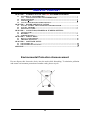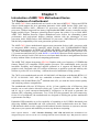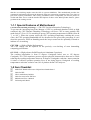
1
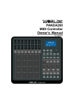
KM780V Rev: 1.0 USER'S MANUAL Of AMD 780V + SB700 Chipset M/B for Socket AM2+ 64-bit Dual Core AMD Processors Trademark: * Specifications and information contained in this documentation are furnished for information use only, and are subject to change at any time without notice, and should not be construed as a commitment by manufacturer. Manual Rev: EG100 (Release date: May, 2009) Environmental Safety Instruction z Avoid the dusty, humidity and temperature extremes. Do not place the product in any area where it may become wet. z 0 to 40 centigrade is the suitable temperature. (The figure comes from the request of the main chipset) z Generally speaking, dramatic changes in temperature may lead to contact malfunction and crackles due to constant thermal expansion and contraction from the welding spots’ that connect components and PCB. Computer should go through an adaptive phase before it boots when it is moved from a cold environment to a warmer one to avoid condensation phenomenon. These water drops attached on PCB or the surface of the components can bring about phenomena as minor as computer instability resulted from corrosion and oxidation from components and PCB or as major as short circuit that can burn the components. Suggest starting the computer until the temperature goes up. z The increasing temperature of the capacitor may decrease the life of computer. Using the close case may decrease the life of other device because the higher temperature in the inner of the case. z Attention to the heat sink when you over-clocking. The higher temperature may decrease the life of the device and burned the capacitor. Environmental Protection Announcement Do not dispose this electronic device into the trash while discarding. To minimize pollution and ensure environment protection of mother earth, please recycle. ii TABLE OF CONTENT CHAPTER 1 1-1 1-2 1-3 1-4 INTRODUCTION OF AMD 780V MOTHERBOARD SERIES FEATURES OF MOTHERBOARD .................................................................................... 1 1-1.1 SPECIAL FEATURES OF MOTHERBOARD.................................................... 2 ITEM CHECKLIST .............................................................................................................. 2 SPECIFICATION................................................................................................................... 3 LAYOUT DIAGRAM & JUMPER SETTING ................................................................... 4 CHAPTER 2 HARDWARE INSTALLATION CHAPTER 3 CONNCTORS, HEADERS & JUMPERS SETTING CHAPTER 4 USEFUL HELP CHAPTER 5 SOFTWARE SETUP 2-1 2-2 2-3 3-1 3-2 3-3 4-1 4-2 5-1 5-2 INSTALL SOCKET AM2 SUPPORTED AMD PROCESSOR ........................................ 5 INSTALL MEMORY............................................................................................................ 5 EXPANSION CARDS ........................................................................................................... 6 CONNECTORS ..................................................................................................................... 7 HEADERS .............................................................................................................................. 8 JUMPER SETTING .............................................................................................................. 12 HOW TO UPDATE BIOS..................................................................................................... 14 TROUBLE SHOOTING ....................................................................................................... 14 SOFTWARE LIST ................................................................................................................. 15 SOFTWARE INSTALLATION ............................................................................................ 15 APPENDIX ...............................................................................................................................17 Environmental Protection Announcement Do not dispose this electronic device into the trash while discarding. To minimize pollution and ensure environment protection of mother earth, please recycle. iii Chapter 1 Introduction of AMD 780V Motherboard Series 1-1 Features of motherboard The AMD 780V Series motherboards are based on the latest AMD780V Chipset and SB700 chipset which supports the new generation innovative 64-bit AMD Socket AM2+ dual core multi-tasking Socket AM2+ Athlon64 X2 processors and dual core AMD Phenom™ processors. With an integrated low-latency high-bandwidth DDR2 memory controller and the highly-scalable Hyper Transport technology-based system bus which is up to 2000 MHZ, AMD 780V Platform Processor Chipset motherboard series deliver the outstanding system performance and professional desktop platform solution with the advantages of new generation 64-bit AMD Socket AM2 Athlon64 X2 processors, AMD Phenom™ processors and the fully compatibility of the next generation operation system. The AMD 780V Series motherboards support new generation Socket AM2+ processors with an integrated DDR2 memory controller which provides with 333MHz/400MHz/533MHz memory clock frequencies for DDR2 667/ DDR2 800/ DDR2 1066 DDR2 Module up to 4GB. The whole motherboard series are embedded with SB700 chipset that provides ULTRA ATA 133 connectors and Serial ATA2 with RAID 0,1 and JBOD functions which support up to two IDE devices and six Serial ATA2 devices to accelerate hard disk drives and guarantee the data security without failure in advanced computing performance. The AMD 780V chipset incorporates HD 3100 Graphics with a core frequency of 350MHz that features DirectX 10.0 compliant 2D/3D graphics processor. This motherboard series provide incredible flexibility and unlimited upgrade potential as it supports all Radeon® PCI-E graphics cards. Designed with ATI’s unique architecture to optimize speed and stability, this solution is perfect for over-clocking – without the need of additional cooling systems. The 780V series motherboards provide 10/100/1000 LAN functions with Realtek RTL8111C PCI-E 10/100/1000 LAN. And the embedded 6-channel HD Audio CODEC is fully compatible with Sound Blaster Pro standards that offer you with the home cinema quality and satisfying software compatibility. The motherboards offer one PCI-Express x16 by 16 lane graphics slot of 8Gbyte/sec data transfer rate at each relative direction which gets 7 times of bandwidth more than AGP 8X and it’s up to a peak concurrent bandwidth of 16Gbyte/sec at full speed to guarantee the ultimate GPU computing performance. Two 32-bit PCI slots guarantee the rich connectivity for the I/O of peripherals; the motherboards are designed of tackling the profuse multimedia requirements nowadays. Embedded USB controller as well as capability of expanding to 8 of USB2.0 functional ports delivering 480Mb/s bandwidth and rich connectivity, these motherboards meet the future USB demands which are also equipped with hardware monitor function on system to monitor and protect your system and maintain your non-stop business computing. Some special features --- CPU Thermal Throttling/ CPU VID /OC-CON this motherboard are designed for power user to use the over-clocking function in more flexible ways. But please be caution 1 that the over-clocking maybe cause the fails in system reliabilities. This motherboard provides the guaranteed performance and meets the demands of the next generation computing. But if you insist to gain more system performance with variety possibilities of the components you choose, please be careful and make sure to read the detailed descriptions of these value added product features, please get them in the coming section. 1-1.1 Special Features of Motherboard CPU Thermal Throttling Technology --- (The CPU Overheat Protection Technology) To prevent the increasing heat from damage of CPU or accidental shutdown while at high workload, the CPU Thermal Throttling Technology will force CPU to enter partially idle mode from 87.5% to 12.5% according to preset CPU operating temperature in BIOS (from 40 ℃ to 90℃). When the system senses the CPU operating temperature reaching the preset value, the CPU operating bandwidth will be decreased to the preset idle percentage to cool down the processor. When at throttling mode the beeper sound can be optionally selected to indicate it is in working. CPU VID --- (Shift to Higher Performance) The CPU voltage can be adjusted for the precisely over-clocking of extra demanding computing performance. OC-CON --- (High-polymer Solid Electrolysis Aluminum Capacitors) The working temperature is from 55 degrees Centigrade below zero to 125 degrees Centigrade, OC-CON capacitors possess superior physical characteristics that can be while reducing the working temperature between 20 degrees Centigrade each time, intact extension 10 times of effective product operation lives, at not rising degrees Centigrade of working temperatures each time a relative one, life of product decline 10% only too. 1-2 Item Checklist 5 5 5 5 5 5 AMD780V Platform Processor Chipset based motherboard Cable for IDE CD for motherboard utilities Cable for Serial ATA IDE Port Motherboard User’s Manual I/O Back panel Shield 2 1-3 Specification Spec Description Design ∗ ∗ Chipset ∗ ∗ CPU Socket AM2+ Memory Socket Expansion Slot ∗ ∗ ∗ ∗ ∗ ∗ ∗ Integrate IDE and Serial ATA2 RAID ∗ ∗ Integrated VGA ∗ Micro ATX form factor 4 layers PCB size: 24.5x20.0cm AMD780V Chipset and AMD SB700 Chipset Support 64bit AMD AM2+ 940-Pin package utilizes Flip-Chip Pin Grid Array package compatible processor Support for HTT 1GHz dual core AMD Phenom processors Support HT 3.0 AMD Athlon 64 X2 processor 240-pin DDR2 Module socket x 2 Support 2 pcs DDR2 1066 / DDR2 800/DDR2 667 Modules Expandable to 4GB PCI-Express2.0 x16 by16 lane 1pcs delivers up to 16 GB/s of concurrent bandwidth. 32-bit PCI slot x 2 pcs One IDE controllers support PCI Bus Mastering, ATA PIO / DMA and the ULTRA DMA 33/66/100/133 functions that deliver the data transfer rate up to 133 MB/s. Six Serial ATA2 ports provide 300 MB/sec data transfer rate with RAID 0, 1, JBOD functions. 780V chipset integrated with HD3100 graphics with 350 MHz core Frequency DirectX 10.0 compliant 2D /3D graphics processor LAN ∗ ∗ Audio ∗ 6-channelALC662 HD Audio Codec integrated ∗ Audio driver and utility included BIOS Multi I/O ∗ ∗ ∗ ∗ ∗ ∗ ∗ ∗ ∗ ∗ ∗ Integrated RTL 8111C PCI-E 10/100 /1000 LAN chip Supports Fast Ethernet LAN function provide 10/100/1000 Mb /s data transfer rate Award 8MB SPI Flash ROM PS/2 keyboard and PS/2 mouse connectors VGA Connectorx1 DVI Connectorx1 HDMI Connector x1 USB2.0 port x 4 and headers x 2 Audio connector (Line-in, Line-out, MIC/ 6CH Audio) Floppy disk drive connector x1 Hard disk drive connector x1 Serial port header x1 HDMI_SPDIF Out header x1 3 1-4 Layout Diagram For KM780V model RJ-45 LAN VGA Connector Line-IN PS/2 Mouse HDMI Connector Line-OUT PS/2 Keyboard MIC-IN Coaxial SPDIF_Out Connector DVI Connector USB Connector Keyboard/USB Power (JP1) CPU FAN ATX 12V Power Connector PS2 KB/Mouse Port CPU Socket AM2+ SPDIF_Out Connector HDMI Connector DDR2 Socket x2 VGA over DVI Connector ATX Power Conn. USB Port RJ-45 Over USB Connector Audio Connector ATA 133 IDE Conn.(IDE1) SYSFAN2 AMD780V SYSFAN1 DDRII 128MB sideport RTL8111C Gigabit LAN PCI Express x16 Clear CMOS Jumper (JBAT) AMD SB700 Chipset Serial-ATAII Connector (SATA1~6) PCI Slots Power LED Header Speaker Header Realtek ALC662HD Audio Decode HDMI_SPDIF COM Header Audio Header Floppy Connector CD Audio In 4 USB headers Front Panel Connector 8MBit Flash SPI ROM BIOS Chapter 2 Hardware Installation 2-1 Install Socket AM2+ Supported AMD Processor This motherboard provides a 940-pin surface mount, Zero Insertion Force (ZIF) socket, referred to as the mPGA940 socket supports AMD Athlon64 processor in the 940 Pin package utilizes Flip-Chip Pin Grid Array package technology. The CPU that comes with the motherboard should have a cooling FAN attached to prevent overheating. If this is not the case, then purchase a correct cooling FAN before you turn on your system. WARNING! Be sure that there is sufficient air circulation across the processor’s heat sink and CPU cooling FAN is working correctly, otherwise it may cause the processor and motherboard overheat and damage, you may install an auxiliary cooling FAN, if necessary. To install a CPU, first turn off your system and remove its cover. Locate the ZIF socket and open it by first pulling the level sideways away from the socket then upward to a 90-degree angle. Insert the CPU with the correct orientation as shown below. The notched corner should point toward the end of the level. Because the CPU has a corner pin for two of the four corners, the CPU will only fit in the orientation as shown. Socket AM2+ Colden Arrow CPU ZIF mPGAB Socket When you put the CPU into the ZIF socket, No force require to insert of the CPU, then press the level to Locate position slightly without any extra force. 2-2 Install Memory The motherboards provide two 240-pin DDRII DUAL INLINE MEMORY MODULES (DIMM) sites for DDRII memory expansible to maximum memory size of 4GB DDRII SDRAM. Valid Memory Configurations of 4-DIMM Design Motherboard Bank 240-Pin DIMM PCS Bank 0, 1 (DIMM1) DDRII 1066/DDRII 800/DDRII 667 Bank 2, 3 (DIMM2) DDRII 1066/DDRII 800/DDRII 667 Total System Memory (Max. 2GB) 5 X1 X1 2 Maximum Capacity 2GB 2GB 4GB Generally, installing DDRII SDRAM modules to your motherboard is very easy, you can refer to figure 2-4 to see what a 240-Pin DDR2 1066/800/667 SDRAM module looks like. Figure 2-4 NOTE! When you install DIMM module fully into the DIMM socket the eject tab should be locked into the DIMM module very firmly and fit into its indention on both sides 2-3 Expansion Cards The motherboards offer one PCI-Express x16 by 16lane graphics slot of 8Gbyte/sec data transfer rate at each relative direction which gets 7 times of bandwidth more than AGP 8X and it’s up to a peak concurrent bandwidth of 16Gbyte/sec at full speed to guarantee the ultimate GPU computing performance. Two32-bit PCI slots guarantee the rich connectivity for the I/O of peripherals; the motherboards are designed of tackling the profuse multimedia requirements nowadays. PE1 / PCI-E x16 Slot 32-bit PCI Slot 6 Chapter 3 Connectors, Headers & Jumpers Setting 3-1 Connectors (1) Power Connector (24-pinblock) : ROW1 ROW2 ATXPWR1 PIN ROW1 ROW2 ROW1 ROW2 ATX Power Supply connector: This is a 1 3.3V 3.3V 2 3.3V -12V new defined 24-pins connector that 3 GND GND usually comes with ATX case. The ATX 4 5V Soft Power On Power Supply allows using soft power on 5 GND GND 6 5V GND momentary switch that connect from the 7 GND GND front panel switch to 2-pins Power On 8 Power OK -5V 9 +5V (for Soft Logic) +5V jumper pole on the motherboard. When 10 +12V +5V the power switch on the back of the ATX 11 +12V +5V power supply turned on, the full power 12 +3V GND will not come into the system board until the front panel switch is momentarily Pin 1 Pin 1 pressed. Press this switch again will turn 24-Pin off the power to the system board. 20-Pin ** We recommend that you use an ATX 12V Specification 2.0-compliant power supply unit (PSU) with a minimum of 350W power rating. This type has 24-pin and 4-pin power plugs. ** If you intend to use a PSU with 20-pin and 4-pin power plugs, make sure that the 20-pin power plug can provide at least 15A on +12V and the power supply unit has a minimum power rating of 350W. The system may become unstable or may not boot up if the power is inadequate. (2) (3) (4) (5) (6) ATX 12V Power Connector (8-pin block) : ATX12V This is a new defined 8-pins connector that usually comes with ATX Power Supply. The ATX Power Supply which fully supports AM2 processor must including this connector for support extra 12V voltage to maintain system power consumption. Without this connector might cause system unstable because the power supply can not provide sufficient current for system. PS/2 Mouse & PS/2 Keyboard Connector: KB The connectors are for PS/2 keyboard and PS/2 Mouse . USB Port connector: USB Port from CN5&UL1 The connectors are 4-pin connectors that connect USB devices to the system board. LAN Port connector: RJ-45 port from UL1 This connector is standard RJ-45 connector 10M/100Mb/1000Mb s data transfer rate for Network, Audio Line-In, Lin-Out, MIC Connector: CN3 This Connector is 3 phone Jack for LINE-OUT, LINE-IN, MIC Line-in : (BLUE) Audio input to sound chip Line-out : (GREEN) Audio output to speaker MIC : (PINK) Microphone Connector 7 The USBLAN1 support VGA Connector SPDIF_OUT PS/2 Mouse RJ-45 LAN Line-IN Connector Line-OUT PS/2 Keyboard MIC-IN HDMI Connector USB USB DVI Connector (7) Floppy drive Connector (34-pin block): FDD This connector supports the provided floppy drive ribbon cable. After connecting the single plug end to motherboard, connect the two plugs at other end to the floppy drives. FDD Pin 1 Floppy Drive Connector (8) Primary IDE Connector (40-pin block): IDE1 This connector connects to the next set of Master and Slave hard disks. Follow the same procedure described for the primary IDE connector. You may also configure two hard disks to be both Masters using one ribbon cable on the primary IDE connector and another ribbon cable on the secondary IDE connector. • Two hard disks can be connected to each connector. The first HDD is referred to as the “Master” and the second HDD is referred to as the “Slave”. • For performance issues, we strongly suggest you don’t install a CD-ROM or DVD-ROM drive on the same IDE channel as a hard disk. Otherwise, the system performance on this channel may drop. IDE1 Pin 1 Primary IDE Connector 8 (9) Serial-ATAII Port connector: SATA1~SATA6 These connectors support the provided Serial ATA and Serial ATA2 IDE hard disk cable to connecting the motherboard and serial ATA hard disk. SATA6 SATA5 SATA4 SATA3 SATA2 SATA1 Serial-ATA1 & 2 Compatible Connectors (10) D-Sub 15-pin Connector: VGA VGA is the 15-pin D-Subminiature female connector; it is for the display devices, such as the CRT monitor, LCD monitor and so on. (11) Digital Visual Interface: DVI This interface standard designed to maximize the visual quality of digital display devices such as flat panel LCD computer displays and digital projectors. (12) High-Definition Multimedia Interface: HDMI This point-to-point interface is for audio and video signals designed as a single-cable solution for home theater and consumer electronics equipment. NOTE! DVI and HDMI Connector can not be used at the same time. (13) Coaxial SPDIF_OUT connectors: SPDIF_OUT1 The SPDIF output is capable of providing digital audio to external speakers or compressed AC3 data to an external Dolby digital decoder. Use this feature only when your stereo system has digital input function. The board has coaxial and optical SPDIF_OUT connectors. 3-2 Headers AUDIO LINE2-JD MIC2-JD KEY Audio-GND Audio-JD (1) Line-Out/MIC Header for Front Panel (9-pin): AUDIO These headers connect to Front Panel Line-out, MIC connector with cable. 2 10 Pin 1 Sense-FB Lineout2-L Lineout2-R MIC2-L MIC2-R 9 Line-Out, MIC Headers 9 VCC -DATA +DATA GND OC VCC -DATA +DATA GND USB2 -DATA +DATA GND OC USB1 VCC (2) USB Port Headers (9-pin) : USB1 / USB2 These headers are used for connecting the additional USB port plug. By attaching an option USB cable, your can be provided with two additional USB plugs affixed to the back panel. Pin 1 VCC -DATA +DATA GND Pin 1 USB Port Headers (3) Speaker connector: SPEAK1 This 4-pin connector connects to the case-mounted speaker. See the figure below. (4) Power LED: PWR LED1 The Power LED is light on while the system power is on. Connect the Power LED from the system case to this pin. (5) IDE Activity LED: HD LED This connector connects to the hard disk activity indicator light on the case. (6) Reset switch lead: RESET This 2-pin connector connects to the case-mounted reset switch for rebooting your computer without having to turn off your power switch. This is a preferred method of rebooting in order to prolong the lift of the system’s power supply. See the figure below. JW FP PWRBTN GND PWRLED PWRLED Pin 1 PWRBTN VCC5 PWR LED (7) Power switch: PWR BTN This 2-pin connector connects to the case-mounted power switch to power ON/OFF the system. SPEAK VCC5 HDDLE GND RSTSW NC HDLED RESET GND VCC5 Pin 1 SPKR NC Pin 1 System Case Connections 10 CPUFAN IN CPUFAN OUT GND +12V (8) FAN Power Headers: SYSFAN1, SYSFAN2 (3-pin), CPUFAN (4-pin) These connectors support cooling fans of 350mA (4.2 Watts) or less, depending on the fan manufacturer, the wire and plug may be different. The red wire should be positive, while the black should be ground. Connect the fan’s plug to the board taking into consideration the polarity of connector. CPUFAN 4 1 SYSFAN2 3 1 1 SYSFAN1 3 FAN Power Headers (9) CD Audio-In Headers (4-pin) : CDIN1 CDIN are the connectors for CD-Audio Input signal. Please connect it to CD-ROM CD-Audio output connector. CDIN 1 4 CD Audio-In Headers (10) Serial COM Port Header: COM1 COM1 is the 9-pin block header. Pin1 Serial COM Port 9-pin Block 11 (11) HDMI_SPDIF_Out header: SPDIF_Out The SPDIF output is capable of providing digital audio to external speakers or compressed AC3 data to an external Dolby digital decoder. Use this feature only when your stereo system has digital input function. Some of the VGA Card need connect SPDIF_IN Connector, so its HDMI Port can make sounds. SPDIF HDMI_SPDIF_OUT GND 1 2 3-3 Jumper Setting (1) Keyboard/USB function Enabled/Disabled: JP1 JP1 JP1 1-2 Closed KB/USB Power ON Disable (Default) 2-3 Closed KB/USB Power ON Enabled Keyboard/Mouse & USB Power On Setting (2) CMOS RAM Clear (3-pin): JBAT A battery must be used to retain the motherboard configuration in CMOS RAM short 1-2 pins of JPAT to store the CMOS data. To clear the CMOS, follow the procedure below: 1. Turn off the system and unplug the AC power 2. Remove ATX power cable from ATX power connector 3. Locate JBAT and short pins 2-3 for a few seconds 4. Return JBAT to its normal setting by shorting pins 1-2 5. Connect ATX power cable back to ATX power connector 12 Note: When should clear CMOS 1. Troubleshooting 2. Forget password 3. After over clocking system boot fail 1 JBAT JBAT 3 1-2 closed 1 3 Normal (Default) 2-3 closed CMOS RAM Clear Setting 13 Clear CMOS Chapter 4 Useful Help 4-1 How to Update BIOS STEP 1. Prepare a bootable floppy disk. (You may make one by click START click RUN type SYS A: click OK) STEP 2. Download upgrade tools and the latest BIOS files of the motherboard from official website and then make a copy of it to your bootable floppy disk after decompressing these files STEP 3. Insert the disk into A: ,start your computer and then type in “A:\xxxxxx.BAT”(xxxxxxx being the file name of the latest BIOS ) STEP 4. Type Enter to update and flash the BIOS. The system will restart automatically when BIOS is upgraded. 4-2 Trouble Shooting Problem Solution No power to the system to the all power light don’t illuminate, fan inside power supply doesn’t turn on. System inoperative. Keyboard lights are on, power indicator lights are lit, and hard drive is spinning. System doesn’t boot from hard disk drive, can be booted from optical drive. 1. Make sure power cable is security plugged in. 2. Replace cable. 3. Contact technical support. Using ever pressure on both ends of the DIMM , press down firmly until the module snaps into places. 1. Check cable running from disk to disk controller board. .Make sure both ends are securely plugged in, check the drive type in the standard CMOS setup. 2. Backing up the hard drive is extremely important .All hard disks are capable of breaking down at any time. System only boots from optical drive .Hard 1. Back up date and applications files. 2. Reformat disk can be read and applications can be the hard drive. Reinstall applications and date using used but booting from hard disk is backup disks. impossible. Screen message says “Invalid Review system’s equipment. Make sure correct Configuration” or “CMOS Failure” information on is in setup. Can not boot system after installing second 1. Set master /slave jumpers correctly. hard drive. 2. Run SETUP program and select correct drive types. Call the drive manufacture for compatibility with other drives. 14 Chapter 5 Software Setup 5-1 SOFTWARE LIST Category Platform Chipset Driver Windows XP, Vista, XP64, Vista64 Realtek® Lan Driver Windows XP, Vista, XP64, Vista64 ® Realtek Audio Driver Windows XP, Vista, XP64, Vista64 HDMI Audio Driver Windows XP, Vista, XP64, Vista64 5-2 SOFTWARE INSTALLATION Place the Driver CD into the CD-ROM drive and the Installation Utility will auto-run. You can also launch the Driver CD Installation Utility manually by executing the program located on the Driver CD. (For more details, please refer to the Readme.txt files that in each folder of the Driver.) When you insert the driver CD into the CD-ROM, you'll see the screen as the picture below. There are several driver buttons displayed in the "Driver Menu" screen, and you can click on the drivers to install. Chipset Driver - It provides the chipset driver. Realtek LAN Driver - It provides the driver of Realtek Network. Realtek Audio Driver - It provides the driver of Realtek AC’97 Audio CODEC. HDMI Audio Driver - It provides the driver of HDMI Audio. Windows XP Windows Vista 15 Windows XP 64 Windows Vista 64 ◎The screen and images are only for general reference. The version of the screens you received with your software may vary slightly. Click on the "User Manual" button, you can choose the manual to read. If you click the "Browse CD" button, you can browse all the files in the Driver CD. Attention Before you read manuals, you must install the driver of Adobe Acrobat Reader 6 to browse PDF files.。 16 Subject 1: Supply Mold APPENDIX I Regarding the Application of 3-Phase or 3+1 Phase Power As a result of the increasing power consumption demand from many AMD CPUs in current market, we suggest not to use a CPU that demands more than 65W power consumption at work for an AMD CPU compliant board that comes with power supply design as 3 phase or 3+1 phase mold and MOSFET design as working in High SideX1 and Low SideX1 mold so as to avoid MOSFET getting burned or other phenomena like a halted system or system instability. So please take notice of the CPU you are using and make sure that it is one that demand not more than 65 W to ensure long-term working order. Note: 1. The relation between CPU Power Consumption Amount and Power Phase: depending on difference in voltage rating, one-phase of power can provide 25~30W to the motherboard. 2. 3- Phase Power Supply Mold: motherboard with 3 inductances for CPU power supply, and each inductance carries with it 2 MOSFET (6 MOSFETs in total) (Figure1) 3+1–Phase Power Supply Mold: motherboard with 4 inductances for CPU power supply, and each inductance carries with it 2 MOSFET (8 MOSFETs in total) (Figure2) Figure 1 Figure 2 Solution: We recommend users choose motherboards with power design of 4-phase, 4+1 phase or more for CPUs that demand 89W or 95W power consumption. We recommend users choose motherboards with power design of 5-phase, 5+1 phase or more 17 for CPUs that demand 125W or 140W power consumption. Subject 2: Suggestion on choosing electric fan Both the amount of electric current to MOSFET and the heat produced from the motherboard go up as AMD’s CPU power consumption increases. In this case we recommend users select a CPU fan with air outlet towards MOSFET so that CPU fan can carry away heat produced by MOSFET, for better heat dissipation effects. At the same time we suggest using well-ventilated cases to maintain temperature as 38℃ approximately inside.( 38℃ is recommended by CPU manufactures) Cool air flowing i Hot air flowing out Figure 1---- CPU Fan can not blow off the heat produced by MOSFET. We suggest not to using fans of this kind Cool air flowing i Hot air flowing out Figure 2---- CPU Fan can blow off the heat produced by MOSFET. We suggest using fans of this kind 18