1
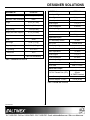
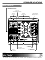
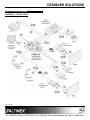
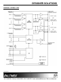
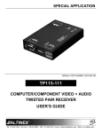
DESIGNER SOLUTIONS
MANUAL PART NUMBER: 400-0503-001
UT250-101
UNDER TABLE 8x4 VGA+AUDIO
MATRIX SWITCHER WITH
SHOW ME + RS-232 AUTO-SWITCHER
USER’S GUIDE
DESIGNER SOLUTIONS
TABLE OF CONTENTS
Page
PRECAUTIONS / SAFETY WARNINGS ............... 2
GENERAL..........................................................2
HANDLING ........................................................2
CLEANING.........................................................2
FCC NOTICE .....................................................2
ABOUT YOUR UT250-101...................................... 3
TECHNICAL SPECIFICATIONS............................. 4
PRODUCT DESCRIPTION ..................................... 6
APPLICATION DIAGRAMS .................................... 7
DIAGRAM 1: TYPICAL SETUP ..........................7
DIAGRAM 2: INTERNAL VIEW ..........................8
DIAGRAM 3: DIMENSIONS ...............................9
DIAGRAM 4: CABLE SUPPORT ......................10
DIAGRAM 5: INSTALLATION...........................11
DIAGRAM 6: OUTPUT SELECT WIRING.........12
INSTALLING YOUR UT250-101 ......................... 13
OPERATION........................................................... 13
MANUAL CONTROL ........................................13
RS-232 CONTROL...........................................14
DESCRIPTION OF COMMANDS .....................14
SUMMARY OF COMMANDS ...........................19
TROUBLESHOOTING GUIDE ............................. 19
POWER LEDS ARE OFF .................................19
NO DISPLAY....................................................19
NO RESPONSE ...............................................20
NO SOUND/SOUND TOO LOW .......................20
NO TWISTED PAIR OUTPUT ..........................20
ALTINEX POLICIES .............................................. 21
LIMITED WARRANTY/RETURN POLICIES .....21
CONTACT INFORMATION ..............................21
400-0503-001
1
DESIGNER SOLUTIONS
PRECAUTIONS / SAFETY WARNINGS
1.5 FCC NOTICE
1
•
Please read this manual carefully before using your
UT250-101 and keep it handy for future reference.
These safety instructions are to ensure the long life
of your UT250-101 and to prevent fire and shock
hazards. Please read them carefully and heed all
warnings.
1.1 GENERAL
•
•
Qualified ALTINEX service personnel or its
authorized representatives must perform all
service.
1.2 HANDLING
•
Handle the UT250-101 carefully. Dropping or
jarring can damage the unit.
• To prevent fire or shock, do not expose this unit
to water or moisture. Do not place the
UT250-101 in direct sunlight, near heaters, or
heat-radiating appliances, or near any liquid.
Exposure to direct sunlight, smoke, or steam can
harm internal components.
• Never restrict the airflow through the vents.
• Do not pull any cables that are attached to the
UT250-101.
• Do not place heavy objects on top of the
UT250-101.
• If the UT250-101 is not used for an extended
period, disconnect the adapter from the wall to
avoid fire, shock, and loss of power.
1.4 CLEANING
•
Unplug the UT250-101 adapter before cleaning.
•
Clean only with a dry cloth. Never use strong
detergents or solvents such as alcohol or
thinner. Do not use a wet cloth or water to clean
the unit.
400-0503-001
•
2
This device complies with Part 15 of the FCC
Rules. Operation is subject to the following two
conditions: (1) This device may not cause
harmful interference, and (2) this device must
accept any interference received, including
interference that may cause undesired
operation.
This equipment has been tested and found to
comply with the limits for a Class A digital
device, pursuant to Part 15 of the FCC Rules.
These limits are designed to provide reasonable
protection against harmful interference when the
equipment is operated in a commercial
environment. This equipment generates, uses,
and can radiate radio frequency energy and if
not installed and used in accordance with
instructions found herein, may cause harmful
interference to radio communications. Operation
of this equipment in a residential area is likely to
cause harmful interference in which case the
user will be required to correct the interference
at his own expense.
Any changes or modifications to the unit not
expressly approved by ALTINEX, Inc. could void
the user’s authority to operate the equipment.
DESIGNER SOLUTIONS
2
In addition to standard video and audio outputs, the
UT250-101 also has a 4TP (4 Twisted Pair) output
for each video output. These 4TP outputs can be
used with a compatible Twisted Pair receiver, like
the TP115-111, to transmit the video and audio
signals over long distances to remote projectors or
other multimedia presentation systems.
The UT250-101 is an 8x4 Video+Audio Matrix
Switcher designed to be mounted under a table as
part of an integrated audiovisual system. The
UT250-101 provides great flexibility for routing
multimedia signals from a single, convenient
location. Under Table solutions are ideal for
situations where it is too expensive or impractical to
install equipment directly into the furniture.
The latest generation of Twisted Pair devices uses
an innovative, patented technology* developed by
ALTINEX. The new signal processing technology
allows transmitting and receiving fully equalized
computer video signals, stereo, and audio signals
over long distances.
ABOUT YOUR UT250-101
UT250-101
Under Table 8x4 VGA+Audio Matrix
Switcher with “Show Me” Keys+RS-232
Auto-Switcher
The UT250-101 accepts 8 computer/YPbPr video
inputs and 8 stereo inputs. The audio inputs accept
both left and right audio, and then combine them to
create a mono signal. The 4 video outputs function
as 2 independent dual outputs where any input can
be routed to 2 or all 4 of the video outputs. Each of
the 4 outputs can be switched independently using
RS-232 control. The audio output follows the last
switched input and delivers a balanced mono
output on both the left and right channels.
* US Patent 7,065,190
Input-to-output switching can be made from one or
all of the following methods: RS-232, contact
closures, auto-switching. RS-232 control is
accomplished from a computer or controller using
the RS-232 bus. Contact closures with LEDs
(“Show Me” keys) allow manual switching through
the Output Select Control inputs on the front of the
unit. These controls are designed for use with
momentary switches having built-in LEDs. Any
input can be switched to either, or both, of the dual
outputs and the LEDs show which connections are
active. The UT250-101 can also be configured for
auto-switching. In Auto-Switch mode, the
UT250-101 automatically switches to the lowest
number input with an active video signal applied.
Any selections made by a user from the Output
Select Control input override the Auto-Switch
feature.
400-0503-001
3
DESIGNER SOLUTIONS
TECHNICAL SPECIFICATIONS
3
Specifications are subject to change.
See www.altinex.com for up-to-date information.
FEATURES/
DESCRIPTION
VGA:
UT250-101
Recommended Max.
Cable Lengths for
ALTINEX cable
Note: Measurements
made using ALTINEX
low-skew cable,
CB3150PV.
Input Connectors
Computer Video
Stereo Audio (mono out)
Power (use one only)
15-pin HD female (8)
3.5 mm female (8)
2-pin terminal block (1)
and 2.5 mm jack (1)
VGA:
Recommended Max.
Cable Lengths for
GENERIC cable
Note: Measurements
made using medium
GENERIC unshielded
twisted pair cable.
Output Connectors
Computer Video
Mono Audio
Twisted Pair
Video + Audio
15-pin HD female (4)
5-pin terminal block (1)
RJ-45 female (4)
TP Receivers
Control Connectors
RS-232
5-pin terminal block (1)
Output Select
5-pin terminal block (8)
640x480@60Hz
900 ft (274 m)
XGA:
1024x768@60Hz
700 ft (213 m)
SXGA: 1280x1024@60Hz
650 ft (198 m)
UXGA: 1600x1200@60Hz
600 ft (183 m)
640x480@60Hz
450 ft (137 m)
XGA:
1024x768@60Hz
350 ft (107 m)
SXGA: 1280x1024@60Hz
325 ft (99 m)
UXGA: 1600x1200@60Hz
300 ft (91 m)
TP115-111, MT115-111
Accessories Included
Power Adapter
115 VAC Power Cord
(PC5301US)
Compatibility
+12 VDC, 3.0 A
Supply
Equip.
: NEMA 5-15P
: IEC60320-C13
Signal Types
RGBHV, RGBS, RGsB
RS-232 Cable
DB9 F to terminal block
Video Signal
Resolutions
VGA through UXGA
480p through 1080p
Bottom Cover
Cable support
Miscellaneous
Hardware
Continued...
- mounting screws
- cable ties
- cable clamps
- term. block connectors
Table 1. UT250-101 General
400-0503-001
4
DESIGNER SOLUTIONS
MECHANICAL
ELECTRICAL
UT250-101
Minimum Table Thickness
0.5 in (13 mm)
Maximum Table Thickness
None
UT250-101
Video Input Signal
Video Signal
1.2 Vp-p max
Video Impedance
75 ohms
SYNC Signal
TTL (+/-)
8.1 in (206 mm)
SYNC Impedance
10 kohms
Height (body)
1.3 in (33 mm)
Audio Input Signal
Height (with cable support)
6.1 in (154 mm)
Length
9.9 in (251 mm)
Width
Material
Level
Aluminum
Finish
2.8 lb (1.27 kg)
Shipping Weight
3.3 lb (1.50 kg)
T° Operating
10°C-35°C
T° Maximum
50°C
10 kohms
1.0 Vp-p max
Output Select (I/O)
Silver
Net Weight
Humidity
Impedance
In = Momentary Switch
Out = LED
to GND
Internal Driver
Video Output Signal
Video Gain
90% non-condensing
Table 2. UT250-101 Mechanical
0dB +/- 0.5 dB
Video Impedance
75 ohms
SYNC Signal
TTL (+/-)
SYNC Impedance
22 ohms
Audio Output Signal
Impedance
50 ohms
Audio Gain
0dB +/- 0.5 dB
Twisted Pair Output
CAT-5/6 Twisted Pair (UTP)
Video/Sync/Audio
Signals
ALTINEX Standard
Power Consumption
External Adapter: 12 VDC
Table 3. UT250-101 Electrical
400-0503-001
5
1.66 A (20 W)
DESIGNER SOLUTIONS
PRODUCT DESCRIPTION
4
OUTPUT SELECT CONTROLS
5-PIN TERMINAL BLOCK (8)
AUDIO OUT
5-PIN TERMINAL BLOCK (1)
AUDIO IN
3.5 mm F (8)
VIDEO IN
15-PIN HD F (8)
DC POWER
2-PIN TB or DC JACK
VIDEO OUT
15-PIN HD F (4)
TWISTED PAIR OUT
RJ-45 HD F (4)
RS-232
5-PIN TB (1)
400-0503-001
CABLE SUPPORT
MOUNTING PINS (4)
6
DESIGNER SOLUTIONS
APPLICATION DIAGRAMS
5
DIAGRAM 1: TYPICAL SETUP
400-0503-001
7
DESIGNER SOLUTIONS
DIAGRAM 2: INTERNAL VIEW
400-0503-001
8
DESIGNER SOLUTIONS
DIAGRAM 3: DIMENSIONS
9.9"
[251 mm]
8.1"
[206 mm]
1.2"
[29 mm]
400-0503-001
3.8"
[97 mm]
3.8"
[97 mm]
9
DESIGNER SOLUTIONS
DIAGRAM 4: CABLE SUPPORT
TABLETOP
1.3"
[33 mm]
6.1"
[154 mm]
400-0503-001
10
DESIGNER SOLUTIONS
DIAGRAM 5: INSTALLATION
TABLETOP
1
MOUNT TO UT250-101 TO
THE UNDERSIDE OF THE
TABLE USING THE 6
SCREWS PROVIDED
CABLE
SUPPORT
MOUNTING
PINS
TABLETOP
2
SPRING OPEN THE CABLE
SUPPORT TO ALLOW THE
MOUNTING HOLES TO GO
OVER THE CABLE SUPPORT
PINS
TABLETOP
3
400-0503-001
WHEN THE CABLE SUPPORT
MOUNTING HOLES ARE
ALIGNED OVER THE
MOUNTING PINS ALLOW THE
SUPPORT TO SPRING BACK
11
DESIGNER SOLUTIONS
DIAGRAM 6: OUTPUT SELECT WIRING
400-0503-001
12
DESIGNER SOLUTIONS
INSTALLING YOUR UT250-101
6
OPERATION
Step 1. Decide how the UT250-101 will be
controlled: using contact closures on the
Output Select Controls, through computer
control using the RS-232 input, using
auto-switching, or all 3 methods.
7.1 MANUAL CONTROL
7.1.1 OUTPUT SELECT CONTROLS
The Output Select Control inputs on the front of
the UT250-101 allow 8 users direct control of
video switching. In this method, each user
typically has a control panel with 2 illuminated
switches along with video and audio inputs.
(See Diagram 6 for details and wiring
information.)
If using the Output Select Controls, see
Diagram 6 for wiring information.
Step 2. Locate the best position for the
UT250-101, but do NOT mount it to the
surface until all the cables are prepared.
When a user presses a control switch, the video
and audio from that control panel are displayed
at the output of the UT250-101. Each switch
connects its corresponding input to 2 outputs,
either 1A/1B, or 2A/2B. Once the connection is
made, the LED for that switch turns on. If the
switch’s LED is on and the switch is pressed,
the output is disabled and the LED turns off. The
audio output follows the last video input
selected.
Step 3. Prepare the mating cables using
high-quality cables for best results and
durability. Make sure the cables are long
enough to allow for a service-loop and so
the cables can be neatly routed beneath
the table to their destinations.
Step 4. Secure the unit under the table using the
screws provided with the unit.
Step 5. Make all necessary connections to the
UT250-101.
7.1.2 AUTO-SWITCH MODE
In
Auto-Switch
mode,
the
UT250-101
automatically switches to the lowest input
number with an active signal applied. For
example, if there is a signal on Input 4 and a
new signal is applied to Input 2, the outputs
defined with the Auto-Switch command will
switch to Input 2.
Step 6. When making connections to the terminal
blocks (audio out, control, RS-232, etc.),
use 24-28 AWG stranded wire for best
results. Also, use multi-conductor cable
where possible. For example, a standard
4-conductor cable works well for the
RS-232 connection.
The Output Select Control inputs override
Auto-Switch mode. When a user selects an
input using an external switch, the UT250-101
automatically switches to the selected input.
Step 7. Use the cable clamps provided to secure
the cables to the bottom of the table/desk.
Do NOT bend the cables too sharply
Step 8. Attach the cable support to the
UT250-101 as shown in Diagram 5. This
will help alleviate the strain of the cables
pulling from the connectors and protect
the cables from being accidentally pulled
free or damaged.
In Auto-Switch mode, Input 8 is designed for use
as a logo input that displays when the system is
not in use. If Auto-Switch mode is enabled then
overridden by the Output Select Control inputs,
when all active inputs are removed from
Inputs 1-7,
the
UT250-101
automatically
switches to Input 8.
Step 9. After power is applied to the UT250-101,
the unit is operational.
400-0503-001
7
Auto-Switch mode must be set using the
RS-232 input. See the AUTO commands in the
following section for details.
13
DESIGNER SOLUTIONS
7.2 RS-232 CONTROL
7.3 DESCRIPTION OF COMMANDS
The
UT250-101
has
many
advanced
remote-control capabilities accessible through
standard RS-232 communication. Control may be
accomplished through a computer, control system,
or any device capable of RS-232 communication.
Each command consists of a function name and
an optional unit ID. Unit IDs are required if 2 or
more UT250-101s are to be controlled
individually over the same RS-232 bus. The unit
ID can be changed using the [SID] and [RSI]
commands that are described later.
7.2.1 RS-232 INTERFACE
Example: [ONU2]
The control commands for the UT250-101, are
in a simple ASCII character format.
1.
ON
U2
Square brackets “[ ]” are part of the
command.
2.
Use uppercase letters for all commands.
3.
Spaces are not legal characters.
Unit ID “U0” does not need to be included at the
end of a command string.
Example:
Commands instruct the UT250-101 to perform
specific actions or request information. Some
commands do both simultaneously. A command
that instructs the UT250-101 only to perform an
action will generate feedback of “[ ]”. The open
bracket immediately followed by a closed
bracket indicates the card received a valid
command.
If the command requested
information, the feedback generated by the
UT250-101 is the acknowledgement of having
received a valid command. Invalid commands
generate feedback that includes “ERR” plus an
error code.
Example: [ERR001]
= Function
= Unit ID (only U2 executes ON)
[ON]:
Executed by U0
[ONU0]:
Executed by U0
NOTE:
Examples in this manual assume
the unit ID is U0 and do NOT
include the unit ID. If needed, the
unit ID for any unit can be specified
at the end of the command string as
shown above.
1. [STATUS]
This command displays the status of the unit.
Command Format: [STATUS]
Example:
Error number
Send the command [STATUS] to receive
feedback similar to the following:
Commands ending in “S” will be saved into
memory. Commands not ending in “S” will still
be executed, but will not be restored when the
system is reset or powered off, then on.
Note: Preset connections are
displayed as already executed, but
do not take effect until after the
[SW] switch command is executed.
OUT 1A - IN
OUT 1B - IN
OUT 2A - IN
OUT 2B - IN
AUDIO OUT AUTO_SWITCH
1 ON
1 ON
1 ON
1 ON
IN 1 ON
- OFF
If there is no card in slot 4, sending the [C4]
command will not return any feedback.
400-0503-001
14
DESIGNER SOLUTIONS
2. [CLR]
5. [ON]
This command resets the UT250-101 to the last
saved configuration.
This command turns on all outputs.
Command Format: [ON]
Command Format: [CLR]
Example:
Example:
Send [ON] to the UT250-101 and all 4 outputs
(1A, 1B, 2A, and 2B) will be enabled.
Clear the UT250-101 by sending [CLR]. Any
commands that were sent to the UT250-101
using the [...S] option will be recalled using this
command.
6. [OFFmX]
This command turns off one or more outputs.
Command Format: [OFFmX]
3. [VER]
This command displays the model number,
firmware version, and unit ID.
Command Format: [VER]
= Output No. (m = 1 or 2)
X
= Channel No. (X = A, B, or blank for both)
Example:
Example:
Turn off Output 1A by sending [OFF1A]. Outputs
1B, 2A, and 2B are unaffected.
Send the command [VER], and the UT250-101
will return feedback similar to the following:
Turn off Outputs 2A and 2B by sending [OFF2].
Outputs 1A and 1B are unaffected.
[UT250-101 690-0268-001 U0]
UT250-101
m
7. [OFF]
= the model number
690-0268-001 = the firmware version
This command turns off all outputs.
U0
Command Format: [OFF]
= the unit ID
Example:
4. [ONmX]
Send [OFF] to the UT250-101 and all 4 outputs
(1A, 1B, 2A, and 2B) will be disabled.
This command turns on one or more outputs.
Command Format: [ONmX]
m
= Output No. (m = 1 or 2)
X
= Channel No. (X = A, B, or blank for both)
8. [InOmX]
This command connects one input to one
output.
Example:
Command Format: [InOmX]
Turn on Output 1A by sending [ON1A] to the
UT250-101. Outputs 1B, 2A, and 2B are
unaffected.
Turn on Outputs 2A and 2B by sending [ON2] to
the UT250-101. Outputs 1A and 1B are
unaffected.
n
= Input No. (m = # from 1 to 8)
m
= Output No. (m = 1 or 2)
X
= Channel No. (X = A, B, or blank for both)
Example:
Connect Input 7 to Outputs 1A and 1B and then
Input 6 to Output 2A by sending the commands
[I7O1] and [I6O2A]. The first command connects
Input 7 to both channels of Output 1. The
second command connects Input 6 to Output 2
Channel A only.
400-0503-001
15
DESIGNER SOLUTIONS
9. [InO*]
Example:
Send the command [AUTO*] to the UT250-101.
If a video input signal is connected to any of the
inputs, that signal will be connected to all the
outputs. A valid video signal on Input 1 takes
precedence over Input 2, Input 2 over Input 3,
and so on.
This command connects one input to all outputs.
Command Format: [InO*]
n
= Input No. (m = # from 1 to 8)
Example:
Connect Input 1 to all outputs by sending [I1O*].
Input 1 is then connected to Outputs 1A, 1B, 2A,
and 2B.
13. [AUTO0]
This command disables auto-switching.
10. […P]
Example:
This command sets the path for switching the
outputs, but it is not active until the switch
command, [SW], is executed. Switching
commands ending in "P" are not executed
immediately. The path for outputs on multiple
units or the same unit can be preloaded.
Disable auto-switching mode by sending the
command [AUTO0].
14. [AUTO1]
This command enables auto-switching to
Output 1.
The
UT250-101
automatically
connects the lowest numbered input with an
active video signal to Outputs 1A and 1B.
Outputs 2A and 2B remain unchanged.
Auto-switching is automatically disabled when
an input is received on the Output Select Control
inputs.
Example:
See the example for the [SW] command that
follows.
11. [SW]
This command immediately connects inputs and
outputs previously set with the PATH command.
The command switches all paths set on one or
more units on the RS-232 bus.
Example:
Send the command [AUTO1] to the UT250-101.
If a video input signal is connected to any of the
inputs, that signal will be connected to Outputs
1A and 1B only. A valid video signal on Input 1
takes precedence over Input 2, Input 2 over
Input 3, and so on.
Example:
[I1O1AP]
Nothing is physically switched.
[I2O1BP]
Nothing is physically switched.
[SW]
Inputs 1 & 2 are switched
simultaneously.
15. [AUTO2]
This command enables auto-switching to
Output 2.
The
UT250-101
automatically
connects the lowest numbered input with an
active video signal Outputs: 2A and 2B. Outputs
1A and 1B remain unchanged. Auto-switching is
automatically disabled when an input is received
on the Output Select Control inputs.
12. [AUTO*]
This command enables auto-switching to all
outputs. The UT250-101 automatically connects
the lowest numbered input with an active video
signal to all outputs: 1A, 1B, 2A, and 2B.
Auto-switching is automatically disabled when
an input is received on the Output Select Control
inputs.
400-0503-001
16
DESIGNER SOLUTIONS
Example:
UT250-101
= Model number
Send the command [AUTO2] to the UT250-101.
If a video input signal is connected to any of the
inputs, that signal will be connected to Outputs
2A and 2B only. A valid video signal on Input 1
takes precedence over Input 2, Input 2 over
Input 3, and so on.
VR690-0268-001
= Firmware version
MA1111
= Matrix connections
ON1111
= Output ON/OFF status
The I/O connections are read left to right
representing the four outputs (1A, 1B, 2A, 2B)
and the input to which each is connected. The
first digit shows the input number to which
Output 1A is connected. The second digit is for
Output 1B, and so on.
16. [HELP]
This command displays information available for
the UT250-101 interface commands.
Command Format: [HELP]
The ON/OFF status line is also read from left to
right as Outputs 1A, 1B, 2A, and 2B. A "1"
indicates the output is on and a "0" indicates the
output is off.
Example:
In order to display the RS-232 commands
available for the UT250-101, send the command
[HELP]. The commands along with a brief
description will be displayed.
18. [STA1]
This command enables automatic feedback.
The
command
affects all
units
with
auto-feedback
capability,
not
just
the
UT250-101. The default is STA0, off.
17. [?]
This command displays general information
about a unit and its status.
Command Format: [STA1]
Command Format: [?]
Example 1:
Example:
Command =
Feedback =
Send the command [?] to receive feedback
status similar to the following.
[(UT250-101U0)(VR690-0268-001U0)
(MA1111U0) (ON1111U0)]
The feedback is broken down as follows:
Example 2:
Command =
Feedback =
(UT250-101U0)
(VR690-0268-001U0)
(MA1111U0)
(ON1111U0)
All status feedback is enclosed in brackets, “[ ]“.
Each data field within the status is enclosed in
parentheses. The first two characters identify
the status type. The last two characters are the
unit’s ID.
[OFF]
(ON0000U0)
ON = Output ON/OFF status
0000 = Out 1-4 = OFF
U0 = Unit ID is U0
[ON1A]
(ON1000U0)
ON = Output ON/OFF status
1000 = Out 1=ON, 2-4=OFF
U0 = Unit ID is U0
19. [STA0]
This command disables automatic feedback.
The
command
affects all
units
with
auto-feedback
capability,
not
just
the
UT250-101. The default is STA0, OFF.
Command Format: [STA0]
400-0503-001
17
DESIGNER SOLUTIONS
20. [...S]
22. [SIDn]
This command sets the UT250-101 to a new
unit ID. When assigning multiple IDs to several
units, connect only one unit at a time to the
RS-232 bus.
This command saves the configuration
command being sent in memory. Send the
command [I1O*S] to switch IN 1 to all outputs
and save the setting. After power-up or [CLR],
IN 1 will be connected to all outputs.
Command Format: [SIDn]
21. [AFB]
n
This command enables/disables the command
acknowledgement feedback, “[ ]”, from the
UT250-101. This setting is automatically saved
to memory and can only be changed by sending
the [AFB] command a second time. Use this
command when sending a large number of
commands with no delays, or when repeatedly
sending commands with no delays.
Example:
There are two UT250-101 units on the RS-232
bus, but they need to be controlled individually.
Connect only the first unit to the bus and then
send [SID1]. This unit is now U1. Disconnect the
first unit and connect the second unit. Now send
[SID2] to the second unit. The second unit is
now U2.
Command Format: [AFBm]
m
23. [RSI]
= 1 for ON, 0 for OFF
This command resets the unit ID to U0.
Example:
Command Format: [RSI]
Send 16 commands to the UT250-101 to
initialize the card. The required commands are
as follows:
Example:
Send the command [RSI] to reset unit ID U1
assigned above back to U0.
[I1O1A],
[I2O1B],
etc.
Send the [AFB] command first, and then the
switching commands.
[AFB0],
[I1O1A],
[I2O1B],
etc.
[AFB1]
In the above example, the brackets, “[ ]”, will not
be displayed after each command is executed.
400-0503-001
= Unit ID (n = # from 1 to 9)
18
DESIGNER SOLUTIONS
7.4. SUMMARY OF COMMANDS
1)
[STATUS]
Display card status
2)
[CLR]
Reset card to defaults
3)
[VER]
Display firmware version
4)
[ONmX]
Turn ON single output
5)
[ON]
Turn ON all outputs
6)
[OFFmX]
Turn OFF single output
7)
[OFF]
Turn OFF all outputs
8)
[InOmX]
Connect to one output
9)
[InO*]
Connect to all outputs
TROUBLESHOOTING GUIDE
8
We have carefully tested and found no problems in
the supplied UT250-101; however, we would like to
offer suggestions for the following:
8.1 POWER LEDS ARE OFF
Cause 1:
The unit is not plugged in.
Solution:
Make sure the power adapter is
plugged into a working AC outlet
and that the adapter’s DC end is
plugged all the way into the
UT250-101. If both LEDs are still not
ON, see Cause 2.
10) [...P]
Sets the path, [SW] preload
Cause 2:
The unit has a problem.
11) [SW]
Switch preloaded outputs
Solution:
12) [AUTO*]
Auto-switch: ON, all outputs
13) [AUTO0]
Auto-switch: OFF
If one power LED is on, but the other
is not then the UT250-101 may have
a problem. Please call ALTINEX at
(714) 990-2300.
14) [AUTO1]
Auto-switch: ON, Out #1
15) [AUTO2]
Auto-switch: ON, Out #2
Cause 1:
The source has a problem.
16) [HELP]
Display available commands
Solution:
17) [?]
Display system information
18) [STA1]
Auto-feedback on
19) [STA0]
Auto-feedback off
Check the source and make sure
that there is a signal present and all
source connections are correct. If
the source is working and there is
still no display, see Cause 2.
20) [...S]
Save current setting
Cause 2:
The output is not selected.
21) [AFB]
Enable/disable “[ ]”
Solution:
22) [SIDn]
Set all Card IDs
23) [RSI]
Reset Card IDs to defaults
Verify the connection status of the
UT250-101. (See RS-232 accessible
commands in Section 7.) If no
display is present, see Cause 3.
Cause 3:
Cable connections are incorrect.
Solution:
Make sure that cables are properly
connected. Also, make sure that the
continuity and wiring are good. If
there is still no display present, see
Cause 4.
Cause 4:
The display has a problem.
Solution:
Make sure the display is powered
and turned on. If there is still no
display, please call ALTINEX at
(714) 990-2300.
400-0503-001
8.2 NO DISPLAY
19
DESIGNER SOLUTIONS
8.3 NO RESPONSE
Cause 2:
The wrong output is selected.
Cause 1:
The unit is not recognized.
Solution:
Solution:
Reset the unit by turning the system
power off and then on again. Send
the [STATUS] command to see if
there is communication with the unit.
If there is no feedback, see Cause 2.
Check the status of the unit using
the RS-232 commands in section 7.
Verify the correct input-to-output
connection is selected and enabled.
If no sound is present, see Cause 3.
Cause 3:
Cable connections are incorrect.
Cause 2:
Unit is disconnected from RS-232.
Solution:
Solution:
Check the RS-232 connection to the
unit. Make sure the terminal block
connector is pushed all the way in
and that all the wires are connected.
If the unit is still not recognized, see
Cause 3.
Make sure that cables are
connected properly. Also, make sure
that the continuity and wiring are
good. If there is still no sound
present, see Cause 4.
Cause 4:
Destination
problem.
Cause 3:
Communication settings are bad.
Flow......... None
Data Bits..... 8
Parity ....... None
Solution 3: If the video output is working and
only the audio is missing, there may
be a problem with the UT250-101,
call ALTINEX at (714) 990-2300.
Solution 2: Verify the correct port is selected in
the
communications
software:
COM1, COM2, etc. If there is still a
problem, please call ALTINEX at
(714) 990-2300.
8.5 NO TWISTED PAIR OUTPUT
8.4 NO SOUND/SOUND TOO LOW
The source has a problem.
Solution:
Check the source and make sure
that it is working at an appropriate
volume level and all source
connections are correct. If the
source is working and there is still
no sound, see Cause 2.
400-0503-001
a
Solution 2: Set the volume of the destination
amplifier to a reasonable level. If
there is still no sound, see
Solution 3.
Stop Bits..... 1
Cause 1:
has
Solution 1: Make sure that the destination
amplifier is powered. If there is still
no sound, see Solution 2
Solution 1: Verify the communication software
settings. The UT250-101 default
settings are as follows:
Baud Rate .. 9600
amplifier
20
Cause 1:
The output is not selected.
Solution:
The TP output is the same as the
VGA output. Verify the connection
status of the UT250-101. (See
RS-232 accessible commands in
Section 7.) If no display is present at
the TP receiver, see Cause 2.
Cause 2:
No input signal applied.
Solution:
Make sure that the selected input
has a valid image applied. Connect
a local monitor to the VGA output of
the UT250-101 that corresponds to
the TP output. If an image is
present, there may be a problem
with the UT250-101. Call ALTINEX
at (714) 990-2300.
DESIGNER SOLUTIONS
ALTINEX POLICIES
9
9.1 LIMITED WARRANTY/RETURN POLICIES
Please see the ALTINEX website at
www.altinex.com for details on warranty and
return policies.
9.2 CONTACT INFORMATION
ALTINEX, Inc.
592 Apollo Street
Brea, CA 92821 USA
TEL: 714 990-2300
TOLL FREE: 1-800-ALTINEX
WEB: www.altinex.com
E-MAIL: [email protected]
400-0503-001
21