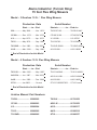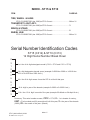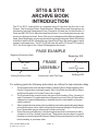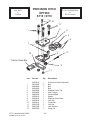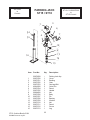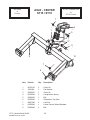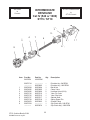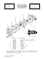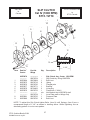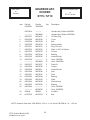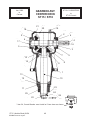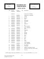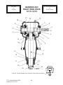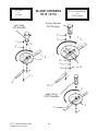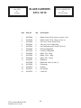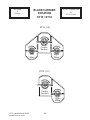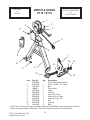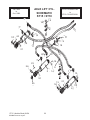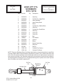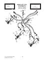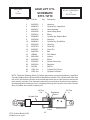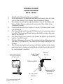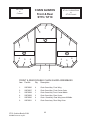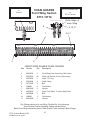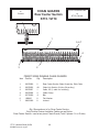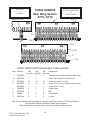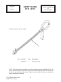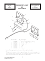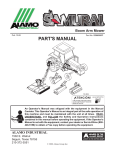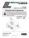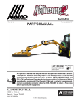
1
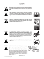
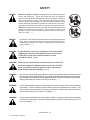
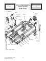
ST15 & ST10 Stingray
ARCHIVE BOOK
15 ' Flex Wing - 4 Gearbox Model
S/N ST15-C31200557203 (Jan. 2002 )
to
S/N ST15-Current
COMPLETE PARTS
LISTING
Archive Book
Part No.
02980337
2004 Edition Rev 01-09
ALAMO INDUSTRIAL
1502 E. Walnut
Seguin, Texas 78155
830-372-3551
© 2004 Alamo Group Inc.
Alamo Industrial (Terrain King)
15 foot Flex Wing Mowers
Model - 3 Gearbox 15 ft. / Flex Wing Mowers
Production Date
Start.........to.... End
Serial Number
Start s/n...............to..... End s/n
530................ May 1968.......... Nov. 1973*
TK530-07195..................TK530-21446*
CP180........... Dec. 1973......... Mar. 1976*
CP180-31188................. CP180-34724*
X-3................ Apr. 1975.......... Apr. 1978*
X-3-33388.......................X-3-36782*
TK15.............May 1978.......... Sep. 1982*
TK15-36783....................TK15-39979*
TK15HD........Oct. 1982..........May 1987*
TK15HD-39980...............TK15HD-46051*
A315..............Mar. 1990..........Sep. 1990*
A315-01001.................... A315-10080*
* End of Production for this Model
Model - 4 Gearbox 15 ft. Flex Wing Mowers
Production Date
Start.........to.... End
Serial Number
Start s/n...............to..... End s/n
TK15-IV........ Mar. 1985..........May. 1987*
TK15-IV-42840............... TK15-IV-46051*
AG15-IV........ Jun. 1987.......... Mar. 2002*
AG15-IV-01001............... AG15-IV-04643*
A415..............Jun. 1990.......... Dec. 2002*
A415-01001.................... A415-14000*
ST15............. Jan 2002........... Current
ST15-C31200557203..... ST15-Current
* End of Production for this Model
Archive Manual Part Numbers
TK530........................ 02980262
TK15-IV.........................00761652
CP180........................ 02980263
AG15-IV........................ 00761652
X-3.............................. 02980264
A315.............................. 02980317
TK15.......................... 02980265
A415.............................. 02980316
TK 15HD.....................02980265
ST15..............................02980337
INDEX - ST15 & ST10
ITEM
PAGE NO.
AXLE ASY.
Center Axle:
ST15-C31200557203 (Jan. 2002) to ST15-Current.................................... 26
Wing Axle
ST15-C31200557203 (Jan. 2002) to ST15-Current.................................... 18, 19
BLADE CARRIERS & BLADES:
ST15-C31200557203 (Jan. 2002) to ST15-Current.................................... 48, 49, 50
CHAIN GUARDS:
Front:
ST15-C31200557203 (Jan. 2002) to ST15-Current.................................... 64 thru 69
Rear:
ST15-C31200557203 (Jan. 2002) to ST15-Current.................................... 64 thru 69
COUNTER WEIGHT: (10 foot Model)
ST15-C31300557203 (Jan. 2002) to ST15-Current.................................... 20
CONTROL / LEVEL LIFT ROD:
ST15-C31200557203 (Jan. 2002) to ST15-Current.................................... 27
DECK COMPONENT:
Center Section:
ST15-C31200557203 (Jan. 2002) to ST15-C31200789311 (Oct. 2003).... 14, 15
ST15-C31200790311 (Nov. 2003) to ST15-Current....................................16, 17
Wing Section:
ST15-C31200557203 (Jan. 2002) to ST15-Current.................................... 18, 19
Skirt Assembly ST10:
ST15-C31300557203 (Jan. 2002) to ST15-Current.................................... 20, 21
DRIVELINE ASY:
PTO, Cat 5 C/V:
ST15-C31200557203 (Jan. 2002) to ST15-Current................................... 32, 33
INTERMEDIATE:
ST15-C31200557203 (Jan. 2002) to ST15-Current.................................... 35
WING:
ST15-C31200557203 (Jan. 2002) to ST15-Currentt................................... 34
SLIP CLUTCH:
Intermediate Driveline & Wing Driveleine:
ST15-C31200557203 (Jan. 2002) to ST15-Current.................................... 36, 37
GEARBOX ASY:
Divider:
ST15-C31200557203 (Jan. 2002) to ST15-Current.................................... 38, 39
Center:
ST15-C31200557203 (Jan. 2002) to ST15-Current.................................... 40, 41
Right & Right Wing:
ST15-C31200557203 (Jan. 2002) to ST15-Current.................................... 42 thru 45
ST15 (Archive Book) 01/04
©
2004 Alamo Group Inc.
Index - 3
INDEX - ST15 & ST10
ITEM
PAGE NO.
GEARBOX SHIELDS
ST15-C31200557203 (Jan. 2002) to ST15-Current..................................... 46, 47
HITCH ASY (OPTIONAL PRECISION HITCH)
ST15-C31200557203 (Jan. 2002) to ST15-Current..................................... 24
HYDRAULICS
Schematic - Axle Lift Cylinders
ST15-C31200557203 (Jan. 2002) to ST15-C31200789311 (Oct. 2003)..... 52, 53
ST15-C31200790311 (Nov. 2003) to ST15-Current.....................................54, 55
Schematic - Wing Lift & Fold Cylinders
ST15-C31200557203 (Jan. 2002) to ST15-C31200789311 (Oct. 2003)..... 58
ST15-C31200790311 (Nov. 2003) to ST15-Current.....................................59
Schematic - Control Valve:
ST15-C31200557203 (Jan. 2002) to ST15-Current..................................... 62
Wing Lift Cyl:
ST15-C31200557203 (Jan. 2002) to ST15-C31200789311 (Oct. 2003)..... 60
ST15-C31200790311 (Nov. 2003) to ST15-Current.....................................61
Axle Lift Cyl:
ST15-C31200557203 (Jan. 2002) to ST15-C31200789311 (Oct. 2003)..... 56
ST15-C31200790311 (Nov. 2003) to ST15-Current.....................................57
Attachments:
Axle Lift:
ST15-C31200557203 (Jan. 2002) to ST15-Current..................................... 18, 63
Wing Lift:
ST15-C31200557203 (Jan. 2002) to ST15-Current..................................... 18, 63
Valve Mnt:
ST15-C31200557203 (Jan. 2002) to ST15-Current..................................... 62
INDEX / INTRODUCTION
Index ............................................................................................................ 3 thru 5
Introduction................................................................................................... 6 & 13
PARKING JACK
ST15-C31200557203 (Jan. 2002) to ST15-Current..................................... 25
SAFETY CHAIN
Safety Chain................................................................................................. 70
SAFETY SECTION
Safety Section...............................................................................................7 thru 12
SKID SHOES
ST15-C31200557203 (Jan. 2002) to ST15-Current..................................... 16 thru 20
TONGUE:
Tongue:
ST15-C31200557203 (Jan. 2002) to ST15-Current..................................... 22, 23
Precision Hitch: (Optional)
ST15-C31200557203 (Jan. 2002) to ST15-Current..................................... 24
ST15 (Archive Book) 01/04
©
2004 Alamo Group Inc.
Index - 4
INDEX - ST15 & ST10
ITEM
PAGE NO.
TIRE, WHEEL & HUBS
ST15-C31200557203 (Jan. 2002) to ST15-Current..................................... 28 thru 31
TRANSPORT LIGHT ASY:
ST15-C31200557203 (Jan. 2002) to ST15-Current..................................... 71
WINCH & STAND
ST15-C31200557203 (Jan. 2002) to ST15-Current..................................... 51
WHEEL HUB
ST15-C31200557203 (Jan. 2002) to ST15-Current..................................... 28 thru 31
Serial Number Identification Codes
ST15 (C312) & ST10 (C313)
12 Digit Serial Number Break Down
C
3
1
2
0
0
5
5
7
2
0
3
1 st. thru 4 th. digits designate model (C312 = ST15 and C313 = ST10)
5 th. digit designates decade years (example 0=2000 thru 2009 or 1=2010 thru
2019 or 2=2020 thru 2029 & etc.)
6 th. thru 9 th. digit means it was the 557 th unit built that year
10 th. digit is year of the decade (example 2=2002 or 3=2003 & etc.)
11th. thru 12 th. digit is month of the year (example 03=March or 04=April & etc.)
0 = 1 st. decade of century,
0557 = Five hundred and fifty seventh unit built this year, 2 = the year of the decade
(2002), 03 = the month of the year (March)
Summary: This serial number means,
ST15 (Archive Book) 01/04
©
2004 Alamo Group Inc.
C312
Index - 5
= ST15,
ST15 & ST10
ARCHIVE BOOK
INTRODUCTION
The ST15 / ST10 Archive Book is a complete listing of Parts from the first Unit to the
Present. The Production Dates, Serial Numbers, Special Notes and Descriptions are
furnished to help find Replacement Parts. Dimension (if listed) are for Identification of
Parts and MAY NOT be to Manufacturing Specification, Your measurements may vary
some from dimensions listed. Some Parts may be changed and be different than parts
listed. Some Modification may be required when replacing older parts. Match S/N's listed
in this Book with the S/N's listed at the top of each Parts Page. See Index page for serial
number code break down. The ST15 S/N will start with prefix C312 and ST10 prefix is
C313, the first 4 digits of the 12 digit S/N designates the model.
PAGE EXAMPLE
Beginning Production Date
Dec. 2002
to
Current
Ending Production Date
Beginning S/N
FRAME
ASSEMBLY
Componets Listed This Page
S/N ST15-C31200557203
to
S/N ST15-Current
Ending S/N
For ordering parts the following instructions are offered to help eliminate delay
1.
2.
3.
4.
The purchase order must include the Name, Address (Ship to Street Address) of the
Person / Organization ordering the parts. Who / How Parts should be Billed. Name
and Phone Number of a Contact Person at your end.
The Purchase Order must list clearly the correct Part Number of Part. Quantity of
each Part wanted, Complete and correct Description of each Part. All Parts will be
shipped as requested depending on availability and/or reasonability of request
carrier / method.
Alamo Industrial reserves the right to substitute parts where applicable and change
prices Without prior notice. Alamo Industrial also reserves the right to Ship Parts the
most Reasonable way as determined by Alamo Industrial.
Some Parts are unlisted items, which are special production items not normally
stocked or built for a limited / special use, These parts may be subject to special
handling or cannot be priced till ordered. Always Request a quotation for such Parts
before sending a purchase order.
ST15 (Archive Book) 01/04
©
2004 Alamo Group Inc.
Index - 6
SAFETY
SECTION
© 2004 Alamo Group Inc.
Safety Section - 7
SAFETY
Read these assembly instructions through completely and understand them
before proceeding with the assembly of the equipement.
A safe and careful operator is the best operator. Safety is of primary importance to the manufacturer and should be to the owner/operator. Most accidents can be avoided by being aware of
your equipment, your surroundings, and observing certain precautions. The first section of this
manual includes a list of Safety Messages that, if followed, will help protect the operator and
bystanders from injury or death. Read and understand these Safety Messages before assembling, operating or servicing this Implement. This equipment should only be operated by those
persons who have read the Manual, who are responsible and trained, and who know how to do
so safely and responsibly.
The Safety Alert Symbol combined with a Signal Word, as seen below, is used throughout this
manual and on decals which are attached to the equipment. The Safety Alert Symbol means:
“ATTENTION! BECOME ALERT! YOUR SAFETY IS INVOLVED!” The Symbol and Signal
Word are intended to warn the owner/operator of impending hazards and the degree of possible
injury faced when operating this equipment..
Practice all usual and customary safe working precautions and
above all---remember safety is up to YOU. Only YOU can prevent
serious injury or death from unsafe practices.
CAUTION!
The lowest level of Safety Message; warns of possible injury. Decals
located on the Equipment with this Signal Word are Black and Yellow.
WARNING!
Serious injury or possible death! Decals are Black and Orange.
DANGER!
Imminent death/critical injury. Decals are Red and White. (SG-1)
Safety Section - 8
© 2004 Alamo Group Inc.
SAFETY
PELIGRO!
Si no lee Ingles, pida ayuda a alguien que si lo lea para que le
traduzca las medidas de seguridad. (SG-3)
!LEA EL INSTRUCTIVO!
READ, UNDERSTAND, and FOLLOW the following Safety
Messages. Serious injury or death may occur unless care is
taken to follow the warnings and instructions stated in the Safety
Messages. Always use good common sense to avoid hazards.
(SG-2)
Si no lee Ingles, pida ayuda a alguien que
si lo lea para que le traduzca las medidas
de seguridad. (SG-3)
!
PELIGRO!
LEA EL
INSTRUCTIVO!
WARNING!
Perform service, repairs and lubrication according to the maintenance section. Ensure the unit
is properly lubricated as specified in the lubrication schedule and all bolts and nuts are properly
torqued. Failure to properly service, repair and maintain this Implement in good operating
condition could cause component failure and possible serious injury or even death. (SG-35)
WARNING!
Operate this Equipment only with a Tractor equipped with an
approved roll-over-protective system (ROPS). Always wear seat
belts. Serious injury or even death could result from falling off the
tractor--particularly during a turnover when the operator could be
pinned under the ROPS. (SG-7)
DANGER!
Never work under the Implement, the framework, or any lifted component unless the Implement is securely supported or blocked up to
prevent sudden or inadvertent falling which could cause serious injury
or even death. (SG-14)
WARNING!
Use caution and wear protective gloves when handling sharp objects such as blades, knives,
and other cutting edges. Be alert to worn component surfaces which have sharp edges. Sharp
surfaces can inflict severe laceration injuries if proper hand protection is not worn. (SG-37)
Safety Section - 9
© 2004Alamo Group Inc.
SAFETY
WARNING!
Many of the parts are heavy and require lifting assistance. Do not try to
lift the heavy parts by yourself. Get help from another employee or from
an overhead crane.
WARNING!
The operator and all support personnel should wear hard hats,
safety shoes, safety glasses, and proper hearing protection at all
times for protection from injury including injury from items thrown by
the equipment. (SG-16)
WARNING!
Always wear safety shoes with steel toes when working on this equipment.
It is recommended that the safety shoes have metatarsal guards.
WARNING!
When welding use Welding hood with the appropriate OSHA required
protective lens, welding apron, and welding gloves.
DANGER!
Always disconnect the wire leads from the mower valve solenoid before
performing service on the Tractor or Mower. Use caution when working
on the Tractor or Mower. Tractor engine must be stopped before
working on Mower or Tractor. The Mower Blades could inadvertently be
turned on without warning and cause immediate dismemberment, injury
or death. (SBM-12)
DANGER!
Never run the tractor engine in a closed building or without adequate
ventilation. The exhaust fumes can be hazardous to your health.
(SG-23)
Safety Section - 10
© 2004 Alamo Group Inc.
SAFETY
DANGER!
Before starting the mower make sure the area is clear and the floor has
been swept. The mower blade can throw objects several hundred feet.
Thrown objects could damge property or cause severe bodily injuries even
death.
WARNING!
Make certain that the “Slow Moving Vehicle” (SMV) sign is installed in
such a way as to be clearly visible and legible. When transporting the
Equipment use the Tractor flashing warning lights and follow all local traffic
regulations. (SG-6)
DANGER!
Start tractor only when properly seated in the Tractor seat. Starting a
tractor in gear can result in injury or death. Read the Tractor operators
manual for proper starting instructions. (SG-13)
DANGER!
Do not operate this Equipment with hydraulic oil leaking. Oil is
expensive and its presence could present a hazard. Do not check for
leaks with your hand! Use a piece of heavy paper or cardboard. Highpressure oil streams from breaks in the line could penetrate the skin
and cause tissue damage including gangrene. If oil does penetrate the
skin, have the injury treated immediately by a physician knowledgeable and skilled in this procedure. (SG-15)
WARNING!
Always read carefully and comply fully with the manufacturers instructions when handling oil, solvents, cleansers, and any other chemical
agent. (SG-22)
DANGER!
All Safety Shields, Guards and Safety devices including
(but not limited to) - the Deflectors, Chain Guards, Steel
Guards, Gearbox Shields, PTO integral shields , and
Retractable Door Shields should be used and maintained in good working condition. All safety devices
should be inspected carefully at least daily for missing
or broken components. Missing, broken, or worn items
must be replaced at once to reduce the possibility of
injury or death from thrown objects, entanglement, or
blade contact. (SGM-3)
Safety Section - 11
© 2004Alamo Group Inc.
SAFETY
DANGER!
NEVER use drugs or alcohol immediately before or while operating the
Tractor and Implement. Drugs and alcohol will affect an operator’s
alertness and coordination and therefore affect the operator’s ability to
operate the equipment safely. Before operating the Tractor or Implement, an operator on prescription or over-the-counter medication must
consult a medical professional regarding any side effects of the medication that would hinder their ability to operate the Equipment safely.
NEVER knowingly allow anyone to operate this equipment when their
alertness or coordination is impaired. Serious injury or death to the
operator or others could result if the operator is under the influence of
drugs or alcohol. (SG-27)
DANGER!
Operate the Tractor and/or Implement controls only while properly seated
in the Tractor seat with the seat belt securely fastened around you.
Inadvertent movement of the Tractor or Implement may cause serious
injury or death. (SG-29)
WARNING!
Engine Exhaust, some of its constituents, and certain vehicle
components contain or emit chemicals known to the state of
California to cause cancer and birth defects or other
reproductive harm. (SG-30)
WARNING!
Battery posts, terminals and related accessories contain lead
and lead compounds, chemicals known to the state of California to cause cancer and birth defects or other reproductive
harm. Wash Hands after handling. (SG-31)
WARNING!
Use extreme caution when getting onto the Implement to perform repairs, maintenance and
when removing accumulated material. Only stand on solid flat surfaces to ensure good footing.
Use a ladder or raised stand to access high spots which cannot be reached from gound level.
Slipping and falling can cause serious injury or death. (SG-33)
WARNING!
Avoid contact with hot surfaces including hydraulic oil tanks, pumps, motors, valves and hose
connections. Relieve hydraulic pressure before performing maintenance or repairs. Use
gloves and eye protection when servicing hot components. Contact with a hot surface or fluid
can cause serious injury from burns or scalding. (SG-34)
WARNING!
Avoid contact with hot surfaces of the engine or muffler. Use gloves and eye protection when
servicing hot components. Contact with a hot surface or fluid can cause serious injury from
burns or scalding. (SG-38)
Safety Section - 12
© 2004 Alamo Group Inc.
ST15 / ST10
Flex Wing Rotary
ARCHIVE BOOK
ST15 Archive Book
This is a complete listing of Parts from the first Unit to the Present (or end of model
production). The Production Dates, Serial Numbers, Special Notes and Descriptions are
furnished to help find Replacement Parts. Dimension (if listed) are for Identification of Parts
and MAY NOT be to Manufacturing Specification, Your measurements may vary some
from dimensions listed. Some Parts may be changed and be different than parts listed.
Some Modification may be required when replacing older parts. Match S/N' and Ship
Dates if available.
ID The ST15 (Jan 2002 to
Current)
The ST10 & ST15 was built from Jan. 2002 (s/n ST15-C31200557203) to Current (s/nSTCurrent) .
Serial Numbers:
See The Index Pages for an explanation on of how to identify your unit by the 12 digit serial number
code, The Serial number code shows manufacturing production date of your unit.
Gearboxes:
The best way to ID the ST10 & ST15 (Stingray Model) is by the Gearboxes, This is a 4 Gearbox
Model (Divider and Center Blade Gearbox two separate gearboxes). The Divider gearbox has a 1-3/
8" X 21 Spline Output Shafts. The Blade Gearbox (Center & Wings) has a long section of the Housing
that protrudes below where it bolts to the deck. The Blade Gearbox has a Dip-Stick type top Plug. The
Blade Carrier Retaining Nut used a Cone Shaped Washer which no other model has to this time.
Blade Carriers:
The Blade Carriers are a Round Shaped Pan Weldment. The Blade Bolts are a Shouldered Blade
Bolt, and a bushing is used with the Blade Bolt. This was not the only 4 gearbox model that had a Shoulder
Blade Bolt but is the only model to use a bushing with the Shoulder Bolt.
Driveline Options:
There were no Driveline size options, There was a Cat IV (4) Wing Drivelines and a Cat V (5)
PTO Driveline used on this model. Some parts will not interchange between drivelines. See Part numbers
for interchangeable parts.
Axles:
The axles are Independent from center to wings. The type Hydraulic Axle lift is a Phasing (Slave)
Cylinder system, the Hydraulic lift of the mower is done by using 3 hydraulic Cylinders mounted one in
the center and one on each wing. The Cylinders are connected together into one Hydraulic flow in series.
ST15 (Archive Book) 01/04
© 2004 Alamo Group Inc.
13
DECK COMPONENTS
Center Section
ST15 / ST10
Jan. 2002
to
Oct. 2003
37,38,39
ST15-C31200557203
to
ST15-C31200789311
32,33
34,35
2,5,6
21,24,25,
26,40,41
3,4,31
9,21,22
20,23
23,36
27
4,7,8
28,29,30
9
10,11,12,13,14,15,
18
17
10,12,13,14,15,16
ST15 (Archive Book) 01/04
© 2004 Alamo Group Inc.
14
19
25
2,4,5,6
DECK COMPONENTS
Center Section
ST15 / ST10
Jan. 2002
to
Oct. 2003
ST15-C31200557203
to
ST15-C31200789311
Item
Part No.
Qty.
Description
1
2
3
4
5
6
7
8
9
10
11
12
13
14
15
16
17
18
19
02978500
02978501
00755082
000944
00008300
15B1200
02978502
02975147
02978503
02891800
02978504
15B800
00001800
15B1600
01408S
02978505
02959332
02978506
02978507
02978508
02978509
02957042
15B600
02978510
02978511
00015800
00753642
00037200
02978512
00012101
10180500
02978513
02978971
10180500
02978915
02978514
02978968
00753753
02978515
02978516
00024100
10058000
02962363
02978638
1
2
6
16
2
2
2
4
2
2
1
3
3
3
3
2
2
1
1
1
2
4
4
3
1
8
2
2
1
2
2
1
1
2
1
1
1
4
1
1
2
2
2
1
Center Section Asy
Hose Organizer
Bolt
Lock Nut
Bolt
Flat Washer
Skid Mount Asy
Bolt
Wing Lift Spacer Plate
Bolt
Retainer Pin, Long Center Pin
Flat Washer
Lock Nut
Flat Washer
Roll Pin
Retainer Pin, Outer Pins
Bolt
Cylinder Lug Adj. Asy.
Spacer Plate
Spacer Plate
Wing Lock Pin,
Bolt
Flat Washer
Lynch Pin
Slow Moving Vehicle Sign Stand
Lock Nut
Bolt
Lock Nut
Bolt Access Cover Plate
Lock Washer
Bolt
Gearbox Asy, CW, 540 RPM
Gearbox Asy, CW, 1000 RPM
Bolt
SMV Sign
Gearbox Asy, Divider, 540 RPM
Gearbox Asy, Divider,1000 RPM
Bolt
Transport Lock Pin
Operator / Parts Manual Box
Flat Washer
Bolt
Lock Nut
Hose Clamp
20
21
22
23
24
25
26
27
28
29
30
31
32
33
34
35
36
37
38
39
40
41
ST15 (Archive Book) 01/04
© 2004 Alamo Group Inc.
15
DECK COMPONENTS
Center Section
ST15 / ST10
Nov. 2003
to
Current
37,38,39
ST15-C31200790311
to
ST15-Current
32,33
34,35
2,5,6
21,24,25,
26,40,41
3,4,31
9,21,22
20,23
23,36
27
4,7,8
28,29,30
9
10,11,12,13,14,15,
18
17
10,12,13,14,15,16
ST15 (Archive Book) 01/04
© 2004 Alamo Group Inc.
16
19
25
2,4,5,6
DECK COMPONENTS
Center Section
ST15 / ST10
Nov. 2003
to
Current
ST15-C31200790311
to
ST15-Current
Item
Part No.
Qty.
Description
1
2
3
4
5
6
7
8
9
10
11
12
13
14
15
16
17
02978500
02978501
00755082
000944
00008300
15B1200
02978502
02975147
02978503
02891800
02978504
15B800
00001800
15B1600
01408S
02978505
03200369
02959332
02978506
02978507
02978508
02978509
02957042
15B600
02978510
02980471
00015800
00753642
00037200
02978512
00012101
10180500
02978513
02978971
10180500
03200347
02978514
02978968
00753753
02978515
02978516
00024100
10058000
02962363
02978638
1
2
6
16
2
2
2
4
2
2
1
3
3
3
3
2
2
2
1
1
1
2
4
4
3
1
8
2
2
1
2
2
1
1
2
1
1
1
4
1
1
2
2
2
1
Center Section Asy
Hose Organizer
Bolt
Lock Nut
Bolt
Flat Washer
Skid Mount Asy
Bolt
Wing Lift Spacer Plate
Bolt
Retainer Pin, Long Center Pin
Flat Washer
Lock Nut
Flat Washer
Roll Pin
Retainer Pin, Outer Pins
Bolt, (Light Truck Tire)
Bolt, (Laminated & Aircraft Tire)
Cylinder Lug Adj. Asy.
Spacer Plate, (Light Truck Tire)
Spacer Plate, (Laminated & Aircraft Tire)
Wing Lock Pin,
Bolt
Flat Washer
Lynch Pin
Slow Moving Vehicle Sign Stand
Lock Nut
Bolt
Lock Nut
Bolt Access Cover Plate
Lock Washer
Bolt
Gearbox Asy, CW, 540 RPM
Gearbox Asy, CW, 1000 RPM
Bolt
SMV Sign
Gearbox Asy, Divider, 540 RPM
Gearbox Asy, Divider,1000 RPM
Bolt
Transport Lock Pin
Operator / Parts Manual Box
Flat Washer
Bolt
Lock Nut
Hose Clamp
18
19
20
21
22
23
24
25
26
27
28
29
30
31
32
33
34
35
36
37
38
39
40
41
ST15 (Archive Book) 01/04
© 2004 Alamo Group Inc.
17
DECK COMPONENTS
Wing Section
ST15 / ST10
Jan. 2002
to
Current
17
ST15-C31200557203
to
ST15-Current
18 38
16
11
1
8 9
7
12
13
20 14
17
19 37
18
17
10
35
9
2
3
2
8
3
36
32
33
8
7
7
4 5
21 22
25
26
28
24 36
8
2
6
22
15
30
31
29
ST15 (Archive Book) 01/04
© 2004 Alamo Group Inc.
18
28
23
27
Jan. 2002
to
Current
Item
Part No.
R-Wing
DECK COMPONENTS
Wing Section
ST15 / ST10
Part No.
L-Wing
Qty.
1
ST15-C31200557203
to
ST15-Current
Description
02978517
------------1
Wing Asy, R-Wing (Shown)
------------02978532
1
Wing Asy, L-Wing (Not Shown
2
02978518
02978518
4
Hinge Pin
3
02978519
02978519
2
Hinge Spacer Tube
4
00749017
00749017
8
Lock Nut
5
10121000
10121000
8
Bolt
6
02978520
02978520
1
Hinge Spacer Tube
7
01408S
01408S
5
Roll Pin
8
15B1600
15B1600
6
Flat washer
9
02978521
02978521
2
Pin
10
02978522
02978522
2
Floating lug
11
000944
000944
6
Lock Nut
12
00755082
00755082
6
Bolt
13
02978523
------------1
Gearbox, CCW R-Wing
-----------02978533
1
Gearbox, CW L-Wing
14
2A381312
2A381312
3
Plow Bolt
16
02978525
02978525
1
Skid Shoe, L or R Wing
17
00001800
00001800
10
Lock Nut
18
15B800
15B800
10
Flat Washer
19
02978795
02978795
1
Lock Washer
20
331212C
331212C
2
Half Nut
21
02978526
02978526
1
Retainer Pin
22
02892000
02892000
1
Bolt
23
02978527
02978527
1
Clevis Pin
24
02959332
02959332
1
Bolt
25
02978528
02978528
1
Wheel Suspension Plate, Standard
26
00751035
00751035
1
Rubber Sandwich
27
02978529
02978529
1
Wing Wheel Standard Asy.
28
00037200
00037200
5
Lock Nut
29
03200269
03200269
2
Bolt
30
00755153
00755153
1
Cotter Pin
31
001291
001291
1
Grease Nipple, Self tap
32
02978512
02978512
1
Bolt Access Cover Plate
33
00012101
00012101
2
Lock Washer
34
10180500
10180500
2
Bolt
35
02978530
02978530
1
Wing Adj. Assy.
36
00011800
00011800
2
Bolt
37
02776600
02776600
6
Bolt
38
02978531
------------1
Adjustable Side Mount, R-Wing
------------02978534
1
Adjustable Side Mount, L-Wing
Note: Qty Shown above is for one Wing, double qty of parts for both wings w/ the exception
of items 1, 13 & 38 which must be used on a specific wing.
ST15 (Archive Book) 01/04
© 2004 Alamo Group Inc.
19
SKIRT ASY
ST10
Jan. 2002
to
Current
ST15-C31200557203
to
ST15-Current
1,3,7
2,3,7
8
4
14
5
10
1,3,7,11
19
12
13
9
3,7,15
16
21,23
17,18,20,22
ST15 (Archive Book) 01/04
© 2004 Alamo Group Inc.
20
SKIRT ASY
ST10
Jan. 2002
to
Current
ST15 (Archive Book) 01/04
© 2004 Alamo Group Inc.
ST15-C31200557203
to
ST15-Current
Item
Part No.
Qty.
Description
1
02891800
2
Bolt
2
3
02892000
15B800
2
9
Bolt
Flat washer
4
5
02978551
250-145
1
2
Chain guard, double
Bolt
7
8
00001800
02978552
9
1
Lock nut
Hinge pin
9
10
02030300
02978553
4
1
Lock nut
Skirt Assy, 10' Unit Only
11
12
02978554
02978555
1
2
Hinge pin
Counter weight
13
14
15B1600
00755305
4
2
Flat washer
Bolt
15
16
2A381312
02978556
5
1
Plow bolt,
Skirt skid
17
18
00015800
02978557
3
3
Lock nut
Chain, 11 links
19
20
02975147
15B600
4
3
Bolt
Flat washer
21
22
15B1200
00752675
4
3
Flat washer
Bolt
23
000944
4
Lock nut
21
TONGUE ASY.
ST15 / ST10
Jan. 2002
to
Current
15
ST15-C31200557203
to
ST15-Current
14
3
1
5
2
4
16
9
13
10
8
9
2
11
12
1
ST15 (Archive Book) 01/04
© 2004 Alamo Group Inc.
8
22
7
6
7
TONGUE ASY.
ST15 / ST10
Jan. 2002
to
Current
ST15-C31200557203
to
ST15-Current
Item
Part No.
Qty.
Description
1
15B1600
3
Flat Washer
2
3
01408S
02978536
3
1
Roll Pin
Hitch Clevis, Standard Clevis
4
5
02978537
02978538
1
1
Pivoting Hitch Asy.
Pivot Hitch Weld Sleeve
6
7
02891800
15B800
1
3
Bolt
Flat Washer
8
9
00001800
001291
3
6
Lock Nut
Grease Fitting
10
11
02978539
02978540
1
2
Hitch Frame Assy.
Retaining Pin
12
13
02892000
02978547
2
1
Bolt
Retaining Pin
14
15
02978548
02978549
1
1
PTO Storage Support
Bent Hitch Pin
16
02978550
1
Hitch Pin Clip
Note: Item # 3 is the standard Tongue Hitch Clevis , there is an Optional Hitch Clevis
offered called Precision Hitch Kit # 02978611. See Parts break down for this optional
hitch.
ST15 (Archive Book) 01/04
© 2004 Alamo Group Inc.
23
PRECISION HITCH
OPTION
ST15 / ST10
Jan. 2002
to
Current
ST15-C31200557203
to
ST15-Current
2, 12
3
4
1
6
5
6
7
13
8
10
Tractor Draw Bar
9
11
Iten
Part No.
Qty.
Description
1
2
3
4
5
6
7
8
9
10
11
12
13
02978611
00752405
02892000
02010800
02978608
02978609
00003500
02978610
02978612
02978796
02978613
00037200
00001300
00036900
-2
1
1
1
1
3
1
1
1
1
2
1
1
Precision Hitch Kit (Optional)
Bolt
Bolt
Bolt
Drawbar Clevis Top
Hitch Tongue
Grease Nipple
Spacer
Drawbar Clevis Base
Lock Nut
Clamp Bar
Lock Nut
Lock Washer
Cotter Pin
ST15 (Archive Book) 01/04
© 2004 Alamo Group Inc.
24
PARKING JACK
ST15 / ST10
Jan. 2002
to
Current
3
1
6
2
14
ST15-C31200557203
to
ST15-Current
7
4
15
8
5
10
9
11
16
12
13
Item
Part No.
Qty
Description
1
2
3
4
5
6
7
8
9
10
11
12
13
14
15
16
02979699
02979700
02979701
02979702
02979703
40010000
02979704
02979705
00024000
02979706
02979707
02979708
02979709
02979710
02979711
02979712
02979713
-1
2
2
2
2
1
1
1
1
1
1
1
2
1
1
1
Parking Jack Asy.
Cover
Bushing
Gear
Carriage Bolt
Cotter Pin
Dowel
Handle
Nut
Body
Pin
Bearing
Washer
Nut
Dowel
Screw
Leg
ST15 (Archive Book) 01/04
© 2004 Alamo Group Inc.
25
AXLE - CENTER
ST15 / ST10
Jan. 2002
to
Current
ST15-C31200557203
to
ST15-Current
7
6
1
5
4
2
3
8
12
7
9
Item
Part No.
Qty.
Description
1
2
00755153
15B1600
3
2
Cotter Pin
Flat Washer
3
4
02978527
02978542
1
2
Clevis Pin
Compression Spring
5
6
02959332
02978543
1
1
Bolt
Suspension Top Plate
7
8
00037200
02978546
5
1
Lock Nut
Center Section Wheel Standard
9
03200269
4
Bolt
ST15 (Archive Book) 01/04
© 2004 Alamo Group Inc.
26
CONTRL ROD
ST15 / ST10
Jan. 2002
to
Current
ST15-C31200557203
to
ST15-Current
1
2
2
3
4
7
6
1
2
5
8
2
Item
Part No.
Qty
Description
1
2
00755153
15B1600
3
13
Cotter Pin
Flat Washer
3
4
02978535
02978541
2
2
Clevis Pin
Lift Rod
5
6
02978544
00059500
2
2
Leveling Rod Lug
Nut
7
8
23511000
02978545
2
2
Half Nut
Clevis Pin
Note: Qty listed is for two control rods, left & Right side.
ST15 (Archive Book) 01/04
© 2004 Alamo Group Inc.
27
TIRES & WHEELS
ST15 / ST10
Jan. 2002
to
Current
1
23
2 3
20
ST15-C31200557203
to
ST15-Current
19
4 5
6
7
8
10
9
18
11
16
17
24
15
14
21
25
25
22
13
21
26
26
ST15 (Archive Book) 01/04
© 2004 Alamo Group Inc.
28
12
TIRES & WHEELS
ST15 / ST10
Jan. 2002
to
Current
ST15-C31200557203
to
ST15-Current
Item
Part No.
Qty.
Description
1
02978573
1
Spindle, w/ #9, 15, 16, Double End
1
2
02978574
02978575
1
1
Spindle, w/ #9, 15, 16, Single End
Seal
3
4
02978576
02978577
1
1
Bearing
Race
5
6
001291
02978578
1
1
Grease Fitting
Hub, w/ Bearing Cups
7
8
02978579
02978580
1
1
Race
Bearing
9
10
000163
02978930
1
1
Cotter Pin
Wheel 15”
11
12
02978931
02978932
1
1
Valve Stem
Tire
13
14
00749171
02978581
5
1
Wheel Bolt
Dust Cap
15
16
5E12160
02978582
1
1
Castle Nut
Machine Bushing
17
18
10180500
02978797
5
1
Bolt
Tire, Solid Laminated, Complete
19
20
00012101
00013901
5
5
Lockwasher
Nut
21
22
02978798
02978799
2
1
Wheel Half, 6 x 9, 5 Bolt
Tire, Solid Laminated, 6 x 9
23
23
02978583
02978584
1
1
Hub, Includes #2-8 & 14
1
Bearing Kit, Includes #2, 3, 4, 7, 8, 14, 16
24
02978800
02978801
1
Aircraft Tire 22 x 6.6 x 10 Complete
Tube & Liner For #02978800
25
26
00001300
00749171
5
5
Lockwasher
Bolt
ST15 (Archive Book) 01/04
© 2004 Alamo Group Inc.
29
Jan. 2002
to
Current
TIRES & WHEELS
ST15 / ST10
ST15-C31200557203
to
ST15-Current
WHEEL ATTACHMENT
Laminated Tire and Wheels:
Attach the wheels to the hubs. If puncture-proof, Laminated Tires and Wheels are used,
be sure the flat side of the nut is against the Wheel. Tighten wheel bolts to 85 ft/lbs. Note
direction of travel and curvature of rubber segments in tire and install as shown below to
give longest tire life.
Direction of travel
Note Segment
Curvature
Place Flat Side of Lug
Nut against Wheel
Segmented Tire
ST15 (Archive Book) 01/04
© 2004 Alamo Group Inc.
30
TIRES & WHEELS
ST15 / ST10
Jan. 2002
to
Current
ST15-C31200557203
to
ST15-Current
Adjust the Spindle for Trailing Width,
Adjust Center axle Spindles for Width:
When the Spindles a re installed and mower is being readied for use. The Spindles in the
Center Axle need to be adjusted to give the desired trailing width, this determines where
the Wheels runn inline with the mower and the wheel track width. this will need to be done
once and should not change unless it is unbolted and moved.
ST15 (Archive Book) 01/04
© 2004 Alamo Group Inc.
31
PTO DRIVELINE
540 RPM Cat V
ST15 / ST10
Jan. 2002
to
Current
14,15
16
6,9
8
3
7
ST15-C31200557203
to
ST15-Current
12
5
4
10
25
26 18
1,2
22
21
19
1,2
13
11
20
27
23
24
17
28
Item Part No.
1
2
3
4
5
6
7
8
9
10
11
12
13
02978692
02978663
02978664
02978665
02978666
02978667
02978668
02978669
02978670
02978671
02978672
02978673
02978674
02978675
02978676
Qty. Description
Item Part No.
Qty. Description
1
3
2
1
1
1
1
1
1
1
1
1
1
1
1
14
15
16
17
18
19
20
21
22
23
24
25
26
27
28
1
2
1
1
1
1
1
1
1
6
1
1
6
1
1
Driveline Asy. (540)
Grease Fitting
Universal Joint
Double Yoke
Shield support
Grease Fitting
Yoke, w/ QD Collar
Yoke & Sleeve Asy.
Shaft Asy, Outer
QD Collar Kit, Plastic
QD Collar Kit, Steel
Shaft, Splined
Roll Pin
Yoke, Inner
Universal Joint
02978677
02978678
02978679
02978680
02978681
02978682
02978683
02978684
02978685
02978709
02978687
02978688
02978689
02978690
02978691
Yoke
Bolt & Nut
Male Shaft Asy.
Cone Asy.
Bearing
Retaining Collar
Outer Cone
Shield, Outer
Shield, Inner
Bolt, Wing D/L
Inner Cone
Retaining Collar
Screw
Safety Chain
Shield Asy, Complete
NOTE: This is a Cat 5 Driveline used on 540 RPM Model and Some parts will not interchange
wth the Cat 4 used on the 1000 RPM Model. Check part numbers for intrchangable parts.
ST15 (Archive Book) 01/04
© 2004 Alamo Group Inc.
32
PTO DRIVELINE
1000 RPM Cat IV
ST15 / ST10
Jan. 2002
to
Current
14,15
16
6,9
8
3
7
ST15-C31200557203
to
ST15-Current
12
5
4
10
25
1,2
26 18
22
21
19
1,2
13
11
20
27
23
24
17
28
Item Part No.
1
2
3
4
5
6
7
8
9
10
11
12
13
02978949
02978663
02978950
02978951
02978952
02978667
02978953
02978954
02978955
02978671
02978672
02978956
02978957
02978958
02978696
Qty. Description
Item Part No.
Qty. Description
1
3
2
1
1
1
1
1
1
1
1
1
1
1
1
14
15
16
17
18
19
20
21
22
23
24
25
26
27
28
1
2
1
1
1
1
1
1
1
6
1
1
6
1
1
Driveline Asy. (1000)
Grease Fitting
Universal Joint
Double Yoke
Shield support
Grease Fitting
Yoke, w/ QD Collar
Yoke & Sleeve Asy.
Shaft Asy, Outer
QD Collar Kit, Plastic
QD Collar Kit, Steel
Shaft, Splined
Roll Pin
Yoke, Inner
Universal Joint
02978959
02978678
02978960
02978961
02978962
02978707
02978963
02978964
02978965
02978709
02978966
02978713
02978689
02978690
02978967
Yoke
Bolt & Nut
Male Shaft Asy.
Cone Asy.
Bearing
Retaining Collar
Outer Cone
Shield, Outer
Shield, Inner
Bolt, Wing D/L
Inner Cone
Retaining Collar
Screw
Safety Chain
Shield Asy, Complete
NOTE: This is a Cat 4 Driveline used on 1000 RPM Model and Some parts will not interchange
wth the Cat 5 used on the 540 RPM Model. Check part numbers for intrchangable parts.
ST15 (Archive Book) 01/04
© 2004 Alamo Group Inc.
33
WING DRIVELINE
Cat IV (540 or 1000)
ST15 / ST10
Jan. 2002
to
Current
ST15-C31200557203
to
ST15-Current
2
5
1
12
10
9
5
4
6
14
7
11
15
8
20
18
3
22
17
19
21
16
Item
Part No.
Qty. Description
Item
Part No.
Qty. Description
1.
02978693
02978705
1
1
2.
02978706
1
3
4
5
6
7
8
9
10
02978694
02978695
02978696
02978697
02978698
02978699
02978700
02978701
4
1
2
1
1
1
1
1
11
12
13
14
15
16
17
18
19
20
21
22
02978702
02978703
02978667
02978704
02978663
02978707
02978708
02978709
02978710
02978711
02978712
02678713
1
1
1
1
2
1
1
6
1
1
1
1
ST15 (Archive Book) 01/04
© 2004 Alamo Group Inc.
Driveline Asy. Wing
Driveline Half Asy.
Clamp Yoke End
Driveline Half Asy,
Clutch End
Bolt & Nut
Cllamp Yoke
Universal Joint
Yoke, Outer
Roll pin
Shield Support
Tube, Outer
Tube, Inner
34
Roll Pin
Yoke, Inner
Grease Fitting
Clutch Asy
Grease Fitting
Retaining Collar
Outer Cone
Bolt
Shield Asy, Outer
Shield Asy, Inner
Clutch Cone
Retaining Collar
INTERMEDIATE
DRIVELINE
Cat IV (540 or 1000)
ST15 / ST10
Jan. 2002
to
Current
ST15-C31200557203
to
ST15-Current
3
5
4
7
3
6
2
8
9
Item
1
2
3
4
5
6
7
8
9
Part No.
540 RPM
Part No.
1000 RPM
Qty.
Description
02978714
------------02978694
02978695
02978696
02978716
02978715
02978717
02978718
02978663
02978704
------------
-------------02978993
02978694
02978695
02978696
02978716
02978715
02978717
02978718
02978663
------------02978974
--1
1
2
1
1
1
1
2
1
1
Driveline Asy, 540 RPM
Driveline Asy, 1000 RPM
Bolt & Nut
Clamp Yoke
Universal Joint (X-Kit)
Yoke, Pin Yoke
Yoke, Slip Yoke
Splined shaft
Spring Dowel Pin
Grease Fitting
Slip Clutch Asy, 540 RPM
Slip Clutch Asy, 1000 RPM
ST15 (Archive Book) 01/04
© 2004 Alamo Group Inc.
35
1
SLIP CLUTCH
Cat IV (540 RPM)
ST15 / ST10
Jan. 2002
to
Current
ST15-C31200557203
to
ST15-Current
3
10
5
6
7
2
8
4
1
9
9
1234
1234
1234
1234
1234
1234
1234
1234
1234
1234
1234
1234
1234
2
123
123
123
123
123
123
123
123
123
1-1/4"
Iten
Part No.
Qty.
Description
1
2
3
4
5
6
7
8
9
02978704
02978694
02978719
02978720
02978721
00754202
02978723
02978724
02978725
02978726
1
8
1
1
2
1
1
1
8
Clutch Asy, Center or Wing 540 RPM
Bolt & nut
Spring
Flanged yoke
Bushing
Lining ring
Flange hub, 1 3/8x21
Inner plate
Pressure plate
Bolt & nut
NOTE: To adjust this Slip Clutch tighten Bolts, (item 9) untill Springs, (item 2) are a
compressed length of 1-1/4" as shown in drawing above. When tightening use an
alternating pattern in a cris-cross pattern.
ST15 (Archive Book) 01/04
© 2004 Alamo Group Inc.
36
SLIP CLUTCH
Cat IV (1000 RPM)
ST15 / ST10
Jan. 2002
to
Current
ST15-C31200557203
to
ST15-Current
3
10
5
6
7
2
8
4
2
1
9
9
Item
1
2
3
4
5
6
7
8
9
1234
1234
1234
1234
1234
1234
1234
1234
1234
1234
1234
1234
1234
123
123
123
123
123
123
123
123
123
123
1-1/4"
Part No.
Center
Part No
Wings
Qty.
Description
02978974
-----------02978694
02978975
02978976
02978977
02978978
02978979
------------------------02978991
02978980
------------02878704
02978694
02978719
02978720
02978771
00754202
02978723
-----------02978724
02978725
02978726
-1
8
1
1
2
1
n/a
1
1
8
Slip Clutch Asy, Center 1000 RPM
Slip Clutch Asy. Wing 1000 RPM
Bolt & nut
Spring
Flanged yoke
Bushing
Lining ring
Flange hub, 1 3/8x21
Not used on Asy # 02978974 at all
Inner Plate used on Wings Only
Pressure Plate
Bolt & nut
NOTE: To adjust this Slip Clutch tighten Bolts, (item 9) untill Springs, (item 2) are a
compressed length of 1-1/4" as shown in drawing above. When tightening use an
alternating pattern in a cris-cross pattern.
ST15 (Archive Book) 01/04
© 2004 Alamo Group Inc.
37
GEARBOX ASY.
DIVIDER
ST15 / ST10
Jan. 2002
to
Current
ST15-C31200557203
to
ST15-Current
3
2
1
4
5
6
6
24
23
21
7
20
15
16
1-3/8" X 21 Spline
17
22
7
8
8
9
9
10
10
11
11
12
12
9
9
13
13
17
19
16
18
ST15 (Archive Book) 01/04
© 2004 Alamo Group Inc.
38
15
14
GEARBOX ASY.
DIVIDER
ST15 / ST10
Jan. 2002
to
Current
Item
Part No.
Part No.
540 RPM
1000 RPM
02978514
------------1
2
ST15-C31200557203
to
ST15-Current
Qty.
Description
----------02978968
--
Gearbox Asy, Divider, 540 RPM
Gearbox Asy, Divider 1000 RPM
02978727
02978728
02978727
02978728
1
1
Oil Filler Plug,
Cover
3
4
02978729
02978730
02978729
02978730
6
6
Bolt
Spring washer
6
7
02978731
02978732
02978731
02978732
2
2
Plug, Oil Level
Shaft, 1-3/8" X 21 Spline
8
9
02978733
02978734
02978733
02978734
2
4
Oil seal
Bearing
10
12
02978735
02978736
-------------
02978735
------------02978969
2
2
2
Internal Circlip
Gear, 540 RPM
Gear, 1000 RPM
13
14
02978737
02978738
02978737
02978738
2
1
Shim Kit
Casing
15
16
02978739
02978740
0297839
02978740
2
2
Internal Circlip
Seal
17
18
02978741
02978742
02978741
02978742
2
1
Shim
Bearing
19
20
02978743
02978744
02978743
02978743
1
1
Shaft
Shoulder ring
21
22
02978742
02978746
02978742
-------------
1
1
Bearing
Gear, 540 RPM
23
------------000944
02978970
000944
1
4
Gear, 1000RPM
Lock Nut
24
00753753
00753753
4
Bolt
NOTE: Gearbox Gear ratio 1000 RPM is 1.35 in : 1 out and a 540 RPM is 1 in : 1.35 out.
ST15 (Archive Book) 01/04
© 2004 Alamo Group Inc.
39
GEARBOX ASY.
CENTER DECK
ST15 / ST10
Jan. 2002
to
Current
21
18
20
ST15-C31200557203
to
ST15-Current
19
2
2
6
6
17
4
16
5
3
14
8
9
1
13
10
12
23
11
24
25
26
22
* Item 24, Coned Washer must install w/ Cone down as shown
ST15 (Archive Book) 01/04
© 2004 Alamo Group Inc.
5
7
15
40
GEARBOX ASY.
CENTER DECK
ST15 / ST10
Jan. 2002
to
Current
Item
ST15-C31200557203
to
ST15-Current
Part No.
540 RPM
Part No.
1000 RPM
Qty
Description
02978513
------------
-
Gearbox Asy, 540 RPM
1
------------02978747
02978971
02978747
1
Gearbox Asy, 1000 RPM
Casing
2
3
02978748
02978733
02978748
02978733
2
1
Bearing
Seal
4
5
02978749
02978750
02978749
02978750
1
2
Shaft, Input
Snap Ring
6
7
02978751
02978752
02978751
02978752
2
1
Shim
Cotter Pin
8
9
02978753
02978754
02978753
-------------
1
1
Nut
Gear, 540 RPM
10
------------02978758
02978972
02978758
1
1
Gear, 1000 RPM
Shaft
11
12
02978755
02978756
02978755
02978756
1
1
Sealing lid
Seal
13
14
02978757
02978759
02978757
02978759
1
1
Bearing
Bearing
15
16
02978760
02978761
02978760
02978761
1
1
Shim
Shim
17
18
02978762
02978763
02978462
02978763
1
4
Cap
Bolt
19
20
02978764
02978765
02978764
02978765
1
1
Plug
Cover
21
02978766
-------------
-----------02978973
1
1
Gear, 540 RPM
Gear, 1000 RPM
22
23
02978571
02978569
02978571
02978569
1
1
Nut, Slotted
Flatwasher
24
25
02978769
02978770
02978769
02978770
1
1
Washer, Disc Spring (Coned)
Splined Hub (Ref Only - weld on part)
26
02978572
02978572
1
Cotter pin
NOTE: Gearbox Gear ratio 1000 RPM is 1.2 in : 1 out and a 540 RPM is 1 in : 1.5 out.
ST15 (Archive Book) 01/04
© 2004 Alamo Group Inc.
41
GEARBOX ASY.
RIGHT WING DECK
ST15 / ST10
Jan. 2002
to
Current
21
18
20
ST15-C31200557203
to
ST15-Current
19
2
2
6
6
17
4
16
5
3
14
8
9
1
13
10
12
23
11
24
25
26
22
* Item 24, Coned Washer must install w/ Cone down as shown
ST15 (Archive Book) 01/04
© 2004 Alamo Group Inc.
5
7
15
42
GEARBOX ASY.
RIGHT WING DECK
ST15 / ST10
Jan. 2002
to
Current
ST15-C31200557203
to
ST15-Current
Item
Part No.
Qty
Description
1
02978523
02978747
1
Gearbox Asy, 540 or 1000 RPM
Casing
2
3
02978748
02978733
2
1
Bearing
Seal
4
5
02978749
02978750
1
2
Shaft, Input
Snap Ring
6
7
02978751
02978752
2
1
Shim
Cotter Pin
8
9
02978753
02978772
1
1
Nut
Gear, 540 or 1000 RPM
10
11
02978758
02978755
1
1
Shaft
Sealing lid
12
13
02978756
02978757
1
1
Seal
Bearing
14
15
02978759
02978760
1
1
Bearing
Shim
16
17
02978761
02978762
1
1
Shim
Cap
18
19
02978763
02978764
4
1
Bolt
Plug
20
21
02978765
02978773
1
1
Cover
Gear, 540 or 1000 RPM
22
23
02978571
02978569
1
1
Nut, Slotted
Flatwasher
24
25
02978769
02978770
1
1
Washer, Disc Spring (Coned)
Splined Hub (Ref Only - weld on part)
26
02978572
1
Cotter pin
NOTE: Gearbox Gear ratio 540 or 1000 RPM is the same, 1 in : 1.35 out, the gear ratio
between the 540 & 1000 RPM output will be determined by the Gear ratio of the divider
Gearbox. Right and Left Wing Gearboxes use the same components, it is where the Input
gear (item 21) & Top Cover (item 20) is installed that makes them different.
ST15 (Archive Book) 01/04
© 2004 Alamo Group Inc.
43
GEARBOX ASY.
LEFT WING DECK
ST15 / ST10
Jan. 2002
to
Current
19
20
18
ST15-C31200557203
to
ST15-Current
21
2
2
6
6
17
4
5
3
16
15
14
8
9
1
13
10
12
23
11
24
25
26
22
* Item 24, Coned Washer must install w/ Cone down as shown
ST15 (Archive Book) 01/04
© 2004 Alamo Group Inc.
5
7
44
GEARBOX ASY.
LEFT WING DECK
ST15 / ST10
Jan. 2002
to
Current
Item
ST15-C31200557203
to
ST15-Current
Part No.
Qty
Description
02978533
-
Gearbox Asy, 540 or 1000 RPM
1
2
02978747
02978748
1
2
Casing
Bearing
3
4
02978733
02978749
1
1
Seal
Shaft, Input
5
6
02978750
02978751
2
2
Snap Ring
Shim
7
8
02978752
02978753
1
1
Cotter Pin
Nut
9
10
02978772
02978758
1
1
Gear, 540 or 1000 RPM
Shaft
11
12
02978755
02978756
1
1
Sealing lid
Seal
13
14
02978757
02978759
1
1
Bearing
Bearing
15
16
02978760
02978761
1
1
Shim
Shim
17
18
02978762
02978763
1
4
Cap
Bolt
19
20
02978764
02978765
1
1
Plug
Cover
21
22
02978773
02978571
1
1
Gear, 540 or 1000 RPM
Nut, Slotted
23
24
02978569
02978769
1
1
Flatwasher
Washer, Disc Spring (Coned)
25
26
02978770
02978572
1
1
Splined Hub (Ref Only - weld on part)
Cotter pin
NOTE: Gearbox Gear ratio 540 or 1000 RPM is the same, 1 in : 1.35 out, the gear ratio
between the 540 & 1000 RPM output will be determined by the Gear ratio of the divider
Gearbox. Right and Left Wing Gearboxes use the same components, it is where the Input
gear (item 21) & Top Cover (item 20) is installed that makes them different.
ST15 (Archive Book) 01/04
© 2004 Alamo Group Inc.
45
GEARBOX SHIELDS
ST15 / ST10
Jan. 2002
to
Current
ST15-C31200557203
to
ST15-Current
1
6
6
4
9
9
22
4
20
8
16
22
21
2
7
14
5
12
22 2
2
7
10
11
22
23
7
2
15
8
4
18
17
9
6
16
19
ST15 (Archive Book) 01/04
© 2004 Alamo Group Inc.
46
GEARBOX SHIELDS
ST15 / ST10
Jan. 2002
to
Current
ST15-C31200557203
to
ST15-Current
Item
Part No.
Qty.
Description
1
02978599
1
Center Section Shield Asy.
2
4
00011700
02978510
17
3
Lockwasher
Lynch Pin
5
6
02978600
02978601
1
3
Splitter Shield Mount
Shield Hinge Pin
7
8
02972026
02978602
15
2
Bolt
Splitter Shield Rest Bracket
9
10
40010000
02978514
6
1
Cotter Pin
Splitter Gearbox, 540 RPM
11
02978968
02978603
1
1
Splitter Gearbox, 1000 RPM
CenterGearbox Pivot Shield Mount
12
13
00015800
15B600
4
4
Lock Nut
Flatwasher
14
15
00059900
02978604
4
1
Bolt
Left Wing Gearbox Pivot Shield
16
17
02978605
02978606
2
1
Wing Gearbox Pivot Mount
Right Wing Gearbox Shield
18
02978513
02978971
1
1
540 RPM Gearbox, CW
1000 RPM Gearbox, CW
19
20
02978523
02978533
1
1
540 & 1000 RPM Gearbox, CCW
540 & 1000 RPM Gearbox, CW
21
22
00035900
00023500
2
17
Bolt
Flat washer
23
02978607
1
Shaft Cover Plastic, 10' Units Only
ST15 (Archive Book) 01/04
© 2004 Alamo Group Inc.
47
BLADE CARRIERS
ST15 / ST10
Jan. 2002
to
Current
ST15-C31200557203
to
ST15-Current
Center Section
CW Rotation
Left Wing
CW Rotation
7
7
1
6
3
2
6
8
4
12
13
14
5
15
11
8
10
2
Right Wing
CCW Rotation
9
ST15 (Archive Book) 01/04
© 2004 Alamo Group Inc.
48
4
BLADE CARRIERS
ST15 / ST10
Jan. 2002
to
Current
ST15-C31200557203
to
ST15-Current
Item
Part No.
Qty.
Description
1
2
02978558
02978559
1
2
Blade Carrier & Pan,Center, (w/ item 3 & 6)
Blade Carrier & Pan, Wing, (w/ item 4)
3
4
02978560
02978561
1
2
Pan Only, Center Section Only
Pan Only, Left or Right Wing
5
6
02978562
02978563
2
6
Pan Reinforcements, Center Pan Only
Bushing, Blade Bolt
7
8
02978796
02978564
6
2
Locknut, f/ Blade Bolt
Blade, CW - Wing
9
10
02978565
02978566
2
2
Blade, CCW - Wing
Blade, CW - Center
11
02978567
02978568
6
6
Blade Bolt
Blade Bolt & Nut ( w/ item 7)
12
13
02978569
02978570
3
3
Flatwasher
Washer
14
15
02978571
02978572
3
3
Nut, Slotted
Cotter Pin
ST15 (Archive Book) 01/04
© 2004 Alamo Group Inc.
49
Jan. 2002
to
Current
BLADE CARRIER
ROTATION
ST15 / ST10
ST15 (15')
Center
Section
Left
Wing
Right
Wing
ST10 (10')
Center
Section
Right
Wing
ST15 (Archive Book) 01/04
© 2004 Alamo Group Inc.
50
ST15-C31200557203
to
ST15-Current
WINCH & STAND
ST15 / ST10
Jan. 2002
to
Current
ST15-C31200557203
to
ST15-Current
1
2
5
3
11
4
5
8
7
15
10
14
14
6
9
12
Item
1
2
3
4
5
6
7
8
9
10
11
Part N0.
02978897
02978933
00753642
15B600
02978934
00015800
02978935
02978936
02978937
02776600
00001800
10180500
13
Qty
-1
3
3
1
5
1
1
1
4
4
2
Description
Winch & Stand Kit (Optional)
Winch, 1600 lb., 5.1:1 ratio
Bolt
Flat Washer
Cable
Lock Nut
Winch Lift Stand
Winch Lift Lug, Right
Winch Lift Lug, Left
Bolt
Lock Nut
Bolt
NOTE: Items 12 through 15 are not included in Winch Kit # 02978897, they are already on the Wing
Section of mower as part of Wing Axle. See Deck Components Section for these parts
ST15 (Archive Book) 01/04
© 2004 Alamo Group Inc.
51
AXLE LIFT CYL.
SCHEMATIC
ST15 / ST10
Jan. 2002
to
Oct. 2003
7
19
18
7
14
ST15-C31200557203
to
ST15-C31200789311
4
1
14
13
10
17
4
19
18
11
21
20
3
22
7
13
23
24
9
2
7
14
13
21
13
14
25
21
8
ST15 (Archive Book) 01/04
© 2004 Alamo Group Inc.
52
14
AXLE LIFT CYL.
SCHEMATIC
ST15 / ST10
Jan. 2002
to
Oct. 2003
ST15-C31200557203
to
ST15-C31200789311
Item
Part No.
Qty.
Description
1
02978633
1
Hose Asy.
2
3
02978636
02978637
1
1
Cylinder Asy. Large Bore
Hose Assembly
4
7
02978638
02978616
6
5
Hose Clamp, Metal
Elbow
8
9
02978639
02978640
1
1
Cylinder Asy. Medium Bore
Hose Asy.
10
11
02978641
02978642
1
1
Cylinder Asy. Small Bore
Hose Asy.
13
14
00755153
02978527
6
6
Cotter Pin
Clevis Pin
17
18
02957042
15B600
1
3
Bolt
Flat Washer
19
20
00015800
02978643
3
1
Locknut
Elbow
21
22
02978655
02978618
3
1
Stroke Control Asy.
Restrictor
23
24
262-004
C502-193
1
1
Roll Pin
Cylinder Pin (Center)
25
C502-194
1
Cylinder Pin Sleeve
NOTE: These are Phasing (Slave) Cylinders and must be connected as shown, Large Bore
Cylinder, Medium Bore Cylinder and then Small Bore Cylinder. The Cylinders will have to be
free of Air, this means cylinders must be bled and remain an air tight system to prevent air
from entering cylinders. See Operators manual for procedures to connect these cylinders.
See drawing below shownig how oil is bypassed through the Cylinder to the next Cylinder
when Cylinders are stroked completly out.
Oil Flow
Out
Rephasing
Groove
Cylinder Rod
Piston
ST15 (Archive Book) 01/04
© 2004 Alamo Group Inc.
53
Oil Flow
In
AXLE LIFT CYL.
SCHEMATIC
ST15 / ST10
Nov. 2003
to
Current
7
19
18
7
14
ST15-C31200790311
to
ST15-Current
4
1
14
13
10
17
4
19
18
11
21
20
3
22
7
13
23
24
9
2
7
14
13
21
13
14
25
21
8
ST15 (Archive Book) 01/04
© 2004 Alamo Group Inc.
54
14
AXLE LIFT CYL.
SCHEMATIC
ST15 / ST10
Nov. 2003
to
Current
ST15-C31200790311
to
ST15-Current
Item
Part No.
Qty.
Description
1
2
02978633
02980479
1
1
Hose Asy.
Cylinder Asy. Large Bore
3
4
02978637
02978638
1
6
Hose Assembly
Hose Clamp, Metal
7
8
02978616
02980480
5
1
Elbow
Cylinder Asy. Medium Bore
9
10
02978640
02980481
1
1
Hose Asy.
Cylinder Asy. Small Bore
11
13
02978642
00755153
1
6
Hose Asy.
Cotter Pin
14
17
02978527
02957042
6
1
Clevis Pin
Bolt
18
19
15B600
00015800
3
3
Flat Washer
Locknut
20
21
02978643
02978655
1
3
Elbow
Stroke Control Asy.
22
23
02978618
262-004
1
1
Restrictor
Roll Pin
24
25
C502-193
C502-194
1
1
Cylinder Pin (Center)
Cylinder Pin Sleeve
NOTE: These are Phasing (Slave) Cylinders and must be connected as shown, Large Bore
Cylinder, Medium Bore Cylinder and then Small Bore Cylinder. The Cylinders will have to be
free of Air, this means cylinders must be bled and remain an air tight system to prevent air
from entering cylinders. See Operators manual for procedures to connect these cylinders.
See drawing below shownig how oil is bypassed through the Cylinder to the next Cylinder
when Cylinders are stroked completly out.
Oil Flow
Out
Rephasing
Groove
Cylinder Rod
Piston
ST15 (Archive Book) 01/04
© 2004 Alamo Group Inc.
55
Oil Flow
In
AXLE LIFT CYL.
ST15 / ST10
Jan. 2002
to
Oct. 2003
ST15-C31200557203
to
ST15-C31200789311
1
9
3
4
10
10
10
2
10
10
8
10
7
5
6
Item
Part No.
L-Wing
Part No.
R-Wing
Part No.
Center
Qty
Description
1.
02978641
------------------------02978650
02978652
02978653
02978654
02957042
00015800
02978655
02030300
02978656
-----------02978657
-----------02978657
02978659
02978653
02978654
02957042
00015800
02978655
02030300
02978689
-----------------------02978660
02978661
02978662
02978653
02978654
02957042
00015800
02978655
02030300
02978990
1
1
1
1
1
1
1
1
1
1
1
1
Cyl. Asy. 3" Bore X 5" Stroke
Cyl. Asy. 3-1/4" Bore X 5" Stroke
Cyl. Asy. 3-1/2" Bore X 5" Stroke
Cyl. Barrell
Piston
Rod
Rod Clevis
Bolt
Locknut
Stroke Control Asy.
Locknut
Seal Kit
2.
3.
4.
5.
6.
7.
8.
9.
10.
NOTE: These are Phasing Cylinders and must be connected in the correct
order to work correctly. Seal Kit components not available as single parts.
ST15 (Archive Book) 01/04
© 2004 Alamo Group Inc.
56
AXLE LIFT CYL.
ST15 / ST10
Nov. 2003
to
Current
ST15-C31200790311
to
ST15-Current
5
6
3
1
2
12
11
4
10
9
8
7
Item
1.
2.
3.
4.
5.
6.
7.
8.
9.
10.
11.
12.
Part No.
L-Wing
Part No.
R-Wing
Part No.
Center
Qty
Description
02980481
------------------------02980482
02980476
02980483
02980484
02980485
02980475
02980486
02978655
02980487
00750940
00016200
02980488
-----------02980480
-----------02980489
02980476
02980490
02980491
02980492
02980493
02980486
02978655
02980487
00750940
00016200
02980488
-----------------------02980479
02980494
02980476
02980495
02980496
02980497
02980498
02980486
02978655
02980487
00750940
00016200
02980488
1
1
1
1
1
1
1
1
1
1
1
1
1
1
1
Cyl. Asy. 3" Bore X 5" Stroke
Cyl. Asy. 3-1/4" Bore X 5" Stroke
Cyl. Asy. 3-1/2" Bore X 5" Stroke
Cyl. Barrell
Piston Nut
Piiston
Wear Ring
Seal Kit
Gland
Rod
Stroke Control Asy.
Jam Nut
Nut
Bolt
Clevis End
ST15 (Archive Book) 01/04
© 2004 Alamo Group Inc.
57
HYD SCHEMATIC
WING LIFT CYL.
ST15 / ST10
Jan. 2002
to
Nov. 2003
ST15-C31200557203
to
ST15-C312007890311
4
3
4
5
2
1
8
7
2
7
3
5
8
6
1
Item
Part No.
Qty
Description
1
2
3
4
5
6
7
8
02978614
02978615
02978616
02978617
02978618
02978527
00755153
15B1600
2
2
2
2
2
2
2
2
Cylinder Asy. 3" Bore x 12" Stroke
Breather, Filter
Elbow
Hose Asy.
Restrictor
Clevis Pin
Cotter Pin,
Flatwasher
ST15 (Archive Book) 01/04
© 2004 Alamo Group Inc.
58
HYD SCHEMATIC
WING LIFT CYL.
ST15 / ST10
Nov. 2003
to
Current
ST15-C31200790311
to
ST15-Current
4
3
4
5
2
8
1
7
2
3
7
5
8
6
1
ITEM
PART NO.
QTY.
DESCRIPTION
1
2
3
4
5
6
7
8
02980472
02978615
02978616
02978617
02978618
02978527
00755153
15B1600
2
2
2
2
2
2
2
2
Cylinder 3 x 12
Breather, filter
Elbow
Hose assembly
Restrictor
Clevis pin
Cotter pin,
Flat washer
ST15 (Archive Book) 01/04
© 2004 Alamo Group Inc.
59
WING LIFT CYL.
ST15 / ST10
Jan. 2002
to
Oct. 2003
ST15-C3120055203
to
ST15-C31200789311
1
5
3
6
4
6
6
6
2
6
Item
Part No.
Qty.
Description
1
2
3
4
5
6
02978614
02978645
02978646
02978647
02978648
02030300
02978649
-1
1
1
1
1
1
Cylinder Asy. 3" Bore X 12" Stroke
Barrel Weldment
Cylinder Head
Piston
Rod
Locknut
Seal Kit
ST15 (Archive Book) 01/04
© 2004 Alamo Group Inc.
6
60
WING LIFT CYL.
ST15 / ST10
Nov. 2003
to
Current
ST15-C31200790311
to
ST15-Current
6
5
4
3
2
1
Item
Part No.
Qty.
Description
1.
2.
3.
4.
5.
6.
02980472
02980473
02980474
02980475
02980476
02980479
02980478
-1
1
1
1
1
1
Cylinder Asy. 3" Bore X 12" Stroke
Rod
Barrel
Gland
Piston Nut
Piston
Seal Kit
ST15 (Archive Book) 01/04
© 2004 Alamo Group Inc.
61
HYD. VALVE
ST15 / ST10
Jan. 2002
to
Current
ST15-C31200557203
to
ST15-Current
7
11
3
9
4
Wing Lift Cylinders
11
1
2
6
5
Three Spool
Valve
11
Axle Lift Cylinders
Item
Part No.
Qty
ST15
Qty
Description
ST10
1
2
3
4
5
6
7
8
9
10
11
02978898
02978938
02978939
02978940
02978941
02978615
02978942
02978943
02978944
02978945
02978946
02978947
02978618
1
-7
2
1
2
1
1
2
1
1
1
3
-1
5
2
1
1
1
1
1
1
1
1
2
ST15 (Archive Book) 01/04
© 2004 Alamo Group Inc.
1
62
Spool Valve Kit, ST 15
Spool Valve Kit, ST 10
Elbow
Reducer
Elbow
Breather, Filter
Hose Asy.
Hose Asy.
Hose Asy.
Hose Asy.
Hose Asy.
Valve, 3 spool
Restrictor
10
8
2
Jan. 2002
to
Current
WING CYL. ADJUST
ST15 / ST10
ST15-C31200557203
to
ST15-Current
Trailing Nut
Leading Nut
Wing Adjust
Weldment
WING AXLE & CYLINDER LEVELING
The Wing Cylinder attachments may need adjusting to level the Wing Axle to the
Center section Axle. These parts are listed in the Deck Component Secton
of parts manual.
Leveling will rquire that the mower is placed on a level surface with the full weight
of the mower on the tractor Draw Bar. The Cylinders must be connected and Bled. Lower
the Wings into the mowing position.
Locate the front to rear leveling rods (Control Rods), these are the rods that run from
center Axle to the Tongue. Adjust the control rods to level the mower from front to rear (on
the center section deck). Tightening (shortening) these control rods will raise the front.
Lengthening thes control rods will lower the front. Mower work best when the front is approx
1" lower than the rear. IMPORTANT that these control rods are tighten equal to where the
carry equal load. This can be check by tapping rod with ahammer and listening to the tone.
A loose control rod will have a dull sound compared to the tight one, tighten till they both
sound the same.
Adjust the Wing Axle Cylinder attachemnt. This will level the Wings with the center
section Left to Right. The Wing Adjus Weldment shown above is used for this. The Trailing
Nut and the Leading Nut will have to be moved together, as one is loosened the other will
have to moved. Moving adjust Weldment out will raise the wing and moving it in will lower
the Wing. When done make sure that both Nuts are tightened down.
ST15 (Archive Book) 01/04
© 2004 Alamo Group Inc.
63
DOUBLE CHAIN
CHAIN GUARDS
ST15 / ST10
1.
2.
3.
4.
5.
6.
7.
8.
Only Double Chain Guards are available.
9 Link sections of Chains are used and are hung by the 5 th link
to form the double Chain Guard. (See illustration below)
The Cables are laced through the Bottom Link of the Chain and
then a Cable Clamp is placed at each end of the Cable. (See
illustration below).
Front Center Section is in 3 pieces, 1 center (19 Chains) and 2 outer
(16 Chains ea.)
The Front Wings are 2 pieces (29 Chains ea.) on each wing, same
LH or RH. There are two Chain Sections that bolt to a lug on the outer
side of each wing.
The Rear Center is in 2 pieces (24 Chains ea.)which are both the
same LH or RH Center.
The Rear Wings use 3 pieces, The center and inner Wing piece are
the same (19 Chains ea.), the outer for the wings is different (18
Chains)
The Chains are held in with a steel rod that is welded to the chain
guard bracket. to change or install chain sections these rods should
be replaced and rewelded.
9 Link Chain Section
is hung by inserting
the 5 th. Link
Retaining Bolt
12345
12345
12
12345
12
12345
12
12345
123
12345
123
12345
123
12345
123
123
12345
123
12345
123
12345
1231
1
12345
1
12345
12
12345
12
12345
12
1234567890123456789012345
12
1234567890123456789012345
12
1234567890123456789012345
12
12 12
12
12
ST15 (Archive Book) 01/04
© 2004 Alamo Group Inc.
Mower
Deck
Chain Guard
Bracket
12
12
12
123456
123456
123456
123456
123456
123456
12345
123456
12345
123456
12345
123456
12345
12
12345
12
12345
12
12345
12
12
12345
12
12345
12
12345
12
12345
12
12345
12
12345
12345
12345
12345
9 Link Chain
Section
64
Retaining Rod
(Welded to
Bracket)
Jan. 2002
to
Current
CHAIN GUARDS
Front & Rear
ST15 / ST10
ST15-C31200557203
to
ST15-Current
3
2
2
1
1
1
1
6
5
5
5
6
5
4
4
FRONT & REAR DOUBLE CHAIN GUARD ASSEMBLIES
Item
Part No.
Qty.
Description
1.
2.
02978586
02978587
4
2
Chain Guard Asy. Front Wing
Chain Guard Asy. Front Center Outer
3.
4.
02978588
02978589
1
2
Chain Guard Asy. Front Center Middle
Chain Guard Asy. Rear Center
5.
6.
02978590
02978591
4
2
Chain Guard Asy. Rear Wing Inner & Middle
Chain Guard asy. Rear Wing Outer
ST15 (Archive Book) 01/04
© 2004 Alamo Group Inc.
65
Jan. 2002
to
Current
CHAIN GUARDS
Front Center Section
ST15 / ST10
ST15-C31200557203
to
ST15-Current
5,6,7
Insert 5 th. Link
12345
12
12345
12
12345
12
12345
12
12
12345
12
12345
12
12345
12
12345
12
12345
12
1212
12345
12345
1212
12
12345
12
123
12345
123
12345
123
12345
12345678901234567890123456
123
12345
12345678901234567890123456
123
12345678901234567890123456
123
123
123
123
1
2
123456789012345678901234567890121234567890123456789012345678901212345678901234567890
123456789012345678901234567890121234567890123456789012345678901212345678901234567890
123456789012345678901234567890121234567890123456789012345678901212345678901234567890
12
12
3,4
12
12
5,6,7
1A
2
1234567890123456789012345678901212345678901234567890123456789012123456789012345678901234567890121234
1234567890123456789012345678901212345678901234567890123456789012123456789012345678901234567890121234
12
12
3,4
12
12
FRONT CENTER SECTION DOUBLE CHAIN GUARDS
Item Part No.
Qty.
Qty
Qty
Description
1.
02978588
Mid-cntr L-cntr
1
--
R-cntr
-Center Middle Chain Guard Asy. Dble Chain
1A
2.
02978587
02978592
-16
1
19
1
19
Center Outer Chain Guard Asy. Dble Chain
Chain Link Section, 9 Links
3.
02978595
02978594
1
--
-1
-1
Cable, 22" Long
Cable, 26-3/4"" Long
4.
5.
02978598
02776600
2
6
2
6
2
6
Cable Clamp
Bolt
6.
7.
15B800
00001800
6
6
6
6
6
6
Flat Washer
Locknut
Qty. Shown above is all three pieces used on front center section LH, RH and Center.
Only Double Chains Available, Cables are an Option
Front Center section used a three piece Chain Guard
ST15 (Archive Book) 01/04
© 2004 Alamo Group Inc.
66
Jan. 2002
to
Current
Insert 5 th. Link
CHAIN GUARDS
Front Wing Section
ST15 / ST10
8
12345
12345
12
12345
12
12345
12
12
12345
12
12
12345
12
12345
12
12345
12
12345
12
12345
1212
12345
1212
12345
12
12345
123
12345
123
12345
123
12345
123
12345678901234567890123456
12345678901234567890123456
123
123
123
123
1
12 12
12
12 12
12
12345
12
12345
12
12345
12
12345
1212
12345
12
12345
12
12345
12
12345
12
12345
12
1212
12345
12345
12
1234512
12
12345
12
12345
12
12345
12
12345
12
12
12
12
12
ST15-C31200557203
to
ST15-Current
12345
12
12345
12
12345
12
12345
12312
12345
123
12345
123
12345
123
12345
123
12345
123
1231
12345
12345
1231
12345
1231
12345
12
12345
12
12345
12
12345
12
12
12
12
12
12
Outer Edge of
each Wing
9,10,11
5,6,7
123456789012345678901234567890121234567890123456789012345678901212345678901234567890123456789012123456789012345678901234567
123456789012345678901234567890121234567890123456789012345678901212345678901234567890123456789012123456789012345678901234567
12
12
12
12
3
4
2
FRONT WING DOUBLE CHAIN GUARDS
Item
Part No.
Qty.
Description
1.
2.
02978586
02978592
2
58
Front Wing Chain Guard Asy. Dble Chain
Chain Link Section, 9 Links (29 per Asy)
3.
4.
02978593
02978598
2
4
Cable, 73" Long
Cable Clamp
5.
6.
02776600
15B800
8
8
Bolt
Flat Washer
7.
8.
00001800
02978592
8
2
Locknut
Chain Link, (Bolts To Outer Wing Deck)
9.
10.
00758068
15B600
1
2
Bolt
Flat Washer
11.
00015800
1
Locknut
Qty. Shown above is for one Wing, Double Qty. for both wings
Only Double Chains Available, Cables are an Option
Each Front Wing used a two piece Chain Guard (Total 4 pieces f/ Both Wings)
ST15 (Archive Book) 01/04
© 2004 Alamo Group Inc.
67
Jan. 2002
to
Current
Insert 5 th. Link
CHAIN GUARDS
Rear Center Section
ST15 / ST10
12345
12345
12
12345
12
12345
12
12
12345
12
12
12345
12
12345
12
12345
12
12345
12
12345
1212
12345
1212
12345
12
12345
123
12345
123
12345
123
12345
123
12345678901234567890123456
12345678901234567890123456
123
123
123
123
ST15-C31200557203
to
ST15-Current
1
5,6,7
4
1234567890123456789012345678901212345678901234567890123456789012123456789012345678901234567890121234567890123
1234567890123456789012345678901212345678901234567890123456789012123456789012345678901234567890121234567890123
1
12
3
2
FRONT WING DOUBLE CHAIN GUARDS
Item
Part No.
Qty.
Description
1.
2.
02978589
02978592
2
48
Rear Center Section Chain Guard Asy. Dble Chain
Chain Link Section, 9 Links (24 per Asy.)
3.
4.
02978597
02978598
1
4
Cable, 62" (1 cable for both asy.)
Cable Clamp
5.
6.
02776600
15B800
8
8
Bolt
Flat Washer
7.
00001800
8
Locknut
Qty. Shown above is for Rear Center Section,
Only Double Chains Available, Cables are an Option
Rear Center Section used a two piece Chain Guard (Total 2 pieces f/ L or R side)
ST15 (Archive Book) 01/04
© 2004 Alamo Group Inc.
68
Jan. 2002
to
Current
CHAIN GUARDS
Rear Wing Section
ST15 / ST10
ST15-C31200557203
to
ST15-Current
5,6,7
1
Insert 5 th. Link
12345
12
12345
12
12345
12
12345
12
123
12345
123
12345
123
12345
123
12345
123
12345
123
1231
12345
12345
1231
1
12345
123
12
12345
12
12345
12
12345
12345678901234567890123456
12
12345
12345678901234567890123456
12
12
12
12
2
123456789012345678901234567890121234567890123456789012345678901212345678901234567890123456789
123456789012345678901234567890121234567890123456789012345678901212345678901234567890123456789
3,4
12
12
123
123
5,6,7
1A
2
123456789012345678901234567890121234567890123456789012345678901212345678901234567890123456789012123
123456789012345678901234567890121234567890123456789012345678901212345678901234567890123456789012123
123
123
3,4
12
12
FRONT CENTER SECTION DOUBLE CHAIN GUARDS
Item Part No.
Qty.
Qty
Mid-Wg
--
Qty
Description
1.
02978591
Inner-Wg
--
Outer-Wg
1
Middle & Inner Chain Guard Asy. Dble Chain
1A
2.
02978590
02978592
1
19
1
19
-18
Outer Chain Guard Asy. Dble Chain
Chain Link Section, 9 Links
3.
02978595
02978594
a/r
--
a/r
1
a/r
1
Cable, 75-1/4" Long (1 cable laced thru all 3)
Cable, 26-3/4"" Long
4.
5.
02978598
02776600
2
6
2
6
2
6
Cable Clamp
Bolt
6.
7.
15B800
00001800
6
6
6
6
6
6
Flat Washer
Locknut
Qty. Shown above is all three pieces used on rear Wing section LH, RH and Center.
Only Double Chains Available, Cables are an Option
Rear Wing section used a three piece Chain Guard on each wing.
ST15 (Archive Book) 01/04
© 2004 Alamo Group Inc.
69
SAFETY CHAIN
ST15 / ST10
Jan. 2002
to
Current
ST15-C31200557203
to
ST15-Current
10,100 lbs. capacity, 59” min. length.
1
Item
Part No.
Qty
Description
1
02978778
1
Safety Chain Asy.
NOTE: This safety chain is intended as an auxiliary attaching system per ASAE S338.3. The
safety chain will help control the rotary cutter should it accidentally separate from the drawbar.
Do not use the safety chain for towing. Replace the entire chain if any link or end fitting is
broken, damaged or stretched.
ST15 (Archive Book) 01/04
© 2004 Alamo Group Inc.
70
TRANSPORT LIGHT
KIT
ST15 / ST10
Jan. 2002
to
Current
ST15-C31200557203
to
ST15-Current
1
6
2
5
3
4
Item
Part No.
Qty
Description
1
2
3
4
5
6
02978779
02979714
00015800
02979715
02979716
00035900
02030300
-1
4
2
2
4
4
Transport Light Kit (item 1 thru 6)
Transport Light Set, w/ Harness
Locknut
Light Bracket
U-Bolt
Bolt
Locknut
Includes a 7-pin ag plug, wishbone harness and left and right hand dual lights.
The lights are to be mounted with the red and amber facing to the rear with the outside, or in a
veritcal installation, with the amber on top. The wiring harness is pre-wired with the 7’ leg to
attach to the left side light, and the 4’ leg to attach to the right side light.
ST15 (Archive Book) 01/04
© 2004 Alamo Group Inc.
71
NOTES
ST15 (Archive Book) 01/04
© 2004 Alamo Group Inc.
72
ST15 Archive Manual
Production
Jan. 2002 (Start) S/N ST15--C31200557203
to
Current S/N ST15-Current
Manual P/N 02980337
ST15 (Archive Manual) 01/04
© 2004 Alamo Group Inc.