1
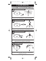
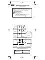
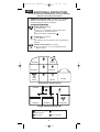
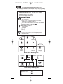
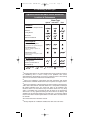
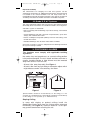
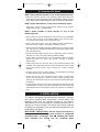
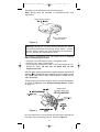
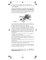
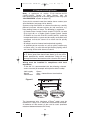
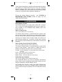
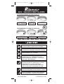
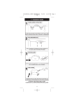
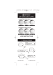
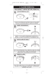
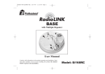
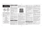
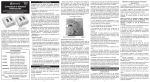
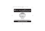
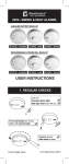
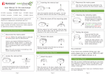
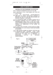
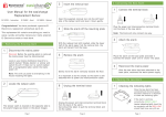
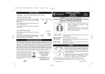
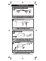
B16008-R0-160RC SERIES-U&C
17/1/07
11:13 AM
1.1 Installation Guide
2
Page 1
B16008-R0-160RC SERIES-U&C
17/1/07
11:13 AM
Page 2
2. ALARM REMOVAL
LOCATE REMOVAL SLOT
TO REMOVE PU
SH
S CREWDRIVER
INTO
SLO
& PUSH COVER
T
AWAY
LOCATE THE ARROW ON THE FRONT FACE OF THE ALARM.
THE SLOT IS LOCATED DIRECTLY ABOVE THE ARROW.
INSERT SCREWDRIVER
INSERT A FLAT-BLADED SCREWDRIVER HORIZONTALLY
APPROX. 1cm INTO THE CENTRE OF THE REMOVAL SLOT
SLIDE ALARM OFF BASE
WITH THE SCREWDRIVER STILL INSERTED, PUSH THE LOWER
HALF OF THE ALARM AWAY FROM THE SCREWDRIVER, IN THE
DIRECTION OF THE ARROW ON THE COVER
REMOVE ALARM
HOLD THE LOWER HALF OF THE ALARM AND REMOVE FROM
THE BASE PLATE BY MOVING IT VERTICALLY DOWNWARDS,
TOWARDS THE FLOOR.
3
B16008-R0-160RC SERIES-U&C
17/1/07
11:13 AM
Page 3
2. HOW MANY ALARMS TO INSTALL
- CATEGORIES & GRADES The advice here follows the guidance in British Standard
BS 5839-Part 6: 2004 in general (for further information see
the BS standard itself).
The main reason for fitting Smoke & Heat Alarms in dwellings
is to ensure that when there is a fire, sufficient early warning
is given so that everybody can escape safely.
This means that the fire alarms should ideally be located near
all potential sources of fires and that the alarm should be
heard throughout the house – particularly in the bedrooms.
It is also important that nuisance/false alarms are minimised
to ensure the units are not disabled or ignored.
The BS standard gives guidance on:
- how many alarms to install
- what type of alarm to use
- where to position alarms
The above points will depend on the type of dwelling to be
protected and the level of fire risk.
Fire Risk Assessment
The ‘Grade’ and ‘Category’ of system that should be installed
depends on the fire risk. The risk assessment is based on a
combination of probabilities:
- fire occurring
- injury or death to occupant
- system operating correctly with a fire
- early detection and warning to occupants in the event of a fire.
The greater the risks, the more comprehensive and reliable
systems are needed.
2.1 Categories of System
There are three Categories of LD systems for Life protection
in Dwellings that can be installed, depending on the fire risk
and regulations.
Please see following pages for detailed information.
4
B16008-R0-160RC SERIES-U&C
LD3
17/1/07
11:13 AM
Page 4
MINIMUM PROTECTION
for existing dwellings
Minimum Protection LD3: Smoke Alarms in all
hallways, stairways and circulation areas that form
part of the escape routes from the dwelling.
Smoke Alarms located:
on each storey
every 7.5 m of hallways and escape routes
within 3m of all bedroom doors
(apart from toilets & bathrooms )
Shower
Bedroom
Bedroom
Bathroom
Living
Room
Kitchen
Garage
Multi Storey Dwelling LD3
Bedroom
Bedroom
Bathroom
Bedroom
Kitchen / Dining Room
Living Room
Single Storey Dwelling LD3
Ionisation or Optical
Smoke Alarm
Optical Smoke Alarm
do not fit alarm
5
B16008-R0-160RC SERIES-U&C
17/1/07
11:13 AM
Page 5
LD2 ADDITIONAL PROTECTION
for new or materially altered dwellings or existing dwellings
with poor structural fire precautions
Additional Protection LD2: As LD3, but in addition
Smoke or Heat Alarms in all rooms or areas that
present a high fire risk to occupants.
Smoke Alarms located:
on each storey
every 7.5 m of hallways and escape routes
within 3m of all bedroom doors
(apart from toilets & bathrooms )
Heat Alarms located in:
each Kitchen
(Heat Alarms must be within 5.3m of potential fire
sources)
Smoke or Heat Alarms located in:
each Living room (i.e. most frequently used
daytime room)
Shower
Bedroom
Bedroom
Bathroom
Living
Room
Kitchen
Garage
Multi Storey Dwelling LD2
Bedroom
Bedroom
Bathroom
Bedroom
Kitchen / Dining Room
Living Room
Single Storey Dwelling LD2
Ionisation or Optical
Smoke Alarm
Optical Smoke Alarm
Heat Alarm
do not fit alarm
6
B16008-R0-160RC SERIES-U&C
LD1
17/1/07
11:13 AM
Page 6
OPTIMUM PROTECTION
for dwellings where occupants may be at high risk (e.g. elderly)
Optimum Protection LD1: As LD2, but in addition
Smoke or Heat Alarms should be located in all rooms
and other areas of the dwelling.
(apart from toilets or bathroom)
Smoke Alarms located:
on each storey
every 7.5 m of hallways and escape routes
within 3m of all bedroom doors
in all other rooms & areas other than listed below
(apart from toilets & bathrooms )
Heat Alarms located in:
each Kitchen
garages
(Heat Alarms must be within 5.3m of potential fire
sources)
Smoke or Heat Alarms located in:
each Living room (i.e. most frequently used
daytime room)
Shower
Bedroom
Bedroom
Bathroom
Living
Room
Kitchen
Garage
Multi Storey Dwelling LD1
Bedroom
Bedroom
Bathroom
Bedroom
Kitchen / Dining Room
Living Room
Single Storey Dwelling LD1
Ionisation or Optical
Smoke Alarm
Optical Smoke Alarm
Heat Alarm
do not fit alarm
7
B16008-R0-160RC SERIES-U&C
17/1/07
11:13 AM
Page 7
2.2 Selecting Alarm Type
Optical/Ionisation/Heat Alarm Selection
Locations & Performance
Optical
1
Alarm Type
Ionisation
2
Heat
Locations
Hall, Corridors, Escape Routes
Kitchens
3
Living Rooms
Bedrooms
Shower / Bathroom
Fire Response
Slow Smouldering Fires
(polyurethane foam, ignited bedding etc.)
Fast Flaming Fires
(chip pans, flaming wood/plastic, oil,
solvents etc.)
4
Temperature >580C
(only in areas with cooking fumes, steam,
very dirty/dusty)
Nuisance Alarm Immunity
5
Cooking Fumes
Steam, Condensation &
Dust Build-up
- Best
- Good
- Acceptable
- Not Suitable
1 Optical Smoke Alarms are recommended due to their excellent response
to smouldering fires. If there is likely to be problems with steam,
contamination or dust build-up, or if there is significant risk of a fast burning
clean fire an Ionisation Smoke Alarm should be fitted.
2 Some Fire Authorities recommend that both Ionisation and Optical
Smoke Alarms should be fitted for the fastest response to all types of fires.
3 Some Fire authorities (concerned with the slow response of Heat Alarms)
advise that Smoke Alarms should be fitted. This is acceptable according to
BS 5839-6 provided there are clearly not going to be problems with
nuisance alarms. Fit Heat Alarms only if nuisance alarms are very likely
and it is acceptable that a warning will only be given by the Heat Alarm
when there is a very significant flaming fire in the room. If the door(s) and
windows are not closed to contain the fire and heat, it is extremely unlikely
that the Heat Alarm would respond before a Smoke Alarm sited outside in
the corridor.
4 In enclosed kitchens with doors closed.
5 Greatly depends on ventilation and distance from source of fumes.
8
B16008-R0-160RC SERIES-U&C
17/1/07
11:13 AM
Page 8
Improved Audibility
The effectiveness of Category LD2 and LD3 systems can be
significantly enhanced if an additional Smoke Alarm (interconnected)
is installed in the master bedroom. This will help ensure that a
responsible person will quickly be alerted to a fire and can arrange for
an orderly evacuation of children and other vulnerable occupants.
2.3 Grade D, E & F Systems
The mains powered Smoke and Heat Alarms with battery back-up
covered by these instructions are suitable for Grade D, E & F Systems.
A Grade D system is needed for:
- new or materially altered dwellings, up to three-storeys, with no floor
over 200m2
- existing dwellings with poor structural fire precautions, up to three
storeys, with no floor over 200m2
- Houses in Multiple Occupation (HMOs) of one or two-storeys, with
no floor over 200m2
- Individual dwellings units of two or more rooms in HMOs
Check that a Grade D system is adequate for the dwelling into which
the system is being installed.
3. POSITIONING ALARMS
The locations must comply with applicable building
regulations.
Hot smoke rises and spreads out, so a central ceiling position
is the preferred location. The air is “dead” and does not move in
corners, therefore Smoke & Heat Alarms must be mounted
away from corners. Place the unit:
- At least 0.3m away from walls. See Figure 1.
- At least 0.3m from any light fitting or decorative object which
might obstruct smoke / heat entering the Alarm.
0.3m
0.9m
Figure 1
Figure 2
(Smoke Alarms should be located directly on the ceiling or, if not
possible, up to 575mm below it. Heat Alarms should be located directly
on the ceiling or, if not possible, up to 125mm below it).
Sloping Ceiling
In areas with sloping or peaked ceilings install the
Smoke/Heat Alarm 90cm from the highest point measured
horizontally (see Figure 2), because “dead air” at the apex
may prevent smoke from reaching the unit.
9
B16008-R0-160RC SERIES-U&C
17/1/07
11:13 AM
Page 9
3.1 Locations To Avoid
DON’T place Smoke Alarms in any of the following areas:
• Bathrooms, kitchens, shower rooms, garages or other rooms where the
smoke alarm may be triggered by steam, condensation, normal smoke or
fumes. Keep at least 6 metres away from sources of normal smoke/fumes.
DON’T place Heat Alarms in any of the following areas:
• Bathrooms, shower rooms or other rooms where the unit may be
triggered by steam or condensation.
DON’T place Smoke or Heat Alarms in any of the
following areas:
• Places where the normal temperature can exceed 40°C or be below
4°C (e.g. attics, furnace rooms, directly above ovens or kettles etc.)
as the heat/steam could cause nuisance alarms.
• Near a decorative object, door, light fitting, window moulding etc.,
that may prevent smoke or heat from entering the Alarm.
• Surfaces that are normally warmer or colder than the rest of the room
(e.g. attic hatches). Temperature differences might stop smoke or heat
from reaching the unit.
• Next to or directly above heaters or air conditioning vents, windows,
wall vents etc. that can change the direction of airflow.
• In very high or awkward areas (e.g. over stairwells) where it may be
difficult to reach the alarm (for testing, hushing or battery
replacement).
• Locate away from very dusty or dirty areas as dust build-up in the
chamber can impair performance. It can also block the insect screen
mesh and prevent smoke from entering the smoke detector
chamber.
• Locate the unit at least 1m from dimmer controlled lights and wiring
as some dimmers can cause interference.
• Locate unit at least 1.5m and route wiring at least 1m away from
fluorescent light fittings as electrical “noise” and/or flickering may
affect the unit. Do not wire into the same circuit as fluorescent lights
or dimmers.
• Do not locate in insect infested areas. Small insects getting into the
smoke detector chamber can cause intermittent alarms. Insects and
contamination on the Heat Alarm sensor can increase its response
time.
4. INSTALLATION
The Alarm is designed to be permanently mounted , using it’s
own built-in terminal block to connect it to the mains. The
mounting plate can be screwed directly to the ceiling.
Alternatively it can be screwed to a standard junction box. It
requires a current of 40mA. The Alarm must not be exposed
to dripping or splashing. There are important markings on the
underside of the alarm.
IMPORTANT PRECAUTION: Do not install the Alarms in
new or renovated buildings until all work is completed
(including floor coverings) and the building has been
fully cleaned. The wiring can be installed when
10
B16008-R0-160RC SERIES-U&C
17/1/07
11:13 AM
Page 10
appropriate. (Excessive dust and debris from building
work can contaminate the smoke chamber or heat sensor
and cause problems, it will also invalidate the guarantee).
If it must be installed, first cover it completely, particularly
around the edges, with a dust cover (eg. with the
elasticated cover supplied or a plastic bag), until all
cleaning is finished.
The Alarm must not be connected when the house wiring
insulation is being checked with high voltages.
i.e. Do not use a high voltage insulation tester on the alarm.
WARNING: Mains operated Alarms should be installed and
interconnected by a qualified electrician in accordance with
the Regulations for Electrical Installations published by the
Institution of Electrical Engineers (BS7671). Failure to install
this Alarm correctly may expose the user to shock or fire hazards.
WARNING: The Alarm must be continuously powered 24
hours a day so it is important that it is not on a circuit that can
be turned off by a switch.
Note: BS 5839-6 2004 gives the folowing recommendations regarding the
mains supply to be used in a Grade D system (The Ei141/146
/161RC/166RC Smoke Alarms and Ei144/164RC Heat Alarms can be used
in a Grade D system). The power supply for the Alarms should be derived
from the public electricity supply to the dwelling. The mains supply to the
Alarms should take the form of either:
(a) an independent circuit at the dwelling’s main distribution board, in which
case no other electrical equipment should be connected to this circuit
(other than a dedicated monitoring device installed to indicate failure of the
mains supply to the Alarms); or
(b) a separately electrically protected, regularly used local lighting circuit.
Alarms should be connected on a single final circuit, unless the means of
interconnection is by radio signals (e.g. RadioLINK).
(See BS 5839-6: 2004 for further information)
Note: The Ei Electronics RadioLINK Base Ei168RC (for use with
Ei161RC/164RC/166RC models only) can be used to eliminate
interconnect wiring, make system extensions and provide simple and cost
effective compliance with BS 5839-6: 2004.
4.1 Mounting & Wiring Alarms
1. Select a location complying with the advice in previous
sections (see pages 4-10).
2. Disconnect the AC mains supply from the circuit that is
going to be used.
3. Lift off the wiring cover as shown in Figure 3.
The house wiring must be connected to the terminal block on
the mounting plate as follows:
L: Live - connect to the house wires coloured brown or
marked L.
N: Neutral - connect to the house wires coloured blue or
marked N.
11
B16008-R0-160RC SERIES-U&C
17/1/07
11:13 AM
Page 11
See page 14 for information on interconnection.
Note: Wiring must be installed in compliance with local
regulations.
FOAM CEILING GASKET
INSERT SCREWDRIVER
TO LIFT AND REMOVE
WIRING COVER
Figure 3
Warning: Mixing the Live and Neutral connections when
interconnecting alarms will damage all the alarms - ensure
that the same colours are used throughout the premises
for Live, Neutral and Interconnect wires.
We strongly recommend that you check for the following
before connecting the alarm:
• check for Live and Neutral using a two probe tester.
• check for Live using a neon tester.
• check that the Interconnect wire is NOT connected to Live,
Neutral or Earth. Do not use an Earth wire for the
Interconnect line.
N.B. The alarm does not need to be earthed. However the terminal
marked
is provided for the convenience of the installer so that
any copper Earth wire or cable coloured green & yellow, can be
safely terminated.
To interconnect the Alarms connect all the IC terminals together
as shown in Figure 4 (see “Interconnecting Alarms” section
on page 14).
REMOVEABLE
TRUNKING DOOR FOR
Figure 4
4. If the mains wires are recessed, bring the wires through the
rear hole in the mounting plate as shown in Figure 4.
12
B16008-R0-160RC SERIES-U&C
17/1/07
11:13 AM
Page 12
If the mains wires are being brought along the surface:
(a) position the mounting plate so the cable trunking is as
shown in Figure 4.
(b) the mounting plate has a removable section, take it out to
interface directly with 25 mm conduit as shown in Figure 5. If
interfacing to 16 mm conduit carefully cut around the marked
section, leaving the top intact and replace the section. (If you
are not using surface wiring, the removable section must be
left in place for electrical safety reasons).
Figure 5
There are two other positions which are also suitable for the
surface wiring to enter (and exit) the alarm, one next to the
removable section and another directly opposite.
5. Carefully align the mounting plate and screw into place.
Connect the wires to the terminal block. With recessed wiring,
ensure the rear gasket seals around the edge of the hole in
the ceiling or wall. This is to prevent air draughts affecting the
smoke/heat entering the alarm. If the hole is too large or the
alarm does not seal it, it should be sealed with silicone rubber
or equivalent.
6. Replace the wiring cover. Check the alarm battery is
connected (Ei141/144/146 only).
7. Carefully line up the unit on the base and slide on.
8. Press and hold the test/hush button for 10 seconds. The
horn will sound. Check that any interconnected alarms also
sound within this period.
9. Connect the mains power to the alarm circuit. Check the
green light is on.
10. Attach the ‘Smoke Alarm’ identification label provided to
the distribution board to identify the alarm circuit.
11. Attach the ‘Mains Smoke / Heat Alarms’ label provided on
or near the distribution board and write in date installed and
the number of alarms on the circuit.
Ensure the alarm operates correctly - see “TESTING &
MAINTAINING YOUR ALARM” section on page 4 of the
USER INSTRUCTIONS.
13
B16008-R0-160RC SERIES-U&C
17/1/07
11:13 AM
Page 13
4.2 Interconnecting Alarms
Note: A maximum of twelve Ei141/144/146/161RC
/164RC/166RC Smoke or Heat Alarms may be
interconnected along with an Ei128R pattress with relay (see
“ACCESSORIES” section on page 15).
If you wish to connect more than twelve alarms contact your
local distributor (see page 16 for details).
Systems using more than 3 or 4 alarms must be very carefully
planned to ensure nuisance alarms are not excessive. e.g.
from cooking fumes or steam. The following is suggested:
• A Smoke Alarm Locator Switch (model Ei159 for use with
Ei141/144/146) or a Smoke Alarm Control Switch (model
Ei1529RC for use with Ei161RC/164RC/166RC) should be
incorporated into the system and be readily accessible to all
occupants so that the source of an alarm can be quickly
identified.
• All alarms must be cleaned and maintained regularly.
• A qualified person must be on call to quickly remove any
nuisance units (i.e. units with red light flashing rapidly) which
are causing all the other alarms to sound.
WARNING: Do not connect these Alarms to any other type
of Ei Alarm (apart from those listed above) or to any other
model produced by another manufacturer. Doing so may
damage the Alarms and could result in a shock or fire hazard.
Wiring must be installed in compliance with local
regulations.
In the UK it is recommended that the following coloured
cores are used (for example with triple flat 6243Y cable).
230V supply
Neutral
Interconnect
Brown
Grey - sleeved blue at terminations
Black
Figure 6
The interconnect wire (minimum 0.75mm2 cable) must be
treated as if it was Live. It should be insulated and sheathed.
A maximum of 250 metres of wire can be used (maximum
resistance between detectors 50 Ohms).
14
B16008-R0-160RC SERIES-U&C
17/1/07
11:13 AM
Page 14
These Smoke/Heat Alarms should be interconnected only within
the confines of a single family living unit. If they are connected
between different units there may be excessive nuisance
alarms. Everybody may not be aware that they are being tested
or that it is a nuisance alarm caused by cooking etc.
Ensure the alarms operate correctly - see “TESTING &
MAINTAINING YOUR ALARM” section on page 4 of the
USER INSTRUCTIONS.
5. ACCESSORIES
Relay Module Ei128R:
The Ei128R module has a relay rated at 250V AC / 5 Amps.
This is useful for remote signalling and turning on lights etc.
Also available is the Ei128RBU Relay Module which has
battery back-up.
Alarm Locator Ei159:
(for use with models Ei141/144/146 only)
The Smoke Alarm locator is recommended for systems with
three or more Smoke / Heat Alarms as it helps quickly identify
the unit in alarm and reduces the impact of nuisance alarms.
Pressing the Smoke Alarm Locator button will silence all
interconnected alarms for 10 minutes, except those sensing
fire. It is easily installed between the Interconnect and Neutral
terminals.
Alarm System Control Switch Ei1529RC:
(for use with models Ei161RC/164RC/166RC only)
The System Control Switch is recommended for systems with
three or more Smoke / Heat Alarms. It allows the user to
perform the following functions from a remote location:
LOCATE - If alarms sound press Locate to allow source of alarm to be
identified.
HUSH - Press Hush to silence nuisance alarms.
TEST - Operate weekly to Test the alarms.
MAINS CHECK - Test will not work with mains absent.
RadioLINK Base Ei168RC:
(For use with models Ei161RC/164RC/166RC only)
The RadioLINK Bases are used to eliminate interconnect
wiring, make system extensions and provide simple and cost
effective compliance with BS 5839-6: 2004.
An Ei168RC with Ei161RC, 164RC and 166RC Smoke/Heat
Alarms allows the units to be remotely tested, silenced and
the fire located using the optional Ei411H RadioLINK control
switch.
15
B16008-R0-160RC SERIES-U&C
17/1/07
11:13 AM
Page 15
INDEX
1
1. QUICK GUIDE
1.1 INSTALLATION GUIDE
2
1.2 ALARM REMOVAL
3
4
2. HOW MANY ALARMS TO INSTALL
2.1 CATEGORIES OF SYSTEM
4
2.2 SELECTING ALARM TYPE
8
2.3 GRADE D, E & F SYSTEMS
9
9
3. POSITIONING ALARMS
3.1 LOCATIONS TO AVOID
10
10
4. INSTALLATION
4.1 MOUNTING & WIRING ALARMS
11
4.2 INTERCONNECTING ALARMS
14
15
5. ACCESSORIES
Aico Ltd. Mile End Business Park, Maesbury Rd, Oswestry,
Shropshire SY10 8NN, U.K.
Tel: 0870 758 4000
www.aico.co.uk
Ei Electronics. Shannon, Co Clare, Ireland. Tel: 061 471277
www.eielectronics.com
16
B16008-R0-160RC SERIES-U&C
17/1/07
11:13 AM
Page 16
230V~ SMOKE & HEAT ALARMS
ALKALINE PRIMARY BATTERY BACK-UP
Ei141 - Ionisation
Ei146 - Optical
Ei144 - Heat
RECHARGEABLE LITHIUM CELL BACK-UP
Ei161RC - Ionisation
Ei164RC - Heat
Ei166RC - Optical
INSTALLER INSTRUCTIONS
IDEALLY INSTALL IN THE CENTRE OF CEILING
AT LEAST 300mm FROM LIGHT FITTINGS
LOCATE IONISATION ALARMS AWAY FROM
KITCHENS TO PREVENT NUISANCE ALARMS
INTERCONNECT ALL ALARMS
ENSURE LIVE MAINS IS CORRECTLY
CONNECTED TO L TERMINALS ON ALL
INTERCONNECTED ALARMS - OTHERWISE
UNITS WILL BE DAMAGED
DO NOT FIT ACTUAL ALARM UNTIL ALL
BUILDING WORK IS COMPLETED TO AVOID
CONTAMINATION. AFTER CHECKING
OPERATION, COVER SMOKE ALARM WITH
DUST COVER UNTIL REQUIRED FOR USE
DISCONNECT THE ALARM BEFORE APPLYING
HIGH VOLTAGE INSULATION TESTS TO WIRING
DO NOT ATTEMPT TO OPEN THE ALARM AS
IT IS PERMANENTLY SEALED FOR SAFETY
P/N B16008 Rev0
© Ei Electronics 2006