1
®
Security
Systems
UNI•COM
Universal Digital Alarm Communicator/Transmitter
for the Unimode Series Fire Alarm Systems
Product Information, Installation,
Programming and Operation Manual
Document # 50075
3/13/95
Rev:
P/N 50075:B
B
ECN 95-107
Don't Forget Installation Precautions
2
Document # 50075 Rev B 3/13/95
NFPA Standards, UL Documents
1.0
1.1
Table of Contents
1.2
1.3
1.4
1.5
1.6
1.7
1.8
1.9
2.0
2.1
2.3
2.4
3.0
3.1
3.2
5
Product Description
Product Features
Figure 1-1: UNI•COM Assembly
Controls and Indicators
Figure 1-2: Controls and Indicators
Compatible Panels
Digital Communicator
Circuits
Optional Device
Specifications
Telephone Requirements and Warnings
1.8.1 Telephone Circuitry
1.8.2 Digital Communicator
1.8.3 Telephone Company Rights and Warnings
1.8.4 For Canadian Applications
Modes and Special Functions
1.9.1 Normal Mode
1.9.2 Serviceman Code
1.9.3 Program Mode
1.9.4 Walktest Mode
1.9.5 Troubleshoot Mode
1.9.6 Type Mode
1.9.7 Clear Function
1.9.8 Manual Test Function
1.9.9 Lamp Test Mode
1.9.10 User Code
6
6
7
8
8
8
8
9
9
10
10
10
10
10
11
12
12
12
12
12
12
12
12
12
12
12
Installation & Wiring
General
Output Circuits
Figure 2-1: Wiring Phone Jacks
Figure 2-2: Relay Driver Connections
Figure 2-3: Monitoring for UNI•COM Trouble
UL Power-limited Wiring Requirements
Figure 2-4: Typical Wiring for UL Power-limiting
13
13
13
13
14
15
16
16
Programming Instructions
Entering Program Mode
Switch Functions
Figure 3-1: UNI•COM Keypad
17
17
18
18
Document # 50075 Rev B 3/13/95
3
Table of Contents
4
3.3
Programming Options
Table 3-1: Start and End Monitoring Address
Table 3-2: Event Codes, Primary Number
Table 3-3: Event Codes, Primary Number
18
20
23
24
4.0
4.1
4.5
Operating Instructions
Normal Mode
4.1.1 Keys
4.1.2 Displays
Figure 4-1: UNI•COM Phone Connectors & LEDs
4.1.3 Normal Mode Operation
4.1.4 Key Report Descriptions
Walktest Mode
Type Mode
Troubleshoot Mode
Figure 4-2: Handset/Speaker Connection
Lamp Test Mode
25
25
25
26
27
27
29
31
32
33
33
34
5.0
Compatible Receivers
35
6.0
Programming Reference Sheets
36
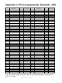
Appendix A: Point Assignments - Unimode 200
42
Appendix B: Zone Assignments - Unimode 4-16
43
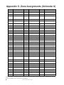
Appendix C: Zone Assignments - Unimode II
44
Appendix D: Unimode 200
45
Appendix E: Unimode 4-16
47
Appendix F: Unimode II
49
4.2
4.3
4.4
Document # 50075 Rev B 3/13/95
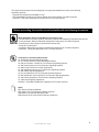
This digital communicator has been designed to comply with standards set forth by the following
regulatory agencies:
• Underwriters Laboratories Standard UL 864
• NFPA Standards 72-1993 Local, Remote Station and Central Station Fire Alarm Systems
• CAN/ULC - S527-M87 Standard for Control Units for Fire Alarm Systems
Before proceeding, the installer should be familiar with the following documents.
NFPA Standards, NFPA 72-1993 National Fire Alarm Code:
• Central Station Fire Alarm Systems (Automatic, Manual and Waterflow) Protected Premises Unit.
• Local (Automatic, Manual, Waterflow and Sprinkler Supervisory) Fire Alarm Systems.
• Proprietary Fire Alarm Systems (Protected Premises Unit).
• Automatic Fire Detectors
• Installation, Maintenance, and Use of Notification Appliances for Fire Alarm Systems
• Inspection, Testing and Maintenance for Fire Alarm Systems
Underwriters Laboratories Documents:
UL 38 Manually Actuated Signaling Boxes
UL 217 Smoke Detectors, Single and Multiple Station
UL 228 Door Closers—Holders for Fire Protective Signaling Systems
UL 268 Smoke Detectors for Fire Protective Signaling Systems
UL 268A Smoke Detectors for Duct Applications
UL 346 Waterflow Indicators for Fire Protective Signaling Systems
UL 464 Audible Signaling Appliances
UL 521 Heat Detectors for Fire Protective Signaling Systems
UL 864 Standard for Control Units for Fire Protective Signaling Systems
UL 1481 Power Supplies for Fire Protective Signaling Systems
UL 1638 Visual Signaling Appliances
CAN/ULC - S524-M91 Standard for Installation of Fire Alarm Systems
Other:
NEC Article 300 Wiring Methods
NEC Article 760 Fire Protective Signaling Systems
Applicable Local and State Building Codes
Requirements of the Local Authority Having Jurisdiction
Document # 50075 Rev B 3/13/95
5
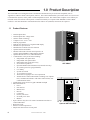
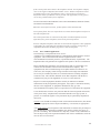
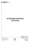
1.0 Product Description
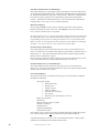
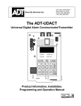
The UNI•COM Universal Digital Alarm Communicator/Transmitter may be used with compatible (refer to
Appendices) ADT fire alarm control panels (FACPs). The UNI•COM transmits system status to the UCS (Universal
Communication System) via the public switched telephone network. The UNI•COM is compact in size and may be
mounted inside selected host control panels or mounted externally in a separate ADT-ABS8RF or ADT-UBS1F
enclosure. EIA-485 annunciator communications bus and 24 volt (nominal) connections are required.
1.1
Product Features
• Dual telephone lines
• Dual telephone line voltage detect
• Surface mount technology
• Compact in size: 6.75" x 4.25"
• Built-in programmer
• Built-in four character red 7-segment LED display
• Manual test report function
• Manual master transmission clear function
• Optional Zone/Point disable
• Mounts either inside selected control panels or in
separate ADT-ABS8RF or ADT-UBS1F enclosure
• Optional Dead Front Cover (ADT-DPUBS1F)
• Communicates vital system status including:
ü Independent zone/point alarm
ü Independent zone/point trouble
ü Independent zone/point supervisory
ü Serviceman on premises
ü Optional Walktest data transmission (Unimode 200 only)
ü AC (mains) power loss (programmable)
ü Low battery
ü System off normal
ü 12 or 24 hour test signal
ü Abnormal test signal per new UL requirements
ü Annunciation of UNI•COM troubles including: loss of phone
lines, communication failure with either central station, total
communication failure
• Troubleshoot mode converts keypad to DTMF touchpad
• Individual LEDs for:
ü Power
ü EIA-485 loss
ü Manual Test
ü Kissoff
ü Comm Fail
ü Primary Line Seize
ü Secondary Line Seize
ü Modem
• Open collector relay driver for Total Communication Failure or
UNI•COM trouble.
• Real Time Clock
• Extensive transient protection
• Simple EIA-485 interface to host panel
6
Document # 50075 Rev B 3/13/95
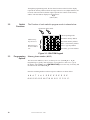
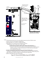
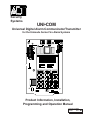
ADT-UBS1F
Optional ADT-DPUBS1F
Primary
Phone Line
Secondary
Phone Line
Modular Cables
P/N MCBL-7
(Order Separately)
Make No Connection
Comm Fail Output
(power-limited)
24 VDC Power in
(use power-limited
source)
24 VDC
(power-limited)
EIA-485 Connector
(use power-limited
source)
Connector
on back of
board
Figure 1-1: UNI•COM Assembly
Document # 50075 Rev B 3/13/95
7
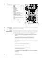
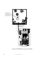
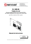
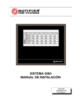
1.2
Controls and
Indicators
Front Panel Switches
CLEAR
TEST
MODE
Up Arrow
Down Arrow
1st EVENT
ENTER/STORE
Digits 0-9
A
B
C
D
E
F
Displays
• EIA-485 - yellow LED
• COMM. FAIL - yellow LED
• KISS OFF - green LED
• POWER - green LED
• Four, Seven Segment Displays red
• Primary Phone Line Active - red
LED
• Secondary Phone Line Active - red
LED
• TEST - green LED
• MODEM - green LED
Figure 1-2: Controls and Indicators
1.3
Compatible
Panels
The UNI•COM has been designed to be compatible with a variety of ADT fire alarm
control panels (refer to Appendices).
1.4
Digital
Communicator
Two modular phone jacks allow easy connection to telephone lines. Modular jacks
are labeled PH1 and PH2 for the Primary and Secondary phone lines. Telephone line
'Primary and Secondary Active' red LEDs are provided as well as a green 'Kissoff'
LED. The integral digital communicator provides the following functions:
• Line Seizure - takes control of the phone lines disconnecting any premises
phones.
• Off/On Hook - perform on and off-hook status to the phone lines.
• Listen for dial tone - 440 hertz tone typical in most networks.
• Dialing the central station(s) number - default is Touch-Tone®, programmable
to rotary.
• Discern proper synchronization with UCS receiver.
• Transmit data to UCS receiver.
• Verify data has been accepted by the UCS receiver.
• Hang up and release phone lines.
• Communicate in the ADT FSK II format (refer to Section 5.0 for compatible
receivers):
8
Document # 50075 Rev B 3/13/95
1.5
Circuits
The UNI•COM circuit board contains a CPU, other primary components and wiring
interface connectors.
1.5.1 Power Requirements
Operating voltage for the UNI•COM must be power-limited, filtered, nonresettable
21.2 to 28.2 volts. The 24 VDC nominal operating power must be supplied by the
Control Panel and is connected to TB1 of the UNI•COM.
Note: If the UNI•COM is installed in a Unimode 200 Control Panel, power is
provided directly through UNI•COM connector J10 which plugs into the Unimode
200 main circuit board.
1.5.2 Communications
Communications between the UNI•COM and the host control panel is accomplished
over a two wire EIA-485 serial interface which is power-limited and supervised by
the control panel and the UNI•COM. The wiring connections are made to the RS+,
RS- and Shield terminals of TB1 on the UNI•COM.
The EIA-485 circuit cannot be T-Tapped and must be wired in a continuous fashion
from the control panel to the UNI•COM and, if installed, an annunciator. The wire
must be 12AWG to 18AWG twisted shielded pair cable with a Characteristic
Impedance of 120 Ohms, +/-20%. Limit the total wire resistance to 100 Ohms on the
EIA-485 circuit. Do not run cable adjacent to, or in the same conduit as 120 volts
AC service, noisy electrical circuits that are powering mechanical bells or horns,
audio circuits above 25 voltsRMS, motor control circuits, or SCR power circuits.
Note: If the UNI•COM is installed in a Unimode 200 Control Panel, the EIA-485
data line is connected directly through UNI•COM connector J10 which plugs into
the Unimode 200 main circuit board.
1.5.3 Primary and Secondary Phone Lines - Modular jacks are used to interface
the primary and secondary phone lines to the public telephone network.
1.5.4 Communicator Fail Relay Driver - Relay driver output for central station
communication failure is available.
1.5.5 Earth Ground - Connect a separate earth ground wire to TB3 terminal 1 for
transient protection. When mounted in the Unimode 200, the UNI•COM receives an
earth ground connection via a metal standoff located on the upper right corner
mounting position.
1.6 Optional Device
Future use.
Document # 50075 Rev B 3/13/95
9
1.7
Specifications
DC Power - TB1, Terminals 1 & 2
24 VDC (nominal) filtered, non-resettable and power-limited. Voltage range is 21.2
to 28.2 volts. DC Power TB1 Terminals 1 (+), 2 (-) 40 mA in standby, 75 mA max.
while communicating (for installation in the Unimode 200 enclosure use connector
J10) and 100 mA with the open collector output engaged and communicating.
Data Communications - TB1, Terminals 3 - 7
EIA-485 serial interface, TB1 Terminal 3 = RS+, 4 = RS-, 5= Shield, 6 = Future use,
7 = Future use. Power-limited source must be used. (For installation in the Unimode
200 use connector J10).
Auxiliary Output - TB3, Terminals 2 & 3
TB3-2 = Communicator Failure. Power-limited circuit. An Open Collector type
output, normally high, active low which sinks up to 40 mA. TB3-3 = 21.2 to 28.2
volts, power-limited. Use UL listed relay P/N: MR-101/C or MR-201/C with this
output.
Earth Ground - TB3, Terminal 1
TB3-1 = Earth Ground connection. Connect this terminal to building earth ground
using solid 12 AWG wire to provide lightning protection. This connection is not
required when the UNI•COM is mounted in a Unimode 200 since the metal standoff
used in mounting provides an earth ground connection.
1.8
Telephone
Requirements
and Warnings
1.8.1
Telephone Circuitry - PH1 & PH2
Ringer Equivalence Number (REN) = 0.6B
AC Impedance 10.0 Mega Ohm
Complies with FCC Part 68
Mates with RJ31X Male Connector
Supervision Threshold: less than 4.0 volts for 2 minutes
The REN is used to determine the quantity of devices which may be connected to the
telephone line. Excessive REN's on the telephone line may result in the devices not
ringing in response to an incoming call. In most, but not all areas, the sum of the
REN's should not exceed five (5.0). To be certain of the number of devices that may
be connected to the line, as determined by the total REN's, contact the telephone
company to determine the maximum REN for the calling area.
1.8.2
Digital Communicator:
Before connecting the UNI•COM to the public switched telephone network, the
installation of two RJ31X jacks is necessary. The following information is provided
if required by the local telephone company :
Manufacturer :
Fire·Lite Alarms Inc.
12 Clintonville Rd.
Northford, CT 06472
Product Model Number: UNI•COM
FCC Registration Number: 1W6USA-20723-AL-E
Ringer Equivalence 0.6B
1.8.3
Telephone Company Rights and Warnings:
The telephone company under certain circumstances may temporarily discontinue
services and/or make changes in its facilities, services, equipment or procedures
which may affect the operation of this control panel. However, the telephone
company is required to give advance notice of such changes or interruptions.
10
Document # 50075 Rev B 3/13/95
If the control panel causes harm to the telephone network, the telephone company
reserves the right to temporarily discontinue service. Advance notification will be
provided except in cases when advance notice is not practical. In such cases,
notification will be provided as soon as possible. The opportunity will be given to
correct any problems and to file a complaint.
DO NOT CONNECT THIS PRODUCT TO COIN TELEPHONE, GROUND START,
OR PARTY LINE SERVICES.
When the control panel activates, premise phones will be disconnected.
Two separate phone lines are required. Do not connect both telephone interfaces to
the same telephone line.
The control panel must be connected to the public switched telephone network
upstream of any private telephone system at the protected premises.
An FCC compliant telephone cord must be used with this equipment. This equipment
is designed to be connected to the telephone network or premises wiring using a
compatible RJ31X male modular plug which is Part 68 compliant.
1.8.4
For Canadian Applications
The following is excerpted from CP-01 Issue 5:
"NOTICE: The Canadian Department of Communications label identifies certified
equipment. This certification means that the equipment meets certain
telecommunications network protective, operational and safety requirements. The
Department does not guarantee the equipment will operate to the user's satisfaction.
Before installing this equipment, users should ensure that it is permissible to be
connected to the facilities of the local telecommunications company. The
equipment must also be installed using an acceptable method of connection. In
some cases, the company's inside wiring associated with a single line individual
service may be extended by means of a certified connector assembly (telephone
extension cord). The customer should be aware that compliance with the above
conditions may not prevent degradation of service in some situations.
Repairs to certified equipment should be made by an authorized Canadian
maintenance facility designated by the supplier. Any repairs or alterations made by
the user to this equipment, or equipment malfunctions, may give the
telecommunications company cause to request the user to disconnect the equipment.
Users should ensure for their own protection that the electrical ground connections
of the power utility, telephone lines and internal metallic water pipe system, if
present, are connected together. This precaution may be particularly important in
rural areas.
Caution: Users should not attempt to make such connections themselves, but should
contact the appropriate electric inspection authority, or electrician, as appropriate."
"The Load Number (LN) assigned to each terminal device denotes the percentage of
the total load to be connected to a telephone loop which is used by the device, to
prevent overloading. The termination on a loop may consist of any combination of
devices subject only to the requirement that the total of the Load Numbers of all the
devices does not exceed 100."
Document # 50075 Rev B 3/13/95
11
Industry Canada (IC) Compliance - "This digital apparatus does not exceed the Class
A limits for radio noise emissions from digital apparatus set out in the Radio
Interference Regulations of the Canadian Department of Communications."
IC Registration Number: 2132 6030 A
Load Number: 3
1.9
Modes and
Special
Functions
1.9.1 Normal Mode:
Normal mode is the standard mode of operation in which the UNI•COM monitors
host FACP status as well as telephone line voltage. The UNI•COM reports system
status information to UL listed Central Station Receivers. Information transmitted
includes zone/point: fire alarm, fire alarm trouble and supervisory alarm. Specific
system trouble conditions and specific UNI•COM troubles are also transmitted.
1.9.2 Serviceman Code:
The serviceman code, once entered, allows access to program, walktest, troubleshoot
and type modes. The serviceman code also enables the clear function. Refer to
following sections.
1.9.3 Program Mode:
Program mode is used to program the UNI•COM. While the UNI•COM is in the
program mode, it cannot receive host FACP status information. See Section 3.0 for
complete programming instructions.
1.9.4 Walktest Mode:
While in the walktest mode, transmission of FACP system events may be optionally
transmitted to the UCS receiver (Central Station).
1.9.5 Troubleshoot Mode:
Troubleshoot mode may be used for testing the telephone line wiring. Connection
from the UNI•COM's modular jacks, through RJ31X jacks and into the telephone
network may be easily checked. In this mode, the keypad acts similar to a telephone
touchpad.
1.9.6 Type Mode:
Type mode is used to program into the UNI•COM the system zones/points which are
non-fire alarm, i.e. supervisory type. This mode is also used to disable the alarm
report for any zone/point in the system. The feature which disables the zone/point
alarm report must be used for zones/points programmed into the host FACP as
remote silence, reset, drill or acknowledge switches.
1.9.7 Clear Function:
When the clear function is activated, it causes the UNI•COM to immediately stop
transmissions, disconnect from the telephone network, clear out any messages that
were waiting for transmission and reset.
1.9.8 Manual Test Function:
The manual test function allows a test report message to be sent to both central
stations upon activation. A Serviceman Code is not required.
1.9.9 Lamp Test Mode:
The UNI•COM 4-character display segments plus all LEDs illuminate in this mode.
1.9.10 User Code:
The user code, once entered, allows for user level testing and maintenance functions.
The user may be allowed to transmit walktest data to the UCS for the Unimode 200
system.
12
Document # 50075 Rev B 3/13/95
2.0 Installation and Wiring
2.1
General
2.2
Output Circuits
For information on installing the UNI•COM in a specific ADT fire alarm control
panel, refer to the appropriate Appendix.
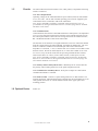
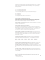
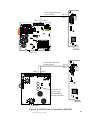
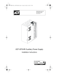
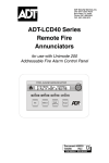
Telephone Circuits
Provision to connect to two independent telephone lines is available via two
telephone jacks labeled PH1 (Primary) and PH2 (Secondary). Telephone line control/
command is possible via double line seizure as well as usage of an RJ31X style
interconnection. (RJ31X jacks must be ordered separately).
Note: It is critical that the UNI•COM be located as the first device on the incoming
telephone circuit to properly function.
(Primary Lines)
Incoming Telco
Phone Lines
Tip
Ring
Ring
Green Wire
Red Wire
Tip
Green Wire
Ring
Red Wire
(Secondary Lines)
Incoming Telco
Phone Lines
Ring
To premise phones
To premise phones
Tip
Tip
Note: Shorting bars
inside RJ31X Jack
removed during male
plug insertion
Primary
Phone Line
PH-1
7 foot
Cable
(MCBL-7)
Order Separately
Secondary
Phone Line
PH-2
Male Plug
Connectors
Modular Female
Connectors
Make No
Connection
Figure 2-1: Wiring Phone Jacks
Document # 50075 Rev B 3/13/95
13
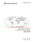
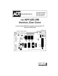
Relay Driver
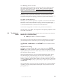
The UNI•COM's open collector output on TB3, terminal 2 is provided for Communicator Failure and UNI•COM trouble. It can be used to drive UL listed relay MR-101/
C or MR-201/C. The output is rated for 40 mA and is power-limited. The normal
condition for the output is Off (deenergized).
Communicator Failure occurs when the maximum number of attempts to reach both
central stations has taken place or when both phone lines are disconnected.
UNI•COM trouble conditions include loss of telephone line voltage to the primary or
secondary phone lines, communication failure to the primary or secondary central
stations or entry into Programming, Troubleshoot or Type Mode..
Wiring from the UNI•COM terminal TB3 to the relay must be in the same room no
more than 20 feet in length and enclosed in conduit. Wiring from the relay output
contacts must also remain in the same room as the UNI•COM.
When the UNI•COM is programmed as 'Receive Only' (typically this occurs when
annunciators are also used and are set for 'Receive/Transmit'), the relay output is
used to provide a UNI•COM trouble input to the host control panel. For Unimode
200 applications, use a monitor module to supervise the relay closure. Refer to
Figure 2-3. Program the adjective and noun fields for 'DACT Trouble'. For
Unimode II or Unimode 4-16 applications, wire the relay output to the annunciator
trouble input circuit or use the relay to trigger zone trouble.
When the UNI•COM is programmed as 'Receive/Transmit', EIA-485 supervision and
UNI•COM trouble status are automatically handled by the host control panel.
Relay Energized LED
TB3
Earth Gnd
Comm Fail
+24 VDC
DPDT Contacts
10 Amps
@ 115 VAC
All wiring to relay must
be in same room within
20 feet of UNI•COM and
in conduit.
MR-201/C *
Connections must be
in same room as
UNI•COM
Relay Energized LED
TB3
SPDT Contacts
10 Amps
@ 115 VAC
Earth Gnd
Comm Fail
+24 VDC
MR-101/C *
* Note: The MR-101/C and MR-201/C include an enclosure.
Figure 2-2: Relay Driver Connections
14
Document # 50075 Rev B 3/13/95
SLC Loop to Fire Alarm
Control Panel
M-300 Series Monitor Module
Wiring in
same room
as UNI•COM
TB3
All wiring to relay must
be in same room within
20 feet of UNI•COM and
in conduit.
3.9K EOL
Resistor
(supplied)
Earth Grnd
Comm Fail
+24 VDC
DACT
MR-101/C
(MR-201/C may also be used)
Note: 1) M-300 Series Monitor Module is used to supervise Normally Closed output of M-101/C. On
DACT trouble and Comm Fail, MR-101/C relay contact will open causing M-300 to transmit
trouble condition to FACP.
Figure 2-3: Monitoring for UNI•COM Trouble
Document # 50075 Rev B 3/13/95
15
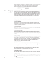
2.3
UL Powerlimited Wiring
Requirements
Power-limited and nonpower-limited circuit wiring must remain separated in the
cabinet. All power-limited circuit wiring must remain at least 0.25" away from any
nonpower-limited circuit wiring. Furthermore, all power-limited circuit wiring and
nonpower-limited circuit wiring must enter and exit the cabinet through different
knockouts and/or conduits. A typical wiring diagram for the UNI•COM is shown
below.
Use power-limited source
Power-limited circuits
Figure 2-4: Typical Wiring Diagram for UL Power-limited Requirements
16
Document # 50075 Rev B 3/13/95
3.0 Programming Instructions
Programming Mode
Programming of the UNI•COM is possible at any time including while the UNI•COM
is communicating with a central station.
The UNI•COM has a built-in programmer. All programming selections are stored in
nonvolatile Electrically-Erasable Programmable Read-Only Memory (EEPROM).
This ensures that the UNI•COM will retain all entries made in programming mode
even if power is removed.
The user must program the primary and secondary phone numbers, account numbers
and 24 hour test report times for each central station account and the current time.
The UNI•COM comes with factory chosen options/features already programmed.
Other options/features may be programmed if desired. If all factory default settings
are acceptable, programming is complete.
Note: Access to the Programming Mode is not available to the end user. It may only
be accessed by the serviceman.
3.1
Entering
Program Mode
To enter the Program Mode, first press the MODE key followed by the 4-digit
serviceman code (factory default is 6, 3, 2, 1) then press the ENTER key. Next, to
enter the Program Mode, press the MODE key once (the display will go blank) then
start entering the code (7764). You have ten seconds to start entering the code.
☛ 7764
spells PROG on a Touch-Tone® phone
If an incorrect key is entered, reenter the proper 4-digit code before pressing the
[ENTER/STORE] key
___7
__77
_776
7764
Note that as you enter information into the
UNI•COM, the digits will scroll across the
display from right to left
You are allowed a pause of up to 10 seconds in between each number while entering
the code. After pressing the [ENTER/STORE] key, the UNI•COM will be in
Program Mode and display 00_F. You are allowed up to ten minutes of idle time at
this point before starting your programming, otherwise the UNI•COM will go back
to Normal Mode. You also have a maximum of 10 minutes between any key stroke.
All entries made prior to the 10 minute time-out are valid and stored.
Once in Programming Mode, the UNI•COM will:
• Ignore the Test and Clear keys.
• Continue to communicate any events not previously acknowledged at the
central station prior to entering Programming Mode.
Location 54 is factory set to = 0, UNI•COM communications disabled. This keeps the
communicator off until location 54 is changed to 1, 2, 3 or 4. Refer to program
selection for address 54 in this section. Once location 54 is changed from 0 to 1, 2,
3 or 4 and a valid phone number is entered, transmission of the Serviceman on
Premises report will occur.
Document # 50075 Rev B 3/13/95
17
Throughout programming mode, the first three locations on the left of the display
represent the memory address which can range from 00 to 164 (Alpha characters are
not used). The last location (farthest right) represents the contents of the memory
address. The first address displayed is shown below:
00_F
(address)(data)
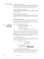
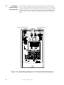
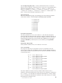
3.2
Switch
Functions
The Function of each switch in program mode is shown below:
No function in this mode
- Select operating mode
Address entry
keys are 0 to 9
Data entry keys
are 0 to 9 and A
to F
{
- Increment memory address
- Decrement memory address
- Once = First memory address
Twice = type any address
- Save data, go to next address
Figure 3-1: UNI•COM Keypad
3.3
Programming
Options
Primary phone number. (00-15)
The first sixteen addresses, 00-15, are factory set to 'F' (from 00_F to 15_F).
Programming is typically done as follows: If your phone # is 484-7161, type 4,
the display will read 00_4, press [ENTER/STORE] to save the entry to memory and
increment to the next address 01_F.
Enter the remaining numbers in their respective addresses as shown below:
4 8 4 7 1 6 1 F F F F F F F F F
00 01 02 03 04 05 06 07 08 09 10 11 12 13 14 15 .
18
Document # 50075 Rev B 3/13/95
Valid entries for both the primary and secondary phone numbers are 0 - F with the
numeric digits as dialed numbers and hexadecimal digits (A-F) representing the
following functions:
A= * on a Touchtone phone keypad
B= # on a Touchtone phone keypad
C= look for secondary dial tone for up to 2 seconds (then, dial anyway)
D= 3-second pause
E= 5-second pause
F= end of phone number (Note: F must be entered)
Primary Number Communication Format (16)
One location is needed to select the Communication Format to the primary phone
number. Address 16 is used for this purpose. The default (factory setting) for this
address is '0' and cannot be changed. The format is ADT FSK II.
Primary Number Account Code (17-19) Three locations at addresses 17-19 default
to all '0's. Valid entries are 0-9.
Primary Number 24 Hour Test Time (20-23).
Use military time when entering the 24 hour 'test' time. The 24 hour test report to
phone number 1 takes up four locations, from addresses 20-23. The default is 00:00
(12:00 midnight). The limits for each location are as follows: 20: enter 0, 1 or 2;
21: enter 0-9; 22 : enter 0-5; 23: enter 0-9. Note: Do not use A-F.
Primary Number 24/12 Hour Test Time Interval (24). The test report sent to the
Primary phone number may be sent every 12 or 24 hours. If the message is to be sent
every 24 hours, leave the factory default entry of zero. If 12 hour test report time is
needed, enter 1=12 hours.
Secondary Phone Number (25-40). Programming is similar to programming the
primary phone number located at addresses 00 - 15. The defaults are also all 'F's.
F
F
F
25 26 27
F
F
F
F
F
28
29
30
31
32 33
F
F
F
F
F
F
34
35
36
37
38 39 40
F
F
Secondary Number Communication Format (41). Programming is the same as the
primary number's Comm Format at address 16. Default entry is '0', ADT FSK II.
Secondary Number Account Code (42-44) is programmed in addresses 42 - 44 in
the same manner as the primary phone number Account Code. Default entries are all
'0s'.
Secondary Number 24-Hour Test Time (45-48) is programmed in addresses 4548 in the same manner as the primary number 24-Hour Test Time. Default is 00:00
(12:00 midnight).
Note: The UNI•COM automatically programs all of the event codes. See
Tables 3-2 and 3-3.
Document # 50075 Rev B 3/13/95
19
Secondary Number 24/12 Hour Test Time (49) The test message sent to the
Secondary phone number may be sent every 12 or 24 hours. If the message is to be
sent every 24 hours, leave the factory default entry of zero. If a 12 hour test report
time is needed, enter 1=12 hours.
Start Monitoring Address (50-51) is programmed to indicate the first group of
zones or points to be monitored and reported to the central station. Default is '01'.
Valid entries are '01, 02, 03 and 04'. See Table 3-1.
End Monitoring Address (52-53) is programmed to indicate the last group of zones
or points to be monitored and reported to the central station. Default is '01'. Valid
entries are '01, 02, 03 and 04'. See Table 3-1.
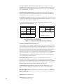
Use the Start and End Monitoring Address programming locations to set the
reporting range of the UNI•COM.
Zone Reporting (Factory Default)
Unimode 200
Unimode 4-16
Unimode II
2
1
1
START
Addr. 50-51
END
Addr. 52-53
01
01
01
01
01
02
1 = Reports status of 56 zones.
2 = Reports status of 120 zones.
Point Reporting
START
Adtr. 50-51
Unimode 200
01
END
Addr. 52-53
1
04
1
1 = Report status of 198 points
Note: For additional information on the starting and ending addresses,
refer to the host FACP Technical Manual.
Table 3-1: Start and End Monitoring Address
UNI•COM Communication Selection (54)
Leaving address 54 at '0' disables communications to the central station(s). Enter '1'
for zone reporting, receive only. Enter '2' for zone reporting, receive/transmit. Enter
'3' for point reporting, receive only. Enter '4' for point reporting, receive/transmit.
Note: Use receive only selections when using remote annunciators. Be certain to set
one of the annunciators for receive/transmit for EIA-485 communications bus
supervision. Use the receive/transmit entries when annunciators are not installed or
when the UNI•COM receive/transmit function is used to supervise the EIA-485
communication bus. For additional information on the receive/transmit function,
refer to annunciator technical manuals.
Backup Reporting (55) address 55 entry of '0' allows reports to be sent to
Secondary phone number as backup only. Leaving address 55 with the default
setting of '1' permits transmission to either the central station's Primary or Secondary
phone number. The report will be sent to the first available receiver. An entry of '2'
disables reports from being sent to the Secondary phone number.
Touchtone/Rotary Select (56) A '0' programmed in this address by the factory
triggers Touchtone dialing over both phone lines. Select '1' for rotary dialing.
Make Break Ratio (57) Use this address only if you have chosen '1' for address 56.
The make/break ratio is factory set to '0' which is 67/33, but may be changed to '1'
which is a 62/38 ratio.
Address (58) Leave default of 0.
Address (59) Leave default of 0.
20
Document # 50075 Rev B 3/13/95
AC Loss Reporting Delay (60) '1' is factory default which causes a 6 hour time
delay for AC loss reporting. Valid entries are 0 to 9 and A to F corresponding to the
following reporting delay times: '1' = 6 hour, '2' = 7 hours, '3' = 8 hours, '4' = 9
hours, '5' = 10 hours, '6' = 11 hours, '7' = 15 hours, '8' = 16 hours, '9' = 17 hours, 'A'
= 18 hours, 'B' = 19 hours, 'C' = 20 hours, 'D' = 21 hours, 'E' = 22 hours and 'F' = 23
hours. '0' entry causes immediate reporting of AC loss.
Host Panel ID (61)
Enter one of the following digits corresponding to the Control Panel in which the
UNI•COM is installed. A correct entry is essential for proper operation.
0 = Unimode 200
1 = Unimode 416
2 = Unimode II
3 = Do not use
4 = Do not use
5 = Do not use
6 = Do not use
7 = Do not use
8 = Do not use
9 = Do not use
Serviceman Code (62-65)
The factory default is 62=6, 63=3, 64=2 and 65=1. The code must be properly
entered to enable the following modes: program, walktest, troubleshoot and type. It
also enables the clear function. The code may be changed. If, however, the code is
changed and then forgotten, the factory default code of 6321 may be restored by
pressing the MODE key followed by A, A, 1, 2, 3 and then pressing [ENTER/
STORE].
Safety Delay Time (66-68)
Factory default is addresses 66=0, 67=0 and 68=0. Do not use.
User Codes (69-98)
Six 4-digit user codes may be programmed. The user is identified at the UCS
receiver by this 4-digit code. In addition, each user code may designate whether or
not the walktest events are transmitted to the UCS when the UNI•COM is used with
a Unimode 200 FACP.
69 - 72
73
74 - 77
78
79 - 82
83
84 - 87
88
89 - 92
93
94 - 97
98
= User 1 Walk Test Code
= User 1 Walk Test Transmit Enable
= User 2 Walk Test Code
= User 2 Walk Test Transmit Enable
= User 3 Walk Test Code
= User 3 Walk Test Transmit Enable
= User 4 Walk Test Code
= User 4 Walk Test Transmit Enable
= User 5 Walk Test Code
= User 5 Walk Test Transmit Enable
= User 6 Walk Test Code
= User 6 Walk Test Transmit Enable
For all User Walk Test Codes, the factory default of FFFF means no user is
identified. Altering the default entries causes the user to be identified. Valid entries
are 0 - 9 and A - F. For the Walk Test Transmit Enable addresses, a factory default
entry of '0' disables the transmission of walktest events, while an entry of '1' enables
the transmission of walktest events.
21
Document # 50075 Rev B 3/13/95
Programming Event Codes (99-168)
A description of the type of reports with reported 'event code' that are sent to the
central station appear in Tables 3-2 and 3-3. Entering a transmit selection of '0' will
cause the communicator to inhibit transmission of the report. Transmission of
reports to either or both central station phone numbers may be disabled.
Note the special 'System Abnormal Test Report' event code. This report was added
per new UL DACT requirements. This report is generated in place of the normal test
report when an alarm and/or trouble condition exists at the time the test report is
due to be sent.
Programming the Real-Time Clock
Entering an address greater than 172 will cause a display of the current time. On
initial power up, the clock will start running from the factory setting of 00:01
(military time). The far left digit will be flashing, indicating that this is the first digit
to be programmed.
Hours/Minutes
Select a digit then press [ENTER/STORE]. The digit 2nd from the left will start
flashing. Select a digit then press [ENTER/STORE]. Hours setting is complete.
With the digit 2nd from the right flashing, select a digit then press [ENTER/
STORE]. The digit on the far right will start flashing. Select a digit then press
[ENTER/STORE]. Minutes setting is complete.
End Programming
Exit Programming Mode by pressing MODE, followed by the 4-digit code
corresponding to an alternate mode of operation, then press [ENTER/STORE].
During Program Mode, if no key is pressed within 10 minutes, the UNI•COM will
revert to normal mode.
22
Document # 50075 Rev B 3/13/95
Address
99
Description
Setting
Event Codes
Primary # General Alarm Code
1
FA
100
Primary # Zone/Point Alarm Code
1
FA###*1ST
101
Primary # General Supervisory Code
1
SS
102
Primary # Zone/Point Supervisory Code
1
SS###*1ST
103
Primary # General System Fault Code
1
FT
104
Primary # AC Fault Code
1
AA
105
Primary # Zone/Point Fault Code
1
FT###*2ST
106
Primary # Supervisory Zone/Point Fault Code
1
ST###*2ST
107
Primary # Low Battery/Earth Fault Code
1
YT
108
Primary # Telco Primary Line Fault Code
1
LT1
109
Primary # Telco Secondary Line Fault Code
1
LT2
110
Primary # NAC Fault Code
1
UT*2ST
111
Primary # Comm. Trouble Primary # Code
1
LT1*8ST
112
Primary #Comm. Trouble Secondary # Code
1
LT2*8ST
113
Primary # 485 Communication Trouble Code
1
YC
114
Primary # Serviceman on Premises
1
id##SI
115
Walk Test Start
1
id#FM1
116
General Alarm Restore Code
1
FH
117
Primary # Zone/Point Alarm Restore Code
1
FR###
118
General Supervisory Restore Code
1
SR
119
Primary # Zone/Point Supervisory Restore Code
1
SR###
120
Primary # General Fault Restore Code
1
FJ
121
Primary # AC Fault Restore Code
1
AH
122
Primary # Alarm Zone/Point Fault Restore Code
1
FR###
123
Primary # Supervisory Zone/Point Fault Restore Code
1
SR###
124
Primary # Low Battery Fault Restore Code
1
YR
125
Primary #Telco Primary Line Fault Restore Code
1
LR1
126
Primary #Telco Secondary Line Fault Restore Code
1
LR2
127
Primary # NAC Fault Restore Code
1
UR
128
Primary # Comm. Trouble Primary # Restore Code
1
LR1
129
Primary # Comm. Trouble Secondary # Restore Code
1
LR2
130
Primary # 485 Communication Trouble Restore Code
1
YO
131
Primary # System Serviceman off Premises
1
id##SO
132
Primary # Walk Test End
1
id#FK1
133
Primary # Normal System 24 Hour Test
1
RP1
134
Primary # Abnormal System 24 Hour Test
1
RP5
135
Manual Test
1
RP1
Note: 1) Setting of 0 = do not transmit report to UCS
2) Setting of 1 = transmit report to UCS
3) Reports transmitted to the UCS for zone or point transmission use the following
convention: *1ST = Alarm Only, *2ST = Trouble Only, *3ST = Alarm & Trouble Simultaneously
Table 3-2: Event Codes, Primary Number
Document # 50075 Rev B 3/13/95
23
Address
Description
Setting
Event Codes
136
Secondary # General Alarm Code
1
FA
137
Secondary # Zone/Point Alarm Code
1
FA###*1ST
138
Secondary # General Supervisory Code
1
SS
139
Secondary # Zone/Point Supervisory Code
1
SS###*1ST
140
Secondary # General System Fault Code
1
FT
141
Secondary # AC Fault Code
1
AA
142
Secondary # Zone/Point Fault Code
1
FT###*2ST
143
Secondary # Supervisory Zone/Point Fault Code
1
ST###*2ST
144
Secondary # Low Battery/Earth Fault Code
1
YT
145
Secondary # Telco Primary Line Fault Code
1
LT1
146
Secondary # Telco Secondary Line Fault Code
1
LT2
147
Secondary # NAC Fault Code
1
UT*2ST
148
Secondary # Comm. Trouble Primary # Code
1
LT1*8ST
149
Secondary #Comm. Trouble Secondary # Code
1
LT2*8ST
150
Secondary # 485 Communication Trouble Code
1
YC
151
Secondary # Serviceman on Premises
1
id##SI
152
Walk Test Start
1
id#FM1
153
General Alarm Restore Code
1
FH
154
Secondary # Zone/Point Alarm Restore Code
1
FR###
155
General Supervisory Restore Code
1
SR
156
Secondary # Zone/Point Supervisory Restore Code
1
SR###
157
Secondary # General Fault Restore Code
1
FJ
158
Secondary # AC Fault Restore Code
1
AH
159
Secondary # Alarm Zone/Point Fault Restore Code
1
FR###
160
Secondary # Supervisory Zone/Point Fault Restore Code
1
SR###
161
Secondary # Low Battery Fault Restore Code
1
YR
162
Secondary #Telco Primary Line Fault Restore Code
1
LR1
163
Secondary #Telco Secondary Line Fault Restore Code
1
LR2
164
Secondary # NAC Fault Restore Code
1
UR
165
Secondary # Comm. Trouble Primary # Restore Code
1
LR1
166
Secondary # Comm. Trouble Secondary # Restore Code
1
LR2
167
Secondary # 485 Communication Trouble Restore Code
1
YO
168
Secondary # System Serviceman off Premises
1
id##SO
169
Secondary # Walk Test End
1
id#FK1
170
Secondary # Normal System 24 Hour Test
1
RP1
171
Secondary # Abnormal System 24 Hour Test
1
RP5
172
Manual Test
1
RP1
Note: 1) Setting of 0 = do not transmit report to UCS
2) Setting of 1 = transmit report to UCS
3) Reports transmitted to the UCS for zone or point transmission use the following
convention: *1ST = Alarm Only, *2ST = Trouble Only, *3ST = Alarm & Trouble simultaneously
Table 3-3: Event Codes, Secondary Number
24
Document # 50075 Rev B 3/13/95
4.0 Operating Instructions
4.1
Normal Mode
The UNI•COM has six Modes of operation; Normal, Program, Walktest,
Troubleshoot, Type and Lamp Test. Upon initial power up, the system will be in
Normal Mode. This section discusses operation of the UNI•COM in the Normal
Mode.
4.1.1 Keys: Below is a description of the function keys in Normal Mode:
MODE
Pressing the Mode Key followed by a valid 4-digit numerical code and [ENTER/
STORE] selects one of the six modes of operation.
☛ To enter normal mode from any other mode press MODE then
6676 [ENTER/STORE]. 6676 spells NORM on a
Touch-Tone® phone.
TEST
CLEAR
If the Test Key is pressed three times in rapid succession the UNI•COM will transmit
a manual test message to both central stations.
The Clear function will cause the UNI•COM to:
• cease transmissions
• clear any active or pending transmissions
• reset and return to normal system processing
To perform the Clear function, first press the MODE key, enter a valid serviceman
code and then press the [ENTER/STORE] key. Next press the CLEAR key
followed by 2, 5, 3, 2, then press the [ENTER/STORE] key.
Document # 50075 Rev B 3/13/95
25
1st EVENT
DOWN ARROW
UP ARROW
[ENTER/STORE]
This key along with the UP Arrow and DOWN Arrow keys, are used to display
UNI•COM fault conditions. Press the 1st EVENT key at any time to display the first
event that occurred.
Use the DOWN Arrow key to view other UNI•COM fault events (older) that have
occurred and are active - not cleared yet.
Use the UP Arrow key to view other UNI•COM fault events (newer), that have
occurred and are active - not cleared yet.
See individual mode descriptions in other sections.
4.1.2 Displays: Four 7-segment red LED characters provide visual annunciation of
UNI•COM trouble conditions. A list of messages that may appear on the display in
normal mode is shown below:
PH_1
PH_2
no_1
no_2
Primary Number Communication Fault
Secondary Number Communication Fault
Primary Phone Line Fault
Secondary Phone Line Fault
Individual LEDs are provided for:
EIA-485—A yellow LED that turns on steady when a fault on the EIA-485 circuit is
detected.
Comm. Fail—This yellow LED turns on to indicate the loss of both telephone lines
or that the maximum number of attempts to communicate with both Central Stations
has been unsuccessful. Note: During a comm fail, the display will show either a PH1
and PH2 or no1 and no2.
Power On—A green LED that remains on while DC power is supplied to the
UNI•COM. If this indicator fails to light under normal conditions, service the system
immediately.
Kiss-Off —A green LED that blinks when the central station has acknowledged
receipt of each transmitted message.
Test—A green LED that turns on to indicate that a manual test message is being
transmitted.
Primary Line Active—A red LED that indicates the primary phone line is active.
Secondary Line Active—A red LED that indicates the secondary phone line is
active.
Modem —A green LED that stays on steady while communication to the UCS is
taking place.
26
Document # 50075 Rev B 3/13/95
Primary
Line
Primary Active
Secondary
Line
Modem
LED
Secondary
Active
LED
Kiss-Off
LED
Figure 4-1: UNI•COM Phone Connectors and LEDs
4.1.3 Normal Mode Operation: Normal mode is the standard mode of operation. In
this mode, the UNI•COM monitors host FACP status, power input, EIA-485
communications and telephone line voltage.
The four character 7-segment display is normally off and does not annunciate events
that are being transmitted. The display will only annunciate UNI•COM trouble
conditions in the normal mode.
The UNI•COM transmits zone/point and system status reports to a central station via
the public switched telephone network. Two supervised telephone line connections
are made to interface the UNI•COM to the telephone lines.
The UNI•COM supervises both telephone lines for proper voltage. A delay of two
minutes will occur before a fault in either phone line connection is reported as a
trouble. When a fault is detected, the 4 character display will show either 'no 1' or 'no
2' (depending upon which telephone line has the fault. 'no 1' = Primary Line, 'no 2' =
Secondary Line) and the trouble condition will be reported to the central station over
the remaining good phone line.
The UNI•COM comes with line seizure capability provided for both the primary and
secondary telephone line interfaces. Any time that the UNI•COM needs to make a
call to the central station, line seizure will disconnect any local premises phones
sharing the same telephone line.
All transmission to the central station will be sent over the Primary phone line. In the
event of noisy phone lines, transmissions will be sent over the backup Secondary
phone line.
Options exist to: (1) send reports to the secondary phone number as backup only, (2)
send reports to either the primary or secondary phone numbers or (3) send reports to
the primary phone number only. For additional information, refer to programming
address 55. If 10 total attempts to communicate are unsuccessful, the Communicator
Failure output will be turned on (TB3, terminal 2).
Document # 50075 Rev B 3/13/95
27
The UNI•COM meets NFPA 72 for Remote Station Protective Signaling Service and
central station Signaling Service reporting requirements for: (a) the type of signal (b)
condition and (c) location of the reporting premises.
Since higher priority events take precedence over lower priority events, the
UNI•COM will transmit higher priority events before sending the lower priority
events. Priorities are as follows:
Event Activations
1. General Alarm
2. Zone/Point Alarm #N
3. General Supervisory
4. Zone/Point Supervisory #N
5. General System Trouble
6. AC Power Loss
7. Zone/Point Trouble #N
8. Low Battery
9. Telco Primary Line Fault
10. Telco Secondary Line Fault
11. NAC Fault Code
12. Communication Trouble, Primary Number
13. Communication Trouble, Secondary Number
14. EIA-485 Communication Bus Trouble
15. Serviceman on Premises
16. Walktest Start
17. System Automatic Test Report
18. System Abnormal Automatic Test Report
19. Manual Activated Test Report
Event Restorals
20. General Restoral
21. Zone/Point Alarm #N Restoral
22. General Supervisory Restoral
23. Zone/Point Supervisory #N Restoral
24. General System Trouble Restoral
25. AC Power Loss Restoral
26. Zone/Point Trouble #N Restoral
27. Low Battery Restoral
28. Telco Primary Line Fault Restoral
29. Telco Secondary Line Fault Restoral
30. NAC Fault Code Restoral
31. Communication Trouble, Primary Number Restoral
32. Communication Trouble, Secondary Number Restoral
33. EIA-485 Communication Bus Trouble Restoral
34. Serviceman off Premises
35. Walktest End
Where #N represents the zone or device ID number.
Note: The Unimode 200 has a maximum capacity of 99 addressable smoke detectors
and 99 addressable modules. When the UNI•COM is programmed for point transmission, the reported range of addresses is 001 to 099 for detectors at addresses 01 to 99
and 101 to 199 for modules at addresses 01 to 99.
When using AIM modules with the Unimode II, the UNI•COM will report AIM devices
in up to 8 zones maximum.
28
Document # 50075 Rev B 3/13/95
The 'general' reports for general fire, general supervisory and general fault are
always transmitted (unless disabled). Zone or point information will follow the
general reports if enabled.
4.1.4 Key Report Descriptions
Serviceman on Premises
This report is generated any time that the serviceman enters a 4-digit code into the
UNI•COM that matches the entry programmed into addresses 62-65. The report
generated to the UCS receiver tells the central station that a serviceman is on the
premises and is about to perform some type of maintenance on the system.
The Serviceman Code must first be entered in order for the serviceman to gain
access to program, walktest, troubleshoot and type modes. The Serviceman Code
also enables the clear function.
To enter the Serviceman Code, press the MODE key followed by the correct 4-digit
code, then press the [ENTER/STORE] key. Once the [ENTER/STORE] key is
pressed, the UNI•COM transmits the serviceman on premises report to the UCS. At
this time, the UNI•COM continues to be fully capable of reporting system status to
the central station.
Once the Serviceman Code is correctly entered, the UNI•COM may be placed into
any mode by pressing the MODE key, entering the appropriate 4-digit code and then
pressing the [ENTER/STORE] key. While in any of the selected modes, the
UNI•COM is not capable of reporting system status to the central station. The
4-digit codes are as follows:
Program Mode
Walktest Mode
Troubleshoot Mode
Type Mode
Clear Function
7764
9255
8768
8973
2532
For additional information on the functionality of each mode, see the appropriate
sections.
Note: If the Serviceman Code is forgotten, the factory default code of 6321 may be
restored by pressing the MODE key followed by A, A, 1, 2, 3 and then pressing the
[ENTER/STORE] key.
The UNI•COM will also transmit the Serviceman on Premises Report when the
correct level one password is entered into the Unimode 200.
Serviceman off Premises Report
The serviceman off premises report is generated to indicate that the serviceman has
completed maintenance on the fire alarm system and is exiting the premises. This
report is transmitted by the UNI•COM by pressing the MODE key, entering the
digits 99 and then pressing the [ENTER/STORE] key.
System Test Report
The UNI•COM will transmit a test message to both central stations at programmed
intervals (typically every 24 hours). Should there exist an abnormal condition in the
fire alarm system (such as an alarm, trouble or supervisory condition) at the time
when the test report is due to be transmitted, the UNI•COM will report the 'system
abnormal test report.' If the system is normal, the report transmitted will be the
normal 'system test report.'
29
Document # 50075 Rev B 3/13/95
EIA-485 Communications Trouble Report
The UNI•COM supervises the integrity of the information received from the FACP
via the EIA-485 communications bus. Should the communications bus malfunction,
the UNI•COM transmits the report '485 comm trouble.' When the communications
bus returns to proper operation, the UNI•COM will report '485 comm trouble
restoral.' The EIA-485 communications bus is supervised when the UNI•COM is
configured for receive only or receive/transmit operation.
Manual Test Report
By pressing the TEST key three times in rapid succession, the UNI•COM will
transmit a manual test report to the UCS. The TEST key may be pressed at any
time. The Serviceman Code is not required.
Program settings for zone or point reporting must match in both the host FACP and
the UNI•COM. Refer to the Unimode 200 Technical Manual section on Level One
programming for instructions on setting the FACP for zone or point annunciation.
Refer to Section 3.3 of this manual for instructions on setting addresses 50 through
54 and 61. Also refer to Section 4.3 for a discussion of Type Mode.
Zone/Point Fire Alarm Report
The UNI•COM reports activated status of specific zones or points defined as fire
alarm. Fire alarm devices include smoke detectors, pull stations, waterflow devices,
heat sensors, etc. The report transmitted includes the fire alarm message and the
identity of the activated zone or point.
Note: Use the Type Mode to identify all supervisory devices installed in the system
to the UNI•COM. Refer to the Type Mode instructions in Section 4.3.
Zone/Point Supervisory Activation Report
The UNI•COM reports activated status of specific zones or points defined as
supervisory. The report transmitted includes the supervisory alarm message and the
identity of the activated zone or point.
General Fault Report
The general fault report is transmitted for most types of system trouble conditions
including the following:
• Zone/point trouble
✓ Maintenance alert
✓ Wrong device
✓ Improper device
✓ Improper address
✓ Auto-detector test failure
✓ No response
✓ Shorted or open initiating device circuit
• Main SLC loop fault
• Earth fault
• Reverse polarity/city box trouble
• Memory corruption
• Disabled point
• Off-line programming
• Annunciator trouble.
Note: When a zone or point is in trouble, transmitted messages include the specific
zone or point trouble report and the general fault report (unless disabled).
A general fault report is not sent for AC loss and EIA-485 failure. These trouble
conditions are transmitted as individual trouble reports.
30
Document # 50075 Rev B 3/13/95
Zone or Point Restoral Report
Zone or point restoral reports are not transmitted to the UCS unless the zone or
point is fully cleared of both alarm and trouble conditions.
Walktest Begin and End Reports
• Serviceman Walktest:
Once a correct Serviceman Code is entered, Walktest Mode may be entered. In
Walktest Mode, the serviceman has the option of transmitting all system walktest
activity to the UCS or not reporting the activity to the UCS. The begin and end
walktest messages identify the person walktesting the system as a serviceman
(User id7).
• User Walktest:
Once a correct User Code is entered, Walktest Mode may be entered at the host
FACP. In Walktest Mode, the user option of transmitting all system walktest
activity to the UCS or not reporting the activity to the UCS is determined by
program entries 69-98. The begin and end walktest messages identify the user
walktesting the system as user 1 through 6. Refer to Section 3.3 for programming
addresses 69-98.
4.2
Walktest Mode
When used with a Unimode 200 FACP, Walktest Mode allows the option of
transmitting all system activity during walktesting to a central station. It also
prevents unwanted signals from being transmitted to the central station that may
be interpreted as real fire alarm reports.
For Unimode II and Unimode 4-16 applications, placing the FACP into Walktest
Mode causes transmission of an EIA-485 bus failure message. Exiting Walktest
Mode at the FACP causes the UNI•COM to transmit a restoral of EIA-485 bus
message.
To perform a Walktest, first, enter the Serviceman Code into the UNI•COM by
pressing the MODE key, entering 9255 and then pressing the [ENTER/STORE]
key. Next, place the host FACP into Walktest Mode (refer to appropriate section
in the host FACP Technical Manual). Note that the Unimode 200 must be placed
into point reporting operation in order to transmit walktest reports.
The display will show the letter C as the left most character and a flashing zero as
the right character. If the [ENTER/STORE] key is pressed, system walktesting
will occur without transmitting the system activity to the central station. With the
zero flashing, if the digit 1 is pressed changing the right most character to 1, and
then the [ENTER/STORE] key is pressed, walktesting will occur with system
activity transmitted to the central station.
The UNI•COM will display 9256 if walktest data is not being transmitted to the
central station. If the UNI•COM is transmitting the walktest data, 9259 will be
displayed.
The clear function may be used while in the walktest mode to stop the UNI•COM
from completing transmissions of walktest data. Exiting walktest mode is not
possible as long as there is walktest data waiting to be transmitted.
If users are allowed to walktest a system, they must follow the same steps described above except they must first enter their User Code.
Document # 50075 Rev B 3/13/95
31
The UNI•COM will not transmit any system walktest data unless the UCS receiver
(central station) first acknowledges receipt of the Begin Walk Test report. This is
an added precaution to insure that the walktest data is not misinterpreted at the
central station as a live report.
Exit walktest mode by entering the Serviceman off Premises code or return to an
alternate mode by entering the appropriate 4-digit code for that mode. Users
should enter the Normal Mode by entering code 6676. Should no activity occur in
the system for one hour, the UNI•COM will automatically exit walktest mode and
report 'id0BE1'.
4.3
Type Mode
Type mode may be used for the following purposes:
•
•
•
•
•
Disable alarm reports by zone or point
Identify which zones or points in the system are supervisory points
Identify which zones or points are fire alarm points
Change NAC fault report to unique report versus zone/point fault
Bypass reports for alarm or trouble on a zone/point
To access Type Mode, enter a valid serviceman code and press the MODE key.
Next enter the 4-digit code 8973 and then press the [ENTER/STORE] key. The
UNI•COM will display three digits. For example the display may be as follows:
01
0
The characters to the left identify the zone or point number. In this example, 01
identifies zone 01 or point address 01. The character to the right (0 in this
example) identifies the type of zone or point as follows:
0 = Zone or point defined as fire alarm
1 = Disable zone or point report for alarm only, transmit zone or point
fault
2 = Zone or point defined as supervisory
3 = NAC fault to be reported as 'UT###'
4 = Bypass zone or point reports entirely. No transmission of zone/point
alarm or fault
Factory default is all zones or points set to '0' for fire alarm. To change the type
definition of the zone or point from the factory setting of '0', press the 1, 2, 3 or 4
keys. The digit entered will appear on the far right display. Next press the
[ENTER/STORE] key. This stores the entry into E 2 memory and increments to
the next higher address.
Use the UP, DOWN and 1st EVENT keys to move through the list of 120 zones
or 198 points (refer to Appendices A, B and C), similar to the method described in
the programming section of this manual.
For Unimode 200 applications, when the UNI•COM is programmed for point
reporting, detectors are reported as points 001 to 099 and modules are reported as
points 101 to 199.
To define all zones or points as fire alarm (return to original factory default
settings) enter zone or point 999 and then press the [ENTER/STORE] key. The
display will change to 01 0, indicating a return to the factory default settings.
32
Document # 50075 Rev B 3/13/95
4.3.1 Disabling of Zones or Points
This feature is primarily used when system points have been defined as remote
reset, acknowledge, silence or drill switches. Refer to the FACP Technical
Manual for additional information. Activation of remote switches appear as
alarms on the EIA-485 bus while in point type of annunciation. The UNI•COM
will report these points as fire alarm points unless disabled in the Type Mode.
Disabling of zones or points also prohibits the activation (shorted or alarm
activated condition) from being reported by the UNI•COM. Disabling of the zone
or point does not affect the reporting of the zone or point trouble condition.
4.3.2 Zone or Point Supervisory
Defining a zone or point as supervisory is required in order for the UNI•COM to
identify the correct report to transmit to the UCS. Follow the programming
instructions in the Unimode 200 manual to program a zone or point as supervisory. Next program the zone or point as a code 2 for supervisory.
Use the charts in Appendices C and D to enter point and zone definitions.
Note that while in Type Mode, the fire protection and reporting capabilities of the
UNI•COM remain inactive.
4.4
Troubleshoot
Mode
To access the Troubleshoot Mode, enter the correct Serviceman Code, then press
MODE 8768 and [ENTER/STORE].
☛
8768 spells TROU on a Touch-Tone® phone.
Once in this mode, the UNI•COM will continue to communicate any events not
yet acknowledged at the central station prior to entering Troubleshoot Mode.
The UP Arrow, DOWN Arrow and 1st EVENT keys do not function in this
mode.
Telephone Line Testing
Pressing C for touchtone dialing or D for rotary dialing, followed by [ENTER/
STORE] causes seizure of the Primary phone line which in turn lights the red LED
signifying Primary phone line active. After a delay of three seconds, the UNI•COM
goes off hook to acquire a dial tone.
The UNI•COM keypad may be used as a telephone touchpad for number dialing.
Once the first digit is pressed, the display will move the C or D character one
position to the left, while placing the digit to be dialed on the farthest right display
position. Continue to press the phone numbers to be dialed. Successive depressions
of the [ENTER/STORE] key hangs up and picks up the phone (places the phone on
or off the hook).
The secondary phone line may be tested by pressing the E key for touchtone dialing
or the F key for rotary dialing and then following the same procedure used for the
primary phone line.
Document # 50075 Rev B 3/13/95
33
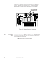
A handset may be temporarily connected across transformer T1 as indicated in
Figure 4-2. The handset, when connected across T1, may be used only as an
amplifier/speaker or telephone with the UNI•COM used for number dialing.
Both Primary and
Secondary Lines
Figure 4-2: Handset/Speaker Connection
4.5
Lamp Test
Mode
To perform a Lamp Test, press MODE then 5267 followed by [ENTER/STORE].
This will test all system LEDs. The LEDs will stay on for five seconds, then the
UNI•COM will return to normal mode.
☛ 5267 spells LAMP on a Touch-Tone® phone.
34
Document # 50075 Rev B 3/13/95
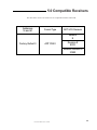
5.0 Compatible Receivers
The table below shows UL listed receivers compatible with the UNI•COM:
Addresses
16 and 41
Format Type
ADT UCS Receiver
Model #
E
Factory Default 0
ADT FSK II
Revision #
E913
Software Revision #
31893
Document # 50075 Rev B 3/13/95
35
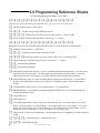
6.0 Programming Reference Sheets
--- To enter Programming, press Mode: 7 7 6 4, Enter
❑ ❑ ❑ ❑ ❑ ❑ ❑ ❑ ❑ ❑ ❑ ❑ ❑ ❑ ❑ ❑
00
01
02
03
04
05
06
07
08
09
10
11
12
13
14
15
Addresses 00 to 15 store the Primary Phone Number. Enter 'F' to represent the end of the number.
❑ Primary Comm Format: 0 = ADT FSK II.
❑ ❑ ❑ Primary Account Code: Valid keys are 0-9.
❑ ❑ ❑ ❑ Primary 24-Hour Test Time. Enter military time (i.e. 1400 for 2 PM).
❑ Primary Number Test Time Interval. Enter '0' for 24-hour; '1' - 12-hour.
❑ ❑ ❑ ❑ ❑ ❑ ❑ ❑ ❑ ❑ ❑ ❑ ❑ ❑ ❑ ❑
16
17
18
19
20
21
22
23
26
27
28
24
25
29
30
31
32
33
34
35
36
37
38
39
40
Addresses 25-40 store the Secondary Phone Number. Enter 'F' to represent the end of the number.
❑
❑
❑
❑
❑
❑
❑
41
Secondary Comm Format: 0 = ADT FSK II.
45
❑ ❑ Secondary Account Code: Valid keys are 0-9.
❑ ❑ ❑ Secondary 24-Hour Test Time. Enter military time (i.e. 1400 for 2 PM).
49
Secondary Number Test Time Interval. Enter '0' for 24-hour; '1' - 12-hour.
42
50
52
54
❑
55
43
44
46
47
❑
❑
51
53
58
Start Monitoring Address.
End Monitoring Address.
UNI•COM Communication Selection. Enter '0' to disable UNI•COM communication; '1' for zone reporting receive only communication; '2' for zone reporting receive/transmit communication; '3' for point
reporting receive only communication; '4' for point reporting receive/transmit communication.
Backup Reporting. Enter '0' to have secondary phone number act as backup only; '1' to have either
primary or secondary phone number receive reports; '2' to disable reports to the secondary phone
number.
❑
❑
56
57
❑
❑
❑
Touchtone/Rotary Select. Enter '0' for touchtone dialing; '1' for rotary dialing.
Make/Break Ratio. If rotary dialing is selected in Address 58; Enter '0' for a 67/73 make/break ratio; '1'
for a 62/38 make/break ratio.
58
Leave default of 0.
59
Leave default of 0.
60
AC Loss Reporting Delay. Enter '0' for no time delay after AC loss; '1' for 6 hour delay; '2' for 7 hour
delay; '3' for 8 hour delay; '4' for 9 hour delay; '5' for 10 hour delay; '6' for 11 hour delay; '7' for 15 hour
delay; '8' for 16 hour delay; '9' for 17 hour delay; 'A' for 18 hour delay; 'B' for 19 hour delay; 'C' for 20
hour delay; 'D' for 21 hour delay; 'E' for 22 hour delay; or 'F' for 23 hour delay.
❑
61
Host Panel ID. Enter '0' for Unimode 200; '1' for Unimode 416 or '2' for Unimode II; all other entries are
invalid.
❑ ❑ ❑ ❑ Serviceman Code.
❑ ❑ ❑ Leave default of '000'.
36
62
63
64
66
67
68
65
Valid entries are 0-9.
Document # 50075 Rev B 3/13/95
❑
❑
❑
❑
❑
❑
❑
❑
❑
❑
❑
❑
69
❑ ❑ ❑
73
User 1 Walk Test Transmit Enable: Enter '0' for no transmit of walktest events; '1' for transmit.
74
❑ ❑ ❑
78
User 2 Walk Test Transmit Enable: Enter '0' for no transmit of walktest events; '1' for transmit.
79
❑ ❑ ❑
83
User 3 Walk Test Transmit Enable: Enter '0' for no transmit of walktest events; '1' for transmit.
84
❑ ❑ ❑
88
User 4 Walk Test Transmit Enable: Enter '0' for no transmit of walktest events; '1' for transmit.
89
❑ ❑ ❑
93
User 5 Walk Test Transmit Enable: Enter '0' for no transmit of walktest events; '1' for transmit.
94
❑ ❑ ❑
98
User 6 Walk Test Transmit Enable: Enter '0' for no transmit of walktest events; '1' for transmit.
70
75
80
85
90
95
71
76
81
86
91
96
72
77
82
87
92
97
User 1 Walk Test Code. Valid entries are 0-9
User 2 Walk Test Code. Valid entries are 0-9
User 3 Walk Test Code. Valid entries are 0-9
User 4 Walk Test Code. Valid entries are 0-9
User 5 Walk Test Code. Valid entries are 0-9
User 6 Walk Test Code. Valid entries are 0-9
Document # 50075 Rev B 3/13/95
37
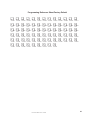
Programming Reference Sheet
❑
❑
❑
❑
❑
❑
99
112
125
138
151
164
38
❑
❑
❑
❑
❑
❑
100
113
126
139
152
165
❑
❑
❑
❑
❑
❑
101
114
127
140
153
166
❑
❑
❑
❑
❑
❑
102
115
128
141
154
167
❑
❑
❑
❑
❑
❑
103
116
129
142
155
168
❑
❑
❑
❑
❑
❑
104
117
130
143
156
169
❑
❑
❑
❑
❑
❑
105
118
131
144
157
170
❑
❑
❑
❑
❑
❑
Document # 50075 Rev B 3/13/95
106
119
132
145
158
171
❑
❑
❑
❑
❑
❑
107
120
133
146
159
172
❑
❑
❑
❑
❑
108
121
134
147
160
❑
❑
❑
❑
❑
109
122
135
148
161
❑
❑
❑
❑
❑
110
123
136
149
162
❑
❑
❑
❑
❑
111
124
137
150
163
Programming Reference Sheet Factory Default Settings
--- To enter Programming, press Mode: 7 7 6 4, Enter
F ❑
F
F
F
F
F ❑
F
F
F
F
F
F
F ❑
F
F
❑
❑
❑
❑
❑F ❑
❑
❑
❑
❑
❑
❑
❑
00
01
02
03
04
05
06
07
08
09
10
11
12
13
14
15
Addresses 00 to 15 store the Primary Phone Number. Enter 'F' to represent the end of the number.
0
❑
Primary Comm Format:0 = ADT FSK II.
0
0
0
❑
❑
❑
Primary Account Code.
0
0
0
0
❑
❑
❑
❑
Primary 24-Hour Test Time. 0000 = 12:00 midnight.
0
❑
Primary Number Test Time Interval. '0' for 24-hour.
F ❑
F
F
F
F ❑
F
F
F ❑
F ❑
F
F
F
F
F ❑
F
F
❑
❑
❑
❑
❑
❑
❑
❑
❑
❑
❑
16
17
18
19
20
21
22
23
26
27
28
24
25
29
30
31
32
33
34
35
36
37
38
39
40
Addresses 26-41 store the Secondary Phone Number. Enter 'F' to represent the end of the number.
0
❑
0
❑
0
❑
0
❑
0
❑
0
❑
0
❑
1
❑
0
❑
0
❑
0
❑
0
❑
1
❑
0
❑
6
❑
0
❑
41
Secondary Comm Format: 0 = ADT FSK II.
45
0
0
❑
❑
Secondary Account Code.
0 Secondary 24-Hour Test Time. 0000 = 12:00 midnight.
0
0
❑
❑
❑
49
Secondary Number Test Time Interval. '0' for 24-hour.
42
50
52
43
44
46
47
1
❑
1
❑
48
51
Start Monitoring Address
53
End Monitoring Address
54
UNI•COM Communication Selection. '0' for UNI•COM Communication disabled.
55
Backup Reporting. '1' reports to either Primary or Secondary Central Station.
56
Touchtone/Rotary Select. '0' for Touchtone.
57
Make/Break Ratio. '0' for 67/33 make/break ratio.
58
Leave default of zero.
59
Leave default of zero.
60
AC Loss reporting delay. '1' for 6 hour time delay.
61
Host PANEL ID. '0' for Unimode 200.
62
66
3
2
1
❑
❑
❑
Serviceman Code.
0
0
❑
❑
Leave default of '000'.
63
64
67
68
65
Factory default setting.
Document # 50075 Rev B 3/13/95
39
F
❑
0
❑
F
❑
0
❑
F
❑
0
❑
F
❑
0
❑
F
❑
0
❑
F
❑
0
❑
69
73
74
78
79
83
84
88
89
93
94
98
40
F
F
F
❑
❑
❑
70
71
72
User 1 Walktest Code. 'F' for no user identified.
User 1 Walktest Transmit Enable. '0' for no transmit.
F
F
F
❑
❑
❑
75
76
77
User 2 Walktest Code. 'F' for no user identified.
User 2 Walktest Transmit Enable. '0' for no transmit.
F
F
F
❑
❑
❑
80
81
82
User 3 Walktest Code. 'F' for no user identified.
User 3 Walktest Transmit Enable. '0' for no transmit.
F
F
F
❑
❑
❑
85
86
87
User 4 Walktest Code. 'F' for no user identified.
User 4 Walktest Transmit Enable. '0' for no transmit.
F
F
F
❑
❑
❑
90
91
92
User 5 Walktest Code. 'F' for no user identified.
User 5 Walktest Transmit Enable. '0' for no transmit.
F
F
F
❑
❑
❑
95
96
97
User 6 Walktest Code. 'F' for no user identified.
User 6 Walktest Transmit Enable. '0' for no transmit.
Document # 50075 Rev B 3/13/95
Programming Reference Sheet Factory Default
1
❑
1
❑
1
❑
1
❑
1
❑
1
❑
99
112
125
138
151
164
1
❑
1
❑
1
❑
1
❑
1
❑
1
❑
100
113
126
139
152
165
1
❑
1
❑
1
❑
1
❑
1
❑
1
❑
101
114
127
140
153
166
1
❑
1
❑
1
❑
1
❑
1
❑
1
❑
102
115
128
141
154
167
1
❑
1
❑
1
❑
1
❑
1
❑
1
❑
103
116
129
142
155
168
1
❑
1
❑
1
❑
1
❑
1
❑
1
❑
104
117
130
143
156
169
1
❑
1
❑
1
❑
1
❑
1
❑
1
❑
105
118
131
144
157
170
Document # 50075 Rev B 3/13/95
1
❑
1
❑
1
❑
1
❑
1
❑
1
❑
106
119
132
145
158
171
1
❑
1
❑
1
❑
1
❑
1
❑
❑1
107
120
133
146
159
1
❑
1
❑
1
❑
1
❑
1
❑
108
121
134
147
160
1
❑
1
❑
1
❑
1
❑
1
❑
109
122
135
148
161
1
❑
1
❑
1
❑
1
❑
1
❑
110
123
136
149
162
1
❑
1
❑
1
❑
1
❑
1
❑
111
124
137
150
163
172
41
Appendix A: Point Assignments (Unimode 200)
Point No.
01
02
03
04
05
06
07
08
09
10
11
12
13
14
15
16
17
18
19
20
21
22
23
24
25
26
27
28
29
30
31
32
33
34
35
36
37
38
39
40
41
42
43
44
45
46
47
48
49
50
Type of Device
(Detectors)
Point No.
51
52
53
54
55
56
57
58
59
60
61
62
63
64
65
66
67
68
69
70
71
72
73
74
75
76
77
78
79
80
81
82
83
84
85
86
87
88
89
90
91
92
93
94
95
96
97
98
99
100
Type of Device
(Detectors)
Not Used
Point No.
101
102
103
104
105
106
107
108
109
110
111
112
113
114
115
116
117
118
119
120
121
122
123
124
125
126
127
128
129
130
131
132
133
134
135
136
137
138
139
140
141
142
143
144
145
146
147
148
149
150
Type of Device
(Detectors)
Point No. Type of Device
(Detectors)
151
152
153
154
155
156
157
158
159
160
161
162
163
164
165
166
167
168
169
170
171
172
173
174
175
176
177
178
179
180
181
182
183
184
185
186
187
188
189
190
191
192
193
194
195
196
197
198
199
NOTE: The UNI•COM is capable of reporting 198 points when used with the Unimode 200. Use chart to carefully
identify supervisory points and remote switches in the system. Identify these points using Type Mode (refer to
Section 4.3 Type Mode).
42
Document # 50075 Rev B 3/13/95
Appendix B: Zone Assignments
(Unimode 200 & Unimode 4-16)
Zone No.
Zone Function
Zone No.
1
29
2
30
3
31
4
32
5
33
6
34
7
35
8
36
9
37
10
38
11
39
12
40
13
41
14
42
15
43
16
44
17
45
18
46
19
47
20
48
21
49
22
50
23
51
24
52
25
53
26
54
27
55
28
56
Zone Function
NOTE: The UNI•COM is capable of reporting 56 zones when used with the Unimode 200 or Unimode 4-16. Use
chart to carefully identify supervisory zones. Identify these zones using Type Mode (refer to Section 4.3 Type
Mode).
Document # 50075 Rev B 3/13/95
43
Appendix C: Zone Assignments (Unimode II)
Zone No.
Zone
Function
Zone No.
Zone
Function
Zone No.
1
41
81
2
42
82
3
43
83
4
44
84
5
45
85
6
46
86
7
47
87
8
48
88
9
49
89
10
50
90
11
51
91
12
52
92
13
53
93
14
54
94
15
55
95
16
56
96
17
57
97
18
58
98
19
59
99
20
60
100
21
61
101
22
62
102
23
63
103
24
64
104
25
65
105
26
66
106
27
67
107
28
68
108
29
69
109
30
70
110
31
71
111
32
72
112
33
73
113
34
74
114
35
75
115
36
76
116
37
77
117
38
78
118
39
79
119
40
80
120
Zone
Function
NOTE:Use chart to carefully identify supervisory points and remote switches in the system. Identify these 120 zones
using Type Mode (refer to Section 4.3 Type Mode).
44
Document # 50075 Rev B 3/13/95
Appendix D: Unimode 200
The UNI•COM is capable of reporting 198 points or 56 zones when used with the
Unimode 200.
The UNI•COM may be mounted in the Unimode 200 control panel or remotely in an
ADT-ABS8RF or ADT-UBS1F enclosure up to 6000 feet away from the control
panel. All power must be removed from the control panel before making any
connections to prevent circuit damage. The EIA-485 serial interface is connected
between the control panel and UNI•COM using twisted, shielded pair wire. Power
should be wired from the control panel's 24 VDC (nominal) filtered, non-resettable
output to TB1 on the UNI•COM if mounted remotely.
Figure D-1: ADT-UBS1F
UNI•COM mounting in Unimode 200
Remove all power from the Unimode 200 by disconnecting AC and batteries. Install the supplied standoffs (three nylon
and one aluminum standoff) in the appropriate holes located on the right side of the Unimode 200 main circuit board as
illustrated in Figure D-2. Position J10 located on the back of the UNI•COM over connector J16 which is located center
right on the main Unimode 200 circuit board, and carefully connect. Secure the UNI•COM to the aluminum standoff
with the screw provided.
The EIA-485 circuit and 24 VDC power are provided directly from connector J16 of the Unimode 200. Note: A 120 ohm
EOL resistor is not required on the UNI•COM EIA-485 terminals when it is installed inside the Unimode 200 cabinet.
The EOL resistor is required at the last device on the EIA-485 line external to the Unimode 200 panel.
Unimode 200
3/4" aluminum standoff
with nut required for
transient protection
UNI•COM
3/4" Nylon
Standoffs
Figure D-2: UNI•COM Mounting to Unimode 200
Document # 50075 Rev B 3/13/95
45
Supervised and Power
Limited EIA-485 and
power connections
+24 VDC
Nonresettable
Power
To
Phone
Lines
(Supervised)
Solid
Earth
Ground
Connection
Ferrite
Cores
P/N 29090
Install 120 ohm EOL
resistor (P/N: 71244)
on TB1 terminals 3
& 4 if last or only
device on EIA-485
line.
Unimode 200
Cabinet
UNI•COM in ADT-ABS8RF
(shown with cover removed)
Unimode 200
Notes:
1) This arrangement allows use of the UNI•COM simultaneously with the RTM-8F module.
2) Ferrite cores are recommended for all applications.
3) Recommended wire is 12 AWG to 18 AWG twisted pair.
4) Shielded wire is not required (unless mandated by local AHJ).
If shielded wire is used, connect only one end of shield:
a) shield may be connected to cabinet (earth ground) at fire alarm panel, or
b) shield may be connected to TB1 Terminal 5 (Shield) at UNI•COM as shown in
Figure D-3. NOTE: The shield end that is not connected should be insulated to prevent
accidental grounding. Do not connect both ends of shield under any circumstance
since a ground fault may result.
5) Conduit is recommended for external wire runs. Consult local building codes.
6) Connect Ground Strap (supplied with ADT-ABS8RF enclosure) from Earth Ground terminal on
UNI•COM to a solid building earth ground. Conduit alone will not provide a reliable earth ground.
7) UNI•COM may be located up to 6000 feet away from the host control panel.
8) Refer to Specifications for power requirements.
Figure D-3: External UNI•COM Mounting in ADT-ABS8RF
46
Document # 50075 Rev B 3/13/95
Appendix E: Unimode 4-16
The UNI•COM is capable of reporting a maximum of 56 zones when used with the Unimode 4-16.
The UNI•COM reports alarms and troubles on inputs and reports only troubles on outputs. Beware of
'gaps' in the reporting of input circuits. The gaps depend upon the mounting location and FACP
configuration. The Unimode 4-16 has a maximum of 16 inputs.
The UNI•COM must be mounted remotely in an ADT-ABS8RF or ADT-UBS1F enclosure and may be
placed up to 6000 feet away from the control panel. All power must be removed from the control panel
before making any connections to prevent circuit damage. The EIA-485 serial interface is connected
between the control panel and UNI•COM using twisted, shielded pair wire. Power should be wired
from the control panel's main power supply (MPS-24BPCA) 24 VDC (nominal) filtered power supply
output to TB1 on the UNI•COM.
Figure E-1: ADT-ABS8RF
Supervised and Power
Limited EIA-485 and
power connections
To Phone
Lines
(Supervised)
Solid Earth
Ground
Connection
P/N 29090
Unimode 4-16
Install 120 ohm
EOL resistor (P/N:
71244) on TB1
terminals 3 & 4 if
last or only device
on EIA-485 line.
UNI•COM in ADT-ABS8RF
Notes:
(Shown with cover removed)
2) Ferrite cores are recommended for all applications.
3) Recommended wire is 12 AWG to 18 AWG twisted pair.
4) Shielded wire is not required (unless mandated by local AHJ).
If shielded wire is used, connect only one end of shield:
a) shield may be connected to cabinet (earth ground) at fire alarm panel, or
b) shield may be connected to TB1 Terminal 5 (Shield) at UNI•COM as shown in
Figure E-2. NOTE: The shield end that is not connected should be insulated to prevent
accidental grounding. Do not connect both ends of shield under any circumstance
since a ground fault may result.
5) Conduit is recommended for external wire runs. Consult local building codes.
6) Connect Ground Strap (supplied with ADT-ABS8RF enclosure) from Earth Ground terminal on
UNI•COM to a solid building earth ground. Conduit alone will not provide a reliable earth ground.
7) UNI•COM may be located up to 6000 feet away from the host control panel.
8) Refer to Specifications for power requirements.
Figure E-2: External UNI•COM Mounting in ADT-ABS8RF
Document # 50075 Rev B 3/13/95
47
Cut jumper JP1
to make output
nonresettable for
use with UNI•COM
-
+
Filtered, regulated,
resettable, powerlimited 24 VDC
Figure E-3: MPS-24BPCA Connection to UNI•COM
48
Document # 50075 Rev B 3/13/95
Appendix F: Unimode II
The UNI•COM is capable of reporting 120 zones when used with the Unimode II. The UNI•COM
reports alarms and troubles on inputs but reports only troubles on outputs. Beware of 'gaps' in the
reporting of input circuits. The gaps depend upon the mounting location and the Unimode II system
configuration. AIM modules are reported as a maximum of 8 zones.
The UNI•COM may be mounted in the Unimode II control panel or remotely in an ADT-ABS8RF
or ADT-UBS1F enclosure up to 6000 feet away from the control panel. All power must be removed
from the control panel before making any connections to prevent circuit damage. The EIA-485
serial interface is connected between the control panel and UNI•COM using twisted, shielded pair
wire. Power should be wired from the control panel's main power supply 24 VDC (nominal) filtered,
non-resettable output to TB1 on the UNI•COM.
Figure F-1: ADT-ABS8RF
UNI•COM mounting in Unimode II
Remove all power from the Unimode II by disconnecting AC and batteries. Install the three supplied nylon support
posts for the top and bottom left of the UNI•COM, one aluminum/nylon and one aluminum standoff in the CHS-4 chassis
slot in which the UNI•COM is to be installed (refer to Figure F-2). Position the UNI•COM on the standoffs and secure
on aluminum standoff with a #6-32 screw.
Connect the communication line between the EIA-485 terminal block on the CPU-5000 and TB-1 terminals 3 and 4 on
the UNI•COM being certain to observe polarity (refer to Figure F-3). Recommended wire is 12 AWG to 18 AWG twisted
pair. If no other devices are connected to the EIA-485, install a 120 ohm EOL resistor across UNI•COM TB1 terminals
3 and 4.
Connect the supplied Ground Strap from the UNI•COM Earth Ground terminal on TB3 to the CHS-4 chassis. Connect
24 VDC filtered, regulated power to TB1 terminals 1 and 2 on the UNI•COM (refer to Figure F-4).
UNI•COM
Nylon Support Posts
Ground Strap
CHS-4
CPU-5000
Nylon and
Aluminum Standoff
Aluminum
Standoff and
Screw
Figure F-2: UNI•COM Mounting in CHS-4
Document # 50075 Rev B 3/13/95
49
EIA-485 (Supervised and
Power Limited)
+
TB1
Terminal 3 RS+
Terminal 4 RS-
CPU-5000
Install 120
ohm EOL
resistor (P/
N:71244)
across
terminals 3 &
4 if last or only
device on EIA485 line. Note
that Terminals
6 & 7 are not
used at this
time.
UNI•COM
Figure F-3: EIA-485 Connection
50
Document # 50075 Rev B 3/13/95
Power (Supervised and
Power Limited)
TB1-1 +
TB1-2 -
TB3-3 +
- TB3-4
UNI•COM
MPS-24A
Power (Supervised and
Power Limited)
TB1-1 +
TB1-2 -
TB2-1+
- TB2-2
Cut jumper JP1
to make output
nonresettable for
use with UNI•COM
UNI•COM
MPS-24B
Figure F-4: 24 VDC Power Connection to UNI•COM
Document # 50075 Rev B 3/13/95
51
NOTES
52
Document # 50075 Rev B 3/13/95
NOTES
Document # 50075 Rev B 3/13/95
53
NOTES
54
Document # 50075 Rev B 3/13/95
Document # 50075 Rev B 3/13/95
55