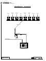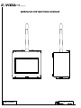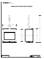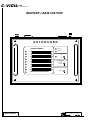
1
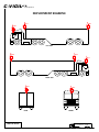
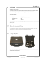
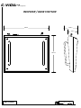
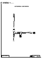
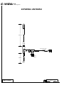
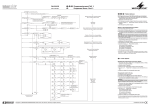
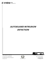
C-VIGILL T D
: transport
AUTOGUARD INTRUSION
DETECTION
C-VIGIL Ltd
Registered in England & Wales:
Company Registration No. 04407624
Digital House, Peak Business Park, Foxwood Rd,
Chesterfield, Derbyshire, S41 9RF, UK.
VAT Registration No. GB 804 6004 68
ISO 9001:2008 Registration No. GB 2001654
www.cvigil.co.uk
C-VIGIL Ltd : transport
Swbd: +44 (0)8432 898 464
T: +44 (0)1246 269 469
F: +44 (0)1246 351 288
E: [email protected]
C-VIGILL T D
: transport
AUTOGUARD INTRUSION DETECTION
INTRODUCTION
High Risk Areas
Strategically placed wireless PIR motion detectors will alert the driver to possible intrusions without exposing him/her to
unnecessary risks
Port Area Security
Detect unwanted guests who try to gain access to your vehicle. Protect the relatively exposed trailer section.
Stowaway Prevention
Detect personnel approaching the vehicle with the intent to gain un-authorised access.
AUTOGUARD COMPRISES
•
Receiver / Base Station
•
8 Wireless PIR Detector Heads
•
Hard Sided Carry / Storage Case
•
External Antenna + Coax Cable
•
Mounting Tripods + Mag Base Mounts + Bungee Cord Mounts
•
User Manual
•
Mains Cable
C-VIGIL Ltd
C-VIGILL T D
: transport
DEPLOYMENT EXAMPLE
PIR 2
PIR 3
PIR 1
LEFT SIDE
PIR 6
PIR 5
PIR 4
RIGHT SIDE
PIR 7
REAR
NOT TO SCALE
PIR 8
FRONT
C-VIGIL Ltd
C-VIGILL T D
: transport
AutoGuard – Transport
CAB RIGHT
TRAILER RIGHT
FRONT
TRAILER RIGHT
REAR
CAB LEFT
TRAILER LEFT
FRONT
TRAILER LEFT
REAR
TRAILER REAR
CAB FRONT
PIR 1
PIR 2
PIR 3
PIR 4
PIR 5
PIR 6
PIR 7
PIR 8
Wireless Link
External Antenna
Mag Mount
Mains (charging)
RB
Base Station (in cab)
NOT TO SCALE
C-VIGIL Ltd
AUTOGUARD
Wireless Intrusion Detection System
User Manual - Page 2
AUTOGUARD
AUTOGUARD
Wireless Intrusion Detection System
User Manual
Intrusion Detection
www.cvigil.co.uk
C-VIGIL Ltd : transport
[email protected]
User Manual - Page 3
AUTOGUARD
Contents
SYSTEM DESCRIPTION .............................................................................................. 4
1.1
1.1.1
1.1.2
Detector Heads ................................................................................................................................... 4
General .......................................................................................................................................... 4
Detection Zones ................................................................................................................................ 5
1.2
Receiver / Base Station ........................................................................................................................ 6
1.2.1
General ...................................................................................................................................... 6
1.2.2
Alarm Outputs ............................................................................................................................. 6
1.2.3
System Code Transmission & Settings ............................................................................................... 7
1.2.4
Storage / Carry Case ................................................................................................................... 7
2.
OPERATION & DEPLOYMENT............................................................................... 8
2.1
General ............................................................................................................................................ 8
2.2
Detector Deployment ......................................................................................................................... 8
2.3
Receiver / Base Station Deployment .................................................................................................... 9
3.
DETECTOR BATTERY ENDURANCE ........................................................................ 9
Intrusion Detection
www.cvigil.co.uk
C-VIGIL Ltd : transport
[email protected]
User Manual - Page 4
AUTOGUARD
System Description
1.1
Detector Heads
1.1.1
General
Each detector head is a self-contained battery powered unit capable
of transmitting a coded alarm signal to the central monitoring
station. Any number of similarly coded heads or a repeater may be
deployed in up to eight separate zones.
Each sensor is capable of continuous operation for up to about 10
years (see Section 3. for battery endurance). Alarm response is by
way of passive infra red detection (PIR). The active alarmed area is a
30m beam detection zone from the sensor faceplate. This gives
excellent selective positioning control when deploying the units, for
example, running along a ship’s open decks, across a hatch entrance
way, gangway access point.
The units have a protective faceplate that also acts as an on/off switch.
Note: Environmental conditions may reduce effective operating distance
Once the heads are activated they are ready for immediate deployment as and when
required. Optimum detection is achieved when mounted approximately 2m above the
ground and positioned so that target movement will be across the zone rather than towards
or away from the unit.
It is important to avoid situations where two or more heads can trigger simultaneously as
this can corrupt the coded transmission to the base station. Once deployed the detection
zones can be “walk-tested” using the base station on battery power.
Note:
Once activated the head has a reset time of approximately 5 seconds after
movement has ceased.
Detector heads should be tested/activated periodically otherwise after prolonged periods of
inactivity the heads ‘go to sleep’ and will require the cover to be replaced to reset the
detector.
Intrusion Detection
www.cvigil.co.uk
C-VIGIL Ltd : transport
[email protected]
User Manual - Page 5
AUTOGUARD
1.1.2
Detection Zones
The detection zones are indicated in the diagrams below: -
2m
2.4m
30m
Detection Zone – Side View
3m
3m
30m
Detection Zone – Plan View
Intrusion Detection
www.cvigil.co.uk
C-VIGIL Ltd : transport
[email protected]
User Manual - Page 6
AUTOGUARD
1.2
Receiver / Base Station
1.2.1
General
The unit is lightweight and is intended for mains operation but also contains an internal
rechargeable battery capable of providing up to 36 hours of portable / standby use, “walktesting” for example. The battery is charged automatically during mains operation.
The base station can also be powered by an external 12V DC supply, the internal battery is
charged during this mode of operation (this facility is available to special order only).
A single on/off switch, this illuminates the yellow power indicator next to the switch.
The alarm sounder may be set to one of three modes ‘Off’, ‘Steady’ or ‘Pulse’ by way of the
audible alarm switch.
The nine bank LED display indicates an alarm condition by the individual zone numbers and
remains illuminated until the reset switch is activated. The incoming alarm signal also triggers
the sounder depending on the mode setting.
The reset switch is used to extinguish any illuminated zone LEDs as and when required. It will
also reset the low battery warning. The sounder will operate again if a new alarm is received
from a zone already illuminated on the LED display prior to reset.
The low Battery indicator illuminates on receipt of low battery warning transmitted by any of
the detection heads. (See notes on Detector Head Batteries).
1.2.2
Alarm Outputs
On the rear of the unit either a two pole terminal is fitted for providing a single common
output for all alarms or a 15 pin socket is fitted for additionally supplying individual outputs
for all eight alarms. The individual outputs can be used, for example, to position CCTV
cameras, while the common alarm is suitable for activating existing alarm systems.
Intrusion Detection
www.cvigil.co.uk
C-VIGIL Ltd : transport
[email protected]
User Manual - Page 7
AUTOGUARD
Base Station Alarm Outputs:-
A universally normally open contact available via the two pole terminal posts. This output
closes momentarily on receipt of a valid alarm signal from any of the 8 zones.
15 pin “D” Connector
Pin 1 – 7
Alarms 1 – 7
Pin 9
Output common for all alarms
Pin 8 & 10 – 14
N/C
Pin 15
Alarm 8
These outputs are ‘clean’, normally open giving momentary closure when a signal is received
from any zone
1.2.3
System Code Transmission & Settings
On activation each detection head transmits two separate signal codes back to the base
station. A third low battery code will be transmitted when required.
1.2.4
Storage / Carry Case
When not in use the system may be stored in a hard sided case for protection and ease of
transportation and deployment.
Intrusion Detection
www.cvigil.co.uk
C-VIGIL Ltd : transport
[email protected]
User Manual - Page 8
AUTOGUARD
2.
Operation & Deployment
2.1
General
Autoguard is a completely self-contained portable intruder detection system demanding
minimal skill during deployment and subsequent operation. Capable of monitoring up to
eight separate zones from a single monitoring unit it provides invaluable protection for a vast
range of security operations where mobility and versatility are the prime operational
requirements.
The system is supplied in a robust protective case complete with the following items: -
•
A battery / mains operated base station monitoring unit complete with alarm
outputs and integrated radio receiver.
•
Eight coded battery powered detection heads, for portable deployment on the ship
as required, capable of transmitting a radio signal back to the base station giving
location number of alarmed area
•
2.2
Operating instructions
Detector Deployment
1.
Remove the detector from its carry case
2.
Install the detector(s) in their final locations:
i. On a suitable bracket on the ship’s structure / side rails
ii. Free standing on its tripod base
iii. Attached to a convenient point by the bungee cords
3.
Remove the protective cover from the detector
Intrusion Detection
www.cvigil.co.uk
C-VIGIL Ltd : transport
[email protected]
User Manual - Page 9
AUTOGUARD
2.3
Receiver / Base Station Deployment
•
Power-up the base station by connecting the mains lead into the back of the unit
•
Switch ‘On’ the base station, the mains LED will glow yellow indicating power is
supplied to the unit (The charging LED may also glow if the internal rechargeable
batteries are at a certain voltage level. This LED indicates the unit is also being
charged; this will not effect the application.
•
With all or several detector units deployed, you may have several alarms showing,
this is normal because they would have been activated during installation.
Activating the reset button should clear these alarms, if not, check the detectors
set-up.
•
It is always required that a ‘walk-test’ be carried out on each detector location.
•
Once the base station is activated you can choose whether you want the activation
audio able or silent. In either mode the alarm LED will illuminate on alarm
•
The base station can be operated for up to 36 hours on its own internal
rechargeable batteries, although it is normal to run the system from mains.
3.
Detector Battery Endurance
No Alarms
1 Alarm / 24h
2 Alarms / 24h
10 Alarms / 24h
24 Alarms / 24h
Days
Years
5606
15.36
Days
Years
5461
14.96
Days
Years
5323
14.58
Days
Years
4431
12.14
Days
Years
3443
9.43
Intrusion Detection
www.cvigil.co.uk
C-VIGIL Ltd : transport
[email protected]
User Manual - Page 10
AUTOGUARD
AUTOGUARD
Wireless Intrusion Detection System
Schematics
Intrusion Detection
www.cvigil.co.uk
C-VIGIL Ltd : transport
[email protected]
C-VIGILL T D
: transport
DEPLOYMENT EXAMPLE
PIR 2
PIR 3
PIR 1
LEFT SIDE
PIR 6
PIR 5
PIR 4
RIGHT SIDE
PIR 7
REAR
NOT TO SCALE
PIR 8
FRONT
C-VIGIL Ltd
C-VIGILL T D
: transport
AutoGuard – Transport
CAB RIGHT
TRAILER RIGHT
FRONT
TRAILER RIGHT
REAR
CAB LEFT
TRAILER LEFT
FRONT
TRAILER LEFT
REAR
TRAILER REAR
CAB FRONT
PIR 1
PIR 2
PIR 3
PIR 4
PIR 5
PIR 6
PIR 7
PIR 8
Wireless Link
External Antenna
Mag Mount
Mains (charging)
RB
Base Station (in cab)
NOT TO SCALE
C-VIGIL Ltd
C-VIGILL T D
: transport
WIRELESS PIR MOTION SENSOR
NOT TO SCALE
C-VIGIL Ltd
C-VIGILL T D
: transport
WIRELESS PIR MOTION SENSOR
68mm
132mm
66mm
NOT TO SCALE
57mm
93mm
C-VIGIL Ltd
C-VIGILL T D
: transport
RECEIVER / BASE STATION
Rd
Bk
AUTOGUARD
ALARM CHANNELS
1
Mains
Battery
2
Off
3
On
4
Audible Alarm
Off
Constant
Pulsed
5
6
7
8
Reset
DETECTORS LOW BATTERY
NOT TO SCALE
C-VIGIL Ltd
C-VIGILL T D
: transport
RECEIVER / BASE STATION
260mm
110mm
76mm
Rd
Bk
260mm
NOT TO SCALE
C-VIGIL Ltd
C-VIGILL T D
: transport
EXTERNAL ANTENNA
Coax Cable to Base
Station
NOT TO SCALE
C-VIGIL Ltd
C-VIGILL T D
: transport
EXTERNAL ANTENNA
130mm
Coax Cable to Base
Station
10mm
Nylock
66mm
NOT TO SCALE
C-VIGIL Ltd