1
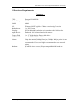
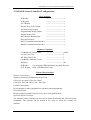
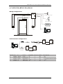
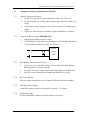
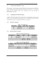
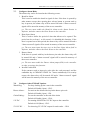
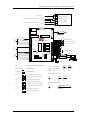
Access Control System
EXP-06E
Single Door Access Controller
Installation and Operation
Instructions
Version 6.6
Revision 2003-5
EXP-06E Access Control System Installation Instruction
1.
INTRODUCTION
The ACS Access Control System is a powerful software based time recording, access
control and integrated security system designed to meet the most demanding access
control and point monitoring applications. Programming the system is done from a
cost effective IBM compatible microcomputer. Cards can be added or deleted in
seconds. All events can be archived for future reference and report generation.
The system can control doors, turnstiles, gates and more. It can monitor different
sensors such as intrusion motion detectors, door contacts, low temperature and can
activate cameras or lighting controls automatically, unattended. The ACS access
Control System provides user with much more than basic access control features. In
its standard configuration, the system not only provides sophisticated features for the
most demanding installation, but also complies with functionality and budgetary
requirements.
For standalone system, the access controller contains the keypad with programmable
functions. It can be used to define the cardholder information, time schedule for
access of user, holiday definition and record printing.
For PC network system, RS485 and communication interface card can be used to link
up the controllers to PC for direct accessing the update records.
Satcom Systems (International) Co., Ltd.
2
EXP-06E Access Control System Installation Instruction
2. Hardware Requirements
Computer :
CPU:
Hard disk space:
RAM:
OS:
Motherboard:
Display:
Input Device:
Floppy Disk:
CD-ROM Drive:
Printer:
Modem:
Pentium III 800MHz
500MB
64MB
Windows 98SE English / Chinese version (big5 version)
1 x RS232 port
SVGA 800x600 resolution color monitor with 16 bits color
Enhanced 101 keyboard and serial mouse
1 x 3.5” high-density floppy disk drive
1 x 8X CD-ROW Drive
24pin dot matrix (360dpi)/laser jet (300dpi). Inkjet printer is not
recommended. Users are highly recommended to use network
printer.
(For Wide Area Access) Hayse compatible 9600 baud rate.
Satcom Systems (International) Co., Ltd.
3
EXP-06E Access Control System Installation Instruction
3. EXP-06E Access Controller Configuration
I/O Capacities
IN Reader
----------------------------- 1
IN Keypad
----------------------------- 1
OUT Reader
----------------------------- 1
Electric Door Lock Output
----------------------------- 1
Auxiliary Relay Output
---------------------------- 1
Programmable Relay Output
---------------------------- 1
Parallel Printer Port
----------------------------- 1
Door Release Button Input
----------------------------- 1
Door Sensor Input
----------------------------- 1
RS232 Communication Interface ----------------------------- 1
RS485 Communication Interface ----------------------------- 1
Memory Capacities
Cardholders & Transactions
--------------------------- 16,000
Access Time Zone
--------------------------- 9
Pin Entry Time Zone
--------------------------- 3
Cardholder Authority Levels
--------------------------- 3
Holidays
--------------------------- 100
IN Reader
: Can be using LED Indication Lamp with Keypad
OUT Reader : Only LED Indication Lamp
System Characteristics
Multiple Technologies:
Supports Proximity and Magnetic Stripe Card
Selectable Acceptance Entrance Mode:
Card Only, Pin Code Only, Card + Pin Code
Complete Standalone:
Do not depend on other equipment for operation and programming.
Distributed Data:
Memory and processing located at every door. No degraded mode.
Optional Remote Terminal:
The optional remote terminal can be used for alarm monitoring and selected system
commands. The terminal can be located a few away or across the country via
modems.
Satcom Systems (International) Co., Ltd.
4
EXP-06E Access Control System Installation Instruction
4. CONFIGURARTION DIAGRAM
Wiring Configurations
C
B
A
A
A
A
EXP-06E
Auxiliary Relay Output
D
B
A
Alarm Relay Output
Parallel Printer
Entry
Exit
Host PC
Communication Configurations
E
Modem
Modem
Telephone Line
E
E
D
EXP-06E
D
D
RS232/RS485
Converter
EXP-06E
EXP-06E
D
32
1
EXP-06E
Host PC
RS232/RS485
Converter
Wire Label
A
B
C
D
E
From
EXP-06E
EXP-06E
EXP-06E
EXP-06E
EXP-06E
To
I/O Device
Reader
Keypad
PC
PC
1
Function
Control
Reader Comm.
Keypad Comm.
RS485 Comm.
RS232 Comm.
Satcom Systems (International) Co., Ltd.
32
Gauge(AWG) No. of Pair Shielded
24
1
Yes
24
4
Yes
24
4
Yes
24/22
2
Yes
24
2
Yes
Max. Length (M)
150
150
8 /150 (EXP-02 Extension Module)
1,200
16
5
EXP-06E Access Control System Installation Instruction
6. User Card Operation Procedures
6.1 Present Card Only
Place the card on the present card area. If the entrance is permitted, the proximity card
reader will sound a long "beep". Then the door lock will be released with a certain
time defined by supervisor. If prohibited, by "INVALID CARD" (Invalid Card
Number) or "WRONG ACCESS" (Invalid Anti-Passback) or "WRONG LEVEL"
(Invalid Access Time Zone) the proximity card reader will sound three sort
"beep-beep-beep".
6.2 Present Card with Pin Code
If the entrance need to input pin code after the card presented, the proximity card
reader's LED light will hold on 5 seconds to green color, user should key in 4 digits
pin code through the keypad. If the pin code is correct, the proximity card reader will
sound a long "beep". Then the door lock will be released with a certain time defined
by supervisor. Otherwise, the proximity card reader will sound three sort
"beep-beep-beep" for "WRONG CODE". For security reason, this operation can only
be tried 7 times. After than access right will be terminated for this card only.
6.3 Single Pin Code Entry Only
At this operation mode, users can key in the card number through keypad instead of
card
operation. Press "#" key will enable this function if this operation is set. If
user are allowed to entry the area by using Key Operation, the proximity card reader's
LED light will hold on 5 seconds to green color, user should key in 8 digits card
number assigned to the user. If the entrance is permitted, the proximity card reader
will sound a long "beep". Then the door lock will be released with a certain time
defined by supervisor. If prohibited, the proximity card reader will sound three sort
"beep-beep-beep".
6.4 Double Pin Code Entry Only
At this operation mode, user can key in the card number and pin code through keypad
instead of card operation. Press "#" key will enable this function if this operation is set.
If user are allowed to entry the area by using Key Operation, the proximity card
reader's LED light will hold on 5 seconds to green color, user should key in 8 digits
card number assigned to the user. If the card number is "ACCEPTED", the proximity
card reader's LED light should still hold more 5 seconds to key in 4 digits pin code. If
the pin code is correct, the proximity card reader will sound a long "beep". Then the
door lock will be released with a certain time defined by supervisor. If prohibited, the
Satcom Systems (International) Co., Ltd.
6
EXP-06E Access Control System Installation Instruction
proximity card reader will sound three sort " beep-beep-beep". For security reason,
the key Operation can only be tried 3 times. After than the Key Operation will be
terminated for this card only. Card operations then need to reset the termination.
6.5 Turn ON/OFF Control Relay by User Card with Pin Code
At this function mode, user must press "9" button in the keypad and hold it on and
present the card. If this card user's "AUTHORIZE LEVEL" is allowed to operate this
function, the proximity card reader's LED light will hold on 5 seconds to green color,
user should release key "9" button in the keypad and key in 4 digits the current used
pin code. If the card user is authorized and the pin code is correct, the proximity card
reader will sound a long "beep". Then the control relay will be turn ON or OFF.
Otherwise, the proximity card reader will sound three sort "beep-beep-beep" for
"INVALID AUTHORIZE LEVEL" OR "WRONG PIN CODE".
6.6 Change Pin Code by User Card with Current Pin Code
User can change the pin code that is related to the card issued to him. At this function
mode, user must press "0" button in the keypad and hold it on and present the card. If
the information of the card is stored at data memory of the controller. the proximity
card reader's LED light will hold on 5 seconds to green color, user should release key
"0" button in the keypad and key in 4 digits the current used pin code. If the key in pin
code is correct, the proximity card reader's LED should change to red color; user then
is to ready key in 4 digits new pin code. The proximity card reader's LED should
change to green color and user should key in same 4 digits new pin codes again for
verification. If the verification pin code is correct the proximity card reader will sound
a long "beep". Then the new pin code is started to active. Otherwise, the proximity
card reader will sound three sort "beep-beep-beep" for incorrect verification by "NOT
MATCH NEW PIN CODE". Then user is still using the old pin code.
6.7 Turn ON/OFF Control Relay by User Card with Duress Pin Code
If duress alarm function interfaced with alarm control panel, user can use this function
for under duress active.
At this function mode, user must press "9" button in the keypad and hold it on and
present the card. If this card user's "AUTHORIZE LEVEL" is allowed to operate this
function, the proximity card reader's LED light will hold on 5 seconds to green color,
user should release key "9" button in the keypad and key in 4 digits "Duress Pin Code.
If the card user is authorized and the duress pin code is correct, the proximity card
reader will sound a long "beep". Then the control relay will be turn ON or OFF and at
the same time access controller send out a duress alarm signal to alarm control panel.
Satcom Systems (International) Co., Ltd.
7
EXP-06E Access Control System Installation Instruction
Otherwise, the proximity card reader will sound three sort "beep-beep-beep" for
rejected active by "INVALID AUTHORIZE LEVEL" OR "WRONG PIN CODE".
Remark : Duress Pin Code is the current user pin code add one.
i.e. If the user pin code is 0001 then the duress pin code should be 0002.
6.8 Present Card with Duress Pin Code
If duress alarm function interfaced with alarm control panel, user can use this function
for under duress access. At this function mode, user should place the card on the
present card area, the proximity card reader's LED light will hold on 5 seconds to
green color, user should key in "Duress Pin Code" through the keypad. If the duress
pin code is correct, the proximity card reader will sound a long "beep". Then the door
lock will be released and at the same time access controller send out a duress alarm
signal to alarm control panel. Otherwise, the proximity card reader will sound three
sort "beep-beep-beep" for rejected access by "WRONG CODE".
Remark : Duress Pin Code is the current user pin code add one.
i.e. If the user pin code is 0001 then the duress pin code should be 0002.
i.e. If the user pin code is 9999 then the duress pin code should be 0000.
6.9 Double Pin Code Entry for Duress Pin Code
If duress alarm function interfaced with alarm control panel, user can use this function
for under duress access. At this function mode, user should key in the card number
and duress pin code through keypad instead of card operation. Press "#" key will
enable this function if this operation is set. If user are allowed to entry the area by
using Key Operation, the proximity card reader's LED light will hold on 5 seconds to
green color, user should key in 8 digits card number assigned to the user. If the card
number is "ACCEPTED", the proximity card reader's LED light should still hold
more 5 seconds to key in 4 digits "Duress Pin Code". If the pin code is correct, the
proximity card reader will sound a long "beep". Then the door lock will be released
and at the same time access controller send out a duress alarm signal to alarm control
panel. Otherwise, the proximity card reader will sound three sort " beep-beep-beep"
for rejected access by " WRONG CODE".
Remark : Duress Pin Code is the current user pin code add one.
i.e. If the user pin code is 0001 then the duress pin code should be 0002.
i.e. If the user pin code is 9999 then the duress pin code should be 0000.
Satcom Systems (International) Co., Ltd.
8
EXP-06E Access Control System Installation Instruction
7. INSTALLATION OF EXP-06E
7.1
Overview of EXP-06E
The EXP-06E has two-reader port and one keypad port, capable of handling three
relay outputs. The EXP-06E is housed in a 16 AWG metal wall-mounted cabinet. The
static RAM consumes minimal power for storing memory and data. The EXP-06E is
compatible with PC using Access Control System.
The EXP-06E offers software- controlled features such as Time Zone, Key Zone,
Holiday, Programmable Zone, Cardholders database and Anti-passback control.
The EXP-06E has two types of battery backup: onboard memory and operational
power. The operational power battery, known as the Advanced Power Supply(APS),
gives the EXP-06E internal power fail capability.
7.2
Physical Requirement
External devices connect to the EXP-06E via ports located on the right and left sides
of the Connectors and the device types are listed in Table 1.1. See Figure 1.1.
The following table is External Devices Connectors
Devices
In Reader
Out Reader
Keypad
Alarm Relay Output
Programmable Relay Output
Door Lock Relay Output
Door Sensor
Door Release Button
RS-232 Communication Port
RS-485 Communication Port
Power Supply DC2, COM
Event Printer Port
Satcom Systems (International) Co., Ltd.
Connectors
C1 (1-7)
C3 (1-7)
C2 (2-8)
C4 (R,Q)
C4 (P,O)
C4 (N,M)
C4 (L,K)
C4 (J,K)
C4 (G,H,I)
C4 (E,F)
C4 (A,B)
C5 PRINTER
9
EXP-06E Access Control System Installation Instruction
7.3
Equipment Wiring /requirement of EXP-06E
7.3.1
Readers (In/Out) & Keypad
1. Do NOT wiring with any other high power cable. E.g. 220V AC
2. Do NOT install near switches that produce large amount of spark. E.g.
Light.
3. Choose linear power supply for the readers instead of switching power
supply.
4. Follow the cable wiring specification by the manufacturer of readers.
7.3.2
Door Lock Relay Output (IMPORTANT)
1. Install diode parallel to the door lock.
2. ATTENEION: It may affect the performance of EXP-06E when diode
is not installed parallel to the lock. See Figure 1.2.
Electric
Door
Lock
7.3.3
Door Release Button & Door Sensor
1.
Connect one end of the Door Sensor and one end of the Door Release
Button together to connector pin K.
2.
Use AWG 24 wire to connect the Door Release Button with EXP-06E.
3.
Do NOT connect Door Release Button and EXP-06E over 50ft.
7.3.4
RS-232 & RS-485
Must use shield twisted pair wire to connect EXP-06E with host computer.
7.3.5
Switching Power Supply
Connect the polarity (positive & negative) correctly.
7.3.6
See figure
Event Printer Port
Use DOT-MATRIX Printer to print the update event report.
Satcom Systems (International) Co., Ltd.
10
EXP-06E Access Control System Installation Instruction
7.4
Connecting the EXP-06E to a host
The connector – G, H, I connects a single EXP-06E to the host computer via RS-232C
format. Multiple EXP-06E communicates with host from connector – F, E via RS-485
format. But the EXP-06E chain must communicate with host through an
RS232/RS-485 converter.
7.4.1
Configuring the EXP-06E Jumpers
Configure EXP-06E jumpers JP4 & JP5 for the host communication format you are
using. For host communication using the RS-232C communication using the RS-485
communication protocol, set jumpers JP4 & JP5 to 1-2 position.
7.4.2
RS-232C Connection
Table – Pin connection
EXP-06E Pin
Signal
DB25 DB9 Host Signal
Ground
7
5
Ground
I
Data Transmit
3
2
Data Receive
H
Data Receive
2
3
Data Transmit
G
7.4.3
Remote Modem Connection
EXP-06E Pin
I
H
G
Table – Pin connection (RS-232)
Signal
DB25
DB9
Ground
7
5
Data Transmit
2
3
Data Receive
3
2
4&5 Sort
4&6 Sort
6&20 Sort 7&8 Sort
Table – Pin connection (RS-485)
Signal
DB25 (485 Converter) DB9 (Modem)
Ground
7
5
Data Transmit
3
3
Data Receive
2
2
4&5 Sort
4&6 Sort
6&20 Sort
7&8 Sort
Satcom Systems (International) Co., Ltd.
Host Signal
Ground
Data Receive
Data Transmit
Host Signal
Ground
Data Receive
Data Transmit
11
EXP-06E Access Control System Installation Instruction
7.4.4
Configuring the RS-485 Interface Card
RS-485 Interface Card is used to communicate PC and EXP-06E via RS-485 format.
Make sure there are no other devices using COM3 and I/O address (03E8-03EF) in
the PC before installation. If there is a device using COM3 already, readdress the
port and address of this device.
1.
2.
3.
7.4.5
Install the interface card into an ISA expansion slot on the PC motherboard.
The interface card connects totally up to 9 different input ports. To enable input
port, short the related jumper. See the table – Pin connection.
Connect the RS-485 output on EXP-06E to the appropriate pin of the chosen
input port in DB25. See the table – Pin connection.
Configure the RS-485 Converter (Model:ic485Ip-1F)
Table – Pin connection
EXP-06E Pin
Converter
2,4 Sort
E
1,3 Sort
F
7.5 Connection with Advanced Power Supply (Option)
The Power Supply Board provides uninterrupted power backup of EXP-06E. Refer to
the table – External Device Connectors, the 220V AC filter protects the EXP-06E,
preventing an unstable power e.g. Spark; affect the performance as IN/OUT card
readers. One the left side of the PS-01, 12V DC input is designed to control power for
electric strike door lock. Therefore, the activities of the electric strike door lock (lock /
unlock) can be controlled by the EXP-06E. A separate power supply for the electric
strike door lock is designed to prevent the lock drain the controller backup battery
quickly when AC powers failure.
7.6.
Configure Relay Output
To change the configuration of the Door Lock Relay Output, Programmable Relay
Output and Alarm Relay Output to Normal Open or Normal Close, follow the jumper
setting shown in the table – External Device Connectors (JP2, JP3, JP7)
Satcom Systems (International) Co., Ltd.
12
EXP-06E Access Control System Installation Instruction
7.7.
Configure Alarm Relay
The alarm relay can be activated at the following events:
1. Break In Alarm
This is used to enable the break in signal of door. if the door is opened by
other matters except door opening door release button or present card or
key-in process, the alarm relay will be turned ON and a "alarm occurred"
signal will be stored in memory of the access controller.
p.s. The user must enable the Break In Alarm at the Alarm Section in
Software, and also connect the Door Sensor to the controller.
2. Door Open Alarm
This is used to define the period of door that allows to be opened. The
period can be set from 1 to 99 second. 0 is disabled this function. If the
door is opened out of this period, the alarm relay will be turned ON and a
"alarm occurred" signal will be stored in memory of the access controller.
p.s. The user must input the time (sec) at the Door Open Alarm field in
Software, and also connect the Door Sensor to the controller.
3. Duress Alarm
If the door is opened with key in the duress pin code, the alarm relay will
be turned ON and a "alarm occurred" signal will be stored in memory of
the access controller.
p.s. The user must enable the Duress Alarm jumper(JP8) in the controller
in order to activate this function.
4. Invalid Card & PIN
If the entrance need to input pin code after the card presented, and the
cardholder key in "WRONG CODE" for 7 times continuously. For security
reason, the alarm relay will be turned ON and a "alarm occurred" signal
will be stored in memory of the access controller.
7.8.
Configure Other EXP-06E Options
Watch Dog
:
For keep looking up the event in the controller.
Default is Disable (Open) – JP15.
Duress Alarm :
For activate the alarm when keyin the duress pin code.
Default is Disable (Open) – JP8.
Chain Ending :
For set the controller as the end of the chain
Default is Disable (Open) – JP18.
12V DC
:
For turning ON/OFF the 12V DC input to the controller.
Default is ON (Short) – JP12.
5V/12V DC :
For choosing 5V/12V DC output for card reader. – JP14
Satcom Systems (International) Co., Ltd.
13
EXP-06E Access Control System Installation Instruction
8. Specification
8.1 EXP-06E Access Controller
CPU
Memory
Clock & Data Memory back-up battery
:
:
:
Communication Interface
Data Transfer Rate (Local & Remote)
Input Voltage
:
:
:
Power Consumption
:
Temperature
Humidity
:
:
Satcom Systems (International) Co., Ltd.
8031
32KB
Non-charge
1 month backup during power failure
RS232 and RS485Converter type
9,600 bps
AC 220 - 240V / 50 - 60Hz
12V AC / DC
Approx. 8W - AC 220V - 240V
Approx. 0.8A - 12V AC / DC
0 - 40 degree Celsius
20% - 80% RH
14
EXP-06E Access Control System Installation Instruction
FG
AC220V Input
A C -L
Model : SFLA-030-2L
12V B (-)
A C -N
Switching Power Supply
12V A (+)
DC2
12V (-)
COM
12V (+)
DC1
Connected to EXP-06 Controller Board
12V Output for Electric Lock (2 am p.)
Program
Chip
Battery
JP1
C5
RAM
1
DATA 1 / STROBE
DATA 0 / DATA
Alarm Relay Output
BEEPER
EXP-06E Controller Board
JP7
LED
GND
7 1
+VDC
JP3
KEY PAD
I/O 1
JP2
C2
JP14
8 1
DATA 1 / STROBE
DATA 0 / DATA
BEEPER
LED
JP5
3 1
C3
NO T USE/ CARD PRESENT
JP4
3 1
232
GND
75176
7
+VDC
JP15
JP8
JP18
JP12
Program m able Relay Output
C4
A B C DE F G H I J K L M N O PQ R
NO T USE/ CARD PRESENT
C1
READER
(IN)
Parallel Printer
I/O 2
CPU
READER
(OUT)
DC1 +12V(2A)
DC2 -12V (1A)
Door Lock Relay Output
Door Sensor
Door Release Button
5
2
RS232
9 pin
3
5
25 pin
6
RS485
DC2
IBM Com patible PC
COM
JP1
JP4 & JP5
JP4 & JP5
JP16
Sort Using Battery for Data Mem ory
3
1
3
1
Enable RS485
W atch Dog
Duress Alarm
12VDC
Sort
Active
Disable
-ON
O pen
Deactive
Enable
-O FF
Enable RS232
5VDC Output for Reader Supply
12VDC Output for Reader Supply
JP2
JP15
JP8
JP18
JP12
Door Lock Relay Output (NO)
RS232 Com m unication
C4
G
H
I
9 PIN
3
2
5
25 PIN
2
3
7
Door Lock Relay Output (NC)
JP3
Program m able Relay Output (NO)
Program m able Relay Output (NC)
JP7
Alarm Relay Output (NO)
RS485 Com m unication
C4
E
F
RS485/RS232 Converter
RS485 (-)
RS485 (+)
Alarm Relay Output (NC)
Satcom Systems (International) Co., Ltd.
15