1
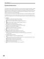
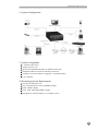
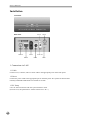
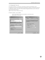
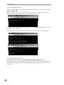
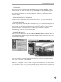
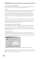
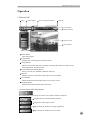
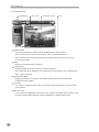
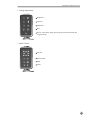
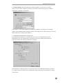
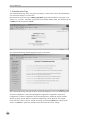
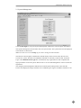
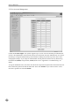
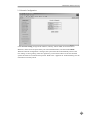
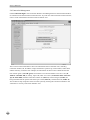
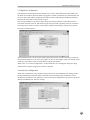
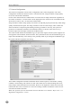
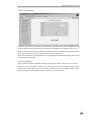
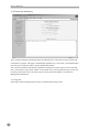
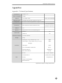
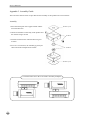
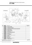
Manual Ver 1.2
CA70-0002
CAUTION
RISK OF ELECTRIC SHOCK
DO NOT OPEN
CAUTION: TO REDUCE THE RISK OF ELECTRIC SHOCK,
DO NOT REMOVE COVER (OR BACK).
NO USER-SERVICEABLE PARTS INSIDE.
REFER SERVICING TO QUALIFIED
SERVICE PERSONNEL.
The lightning flash with arrowhead symbol, within an equilateral triangle, is
intended to alert the user to the presence of uninsulated “dangerous voltage”
within the product’s enclosure that may be of sufficient magnitude to
constitute a risk of electric shock.
The exclamation point within an equilateral triangle is intended to alert the
user to the presence of important operating and maintenance (servicing)
instructions in the literature accompanying the appliance.
COMPLIANCE NOTICE OF FCC:
THIS EQUIPMENT HAS BEEN TESTED AND FOUND TO COMPLY WITH THE LIMITS
FOR A CLASS A DIGITAL DEVICE, PURSUANT TO PART 15 OF THE FCC RULES.
THESE LIMITS ARE DESIGNED TO PROVIDE REASONABLE PROTECTION AGAINST
HARMFUL INTERFERENCE WHEN THE EQUIPMENT IS OPERATED IN A
COMMERCIAL ENVIRONMENT. THIS EQUIPMENT GENERATES, USES, AND CAN
RADIATE RADIO FREQUENCY ENERGY AND IF NOT INSTALLED AND USED IN
ACCORDANCE WITH THE INSTRUCTION MANUAL, MAY CAUSE HARMFUL
INTERFERENCE TO RADIO COMMUNICATIONS. OPERATION OF THIS EQUIPMENT
IN A RESIDENTIAL AREA IS LIKELY TO CAUSE HARMFUL INTERFERENCE, IN
WHICH CASE USERS WILL BE REQUIRED TO CORRECT THE INTERFERENCE AT
THEIR OWN EXPENSE.
CAUTION: CHANGES OR MODIFICATIONS NOT EXPRESSLY APPROVED BY THE
PARTY RESPONSIBLE FOR COMPLIANCE COULD VOID THE USER’S AUTHORITY
TO OPERATE THE EQUIPMENT.
THIS CLASS OF DIGITAL APPARATUS MEETS ALL REQUIREMENTS OF THE
CANADIAN INTERFERENCE-CAUSING EQUIPMENT REGULATIONS.
THE INFORMATION IN THIS MANUAL IS BELIEVED TO BE ACCURATE AS OF THE DATE OF
PUBLICATION. IDIS, CO., IS NOT RESPONSIBLE FOR ANY PROBLEMS RESULTING FROM THE
USE THEREOF. THE INFORMATION CONTAINED HEREIN IS SUBJECT TO CHANGE WITHOUT
NOTICE. REVISIONS OR NEW EDITIONS TO THIS PUBLICATION MAY BE ISSUED TO
INCORPORATE SUCH CHANGES.
I M P O RTANT SAFEGUARDS
1. Read Instructions
All the safety and operating instructions should be read
before the appliance is operated.
2. Retain Instructions
The safety and operating instructions should be retained
for future reference.
3. Cleaning
Unplug this equipment from the wall outlet before
cleaning it. Do not use liquid aerosol cleaners. Use a damp
soft cloth for cleaning.
10. Lightning
For added protection for this equipment during a lightning
storm or when it is left unattended and unused for long
periods of time, unplug it from the wall outlet and
disconnect the antenna or cable system. This will prevent
damage to the equipment due to lightning and power-line
surges.
11. Overloading
Do not overload wall outlets and extension cords as this
can result in the risk of fire or electric shock.
4. Attachments
Never add any attachments and/or equipment without the
approval of the manufacturer as such additions may result
in the risk of fire, electric shock or other personal injury.
12. Objects and Liquids
Never push objects of any kind through openings of this
equipment as they may touch dangerous voltage points or
short-out parts that could result in a fire or electric shock.
Never spill liquid of any kind on the equipment.
5. Water and/or Moisture
Do not use this equipment near water or in contact with
water.
13. Servicing
Do not attempt to service this equipment yourself. Refer
all servicing to qualified service personnel.
6. Accessories
Do not place this equipment on an unstable cart, stand or
table. The equipment may fall, causing serious injury to a
child or adult, and serious damage to the equipment. Wall
or shelf mounting should follow the manufacturer’s
instructions and a mounting kit approved by the
manufacturer should be used.
14. Damage Requiring Service
Unplug equipment from the wall outlet and refer servicing
to qualified service personnel under the following
conditions:
A. When the power-supply cord or the plug has been
damaged.
B. If liquid is spilled, or objects have fallen into the
equipment.
C. If the equipment has been exposed to rain or water.
D. If the equipment does not operate normally by
following the operating instructions, adjust only those
controls that are covered by the operating instructions as
an improper adjustment of other controls may result in
damage and will often require extensive work by a
qualified technician to restore the equipment to its normal
operation.
E. If the equipment has been dropped, or the cabinet
damaged.
F. When the equipment exhibits a distinct change in
performance, indicating a need for service.
This equipment and cart combination should be moved
with care. Quick stops, excessive force, and uneven
surfaces may cause the equipment and cart combination to
overturn.
7. Ventilation
Slots and openings in the cabinet and the back or bottom
are provided for ventilation, to ensure reliable operation of
the equipment, and to protect it from overheating. These
openings must not be blocked or covered. Do not block
these openings or allow them to be blocked by placing the
equipment on a bed, sofa, rug, or bookcase. Ensure that
there is adequate ventilation and that the manufacturer’s
instructions have been adhered to.
8. Power Sources
This equipment should be operated only from the type of
power source indicated on the marking label. If you are
not sure of the type of power, please consult your
equipment dealer or local power company.
9. Power Cords
Do not allow anything to rest on the power cord. Do not
locate this equipment where the cord will be damaged by
persons walking on it.
15. Replacement Parts
When replacement parts are required, be sure the service
technician has used replacement parts specified by the
manufacturer or that have the same characteristics as the
original part. Unauthorized substitutions may result in fire,
electric shock, or other hazards.
16. Safety Check
Upon completion of any service or repairs to this
equipment, ask the service technician to perform safety
checks to determine that the equipment is in proper
operating condition.
17. Field Installation
This installation should be made by a qualified service
person and should conform to all local codes.
Table of Contents
Product Information
05
Installation
06
1. Connection via LAN
06
2. Connection via Dial-up Modem
10
Operation
11
1. Browser 100
11
2. Administration Page
16
Appendixes
25
1. Technical Specifications
25
2. Assembly Guide
26
3. Troubleshooting
27
User’s Manual
Product Information
This product provides an advanced solution for retrieving video over computer networks, including
the Internet. It grabs composite video images from one video input, compresses them, and then
transmits them over computer networks or telephone lines at speeds up to 30 frames per second. In
addition to video access, this product provides audio and alarm information from the remote site.
There are one sensor input and one alarm input.
The user can listen in on the remote site with the audio input. This product is capable of remotely
controlling pan, tilt, zoom, and focusing cameras. All of features are accessible through Internet
web browsers, allowing users to access and control their systems any time from virtually anywhere.
1. Features
A) Monitor live video images transmitted in real-time
Remote monitoring up to 30fps live video images
Low network bandwidth requirement: 3KB per image typical
Three-levels of input resolution: 640x480, 320x240, 160x120
Four-levels of image compression
B) Simultaneous video and audio signal transmission
Monitor voices and background sounds via one audio input
C) Supports various network environments
Ethernet or Fast Ethernet interface for Internet
Modem interface for standard telephone lines
D) Easy software upgrades from anywhere
Upgrade software at remote sites using a web browser
E) E-mail transmission ensures important events are not missed
Video can be transmitted to assigned e-mail addresses whenever a sensor detects
an input signal
F) Additional convenient features
Remote multiplexer control through RS485 interface
Note: This function requires an additional software for each supported multiplexer model.
Autosensing for the video format (NTSC/PAL)
One digital sensor input and one alarm output
RS485 interface for Pan/Tilt/Zoom/Focus control
One video loop-through terminal
Each function can be set remotely using a web browser
4
1-Channel Video Server
2. System Configuration
3. System Components
1-Channel Video Server
Adapter (12VDC, 1A)
Browser100 Installation Diskette for Modem Connection
MINIDIN-8/DB-9 Converter for Modem Connection
Assembly Accessaries (Refer to Appendix 2. Assembly Guide.)
User’s Manual
4. Monitoring System Requirements
OS: Microsoft Windows 98
CPU: Intel Pentium II Celeron 266MHz or higher
RAM: 32MB or higher
VGA: AGP, Video RAM 4MB or higher
Web Browser: Internet Explorer 5.0 or higher version
5
User’s Manual
Installation
Front Panel
Audio In
Back Panel
Video Out
I/O Port
Network
Video In
Power Jack
RS232
Reset
1. Connection via LAN
1.1 Cable
Connect LAN, a camera, and/or a sensor cable to the appropriate ports on the back panel.
1.2 Power
Connect the power cable to the appropriate port on the back panel. The system has been booted
normally if POWER LED blinks once within 10 seconds.
1.3 PC Setup
Use a PC that can network with the system without a router.
(From now on, this particular PC will be referred to as “PC”.)
6
1-Channel Video Server
1.4 Configuring PC Network
Under Start in Windows, go to Settings, Control Panel, and then Network Setting. In the
Configuration tab, select the TCP/IP and then click Properties. Modify your network configuration
as shown below. Make a note of the existing network configuration values of your PC since you
need to restore them in Step 1.8.
Note: You may need to reboot after this step.
Example) IP Address: 192.168.1.150
(In fact, fourth address may be any value from 1 to 254, except 129.)
Subnet Mask: 255.255.255.0
7
User’s Manual
1.5 Verifying Network Setup
Under Start in Windows, go to Programs, then choose MS-DOS Prompt. Enter the ping command
(ping -t 192.168.1.129).
Note: By sending a packet to the specified address and waiting for a reply, the PING (Packet
Internet Groper) can determine whether a specific IP address is accessible.
If the ping utility returns “Reply from 192.168.1.129...”, it means that the address has been set and
communication is established.
If the ping utility continually returns “Request timed out”, go back to Step 1.2 and try again.
1.6 Administrator Configuration
Start your Web browser and enter “http://192.168.1.129/admin_login.html” in the
location/address field. The Administrator Login Page will appear. Enter a login ID and password.
The default ID is admin, and the password is 12345. Refer to the “Administration Page” section
for details.
8
1-Channel Video Server
1.7 Configuration
Move to the Network Config menu in the Administration Page and modify IP address, gateway,
and subnet mask. The system will reboot after you click Submit, and the POWER LED goes on
and off 10 times. After five seconds, the POWER LED will go on and off again. This means that
the system has completed the new network configuration. Refer to the “Administration Page”
section for details.
1.8 Restoring PC Network Configurations
Restore the network configurations to the original values in Step 1.4. You may need to reboot.
1.9 Verifying Networking
Run the ping utility again with an IP address modified in Step 1.7. In case the networking does not
work, disconnect and reconnect the power cable then run the ping utility. If the problem occurs
again, press the reset pin button (located on the back panel) with a sharp pin for one second and
launch Factory Reset. Then go back to Step 1.4 and try again. Refer to the “Appendix II.
Troubleshooting” for the instructions on Factory Reset.
1.10 Installing Browser100
When you start your Web browser and enter “http://modified IP Address” (modified in Step 1.7)
in the location/address field, the browser will be automatically installed and launched with a note
of authentication dialog box.
Check to see whether the images have been transmitted to the Browser100 without any problem.
Refer to the “Browser100” section for details.
Note: Once you modify the IP address, all the settings are automatically saved. You do not need to
go through the steps again, even if you unplug and then plug the unit back in. However, follow the
Administration Page instructions if you want to change the IP address again.
9
User’s Manual
2. Connection via Dial-up Modem
When a local network connection is not available, you can connect the system through telephone
line at a remote. The system can be connected via LAN and modem at a time.
2.1 Cable
Connect an external modem (Hayse compatible, 33.6kbps or higher) to the MINIDIN-8 connector
of the RS232 port on the back panel of the unit. For this connection, the MINIDIN-8/DB-9
converter is required. The modem should be connected with a telephone line. In addition, a
camera, a sensor, and/or an audio cable to the appropriate port(s). In case of using LAN and
modem at a time, connect a LAN cable to the network port on the back panel, and refer to the
"Connection via LAN" section in the previous chapter for the instructions on network setup.
2.2 Power
First connect the power cable to the installed modem, and then supply the power to the system
using a provided adapter (12VDC, 1A). The system has been booted normally if POWER LED
blinks once within 10 seconds. Right after this, the system executes a modem initialization
command and makes the modem ready to receive a call.
2.3 Installing Browser for Modem Connection
Another modem should be installed in a local PC which will be connected via modem to the
system at a remote site. (From now on, this particular PC will be referred to as "PC.") Insert a
supplied installation diskette to the PC, and install the Browser100 by running "setup.exe." If
installation is successful, the folder "C:/Browser100" has been created, and you can find a shortcut
icon on the desktop screen.
2.4 Connecting (Login)
Run the Browser100 by double clicking the shortcut icon on the desktop, and the following
"Login" dialog box will appear. Fill the blanks with the phone number of a target system, and the
user ID and the password provided by an administrator accordingly. If you click OK, dialing starts
and you can remotely access to the system.
After logging in successfully, refer to the "Browser100" section for using the Browser100.
Note: The target system should be connected with an external modem through its RS232 port, and
the phone number of the modem should be entered in "Login" dialog box above when connecting.
Note: Enter "guest" and " " (null) for the guest login.
10
1-Channel Video Server
Operation
1. Browser100
Power
System Status
Screen Enlargement/Shrink
Title Bar
On-top Button
Minimize Button
Camera Screen
Utility Buttons
Power Button
- Quits the program.
System Status
- Displays the current date/time and alarm status.
Utility Buttons
- Selects a camera and functions, including connection/disconnection, audio on/off,
image adjustment, and PTZ control.
Screen Enlargement/Shrink Button
- Selects a screen size (640x480, 320x240, 160x120).
Title Bar
- Displays the title of the location where the system is installed.
On-top Button
- Makes the Browser100 window always on top of the screen
Minimize Button
- Minimizes and hides the Browser100 window.
1.1 System Status and Utility Buttons
The warning lamp turns orange if a sensor is activated or motion is detected.
Toggles between connection/disconnection.
Toggles the audio-output on/off.
Opens/closes the window for image adjustment.
Opens/closes the window for PTZ control.
11
User’s Manual
1.2 Camera Screen
OSD Switcher
Camera Title
Transmission Status
Time
OSD Switcher
- Every time this button is double clicked, the OSD mode switches between
None / Camera Title + Time / Camera Title + Time + Transmission Status.
- Time, Camera Title, and Transmission Status are displayed only when the screen size
is 320 x 240 or larger.
Time
- Displays the time the image is captured.
Camera Title
- Displays the title of location where the camera is installed.
- The camera title can be changed on the Administration Page. Refer to the “Administration
Page” section for details.
Transmission Status
- Displays the image size (in bytes), the number of images per second, and the data
transmission rate (in Kbps).
No Video
- “No Video” is displayed in the center of the camera screen when there is no input signal
from a camera.
Not Activated
- “Not Activated” is displayed in the center of the camera screen when the user selects “Off”
for Video Channel State under the Video Configuration of Administration menu.
12
1-Channel Video Server
1.3 Image Adjustment
Brightness
Contrast
Saturation
Hue
Revert: Cancels the image processing operation and reloads the
original image.
1.4 PTZ Control
Pan/Tilt
Zoom In/Out
IRIS
Focus
13
User’s Manual
1.5 Dialog Boxes for Dial-up Connection
The following dialog box appears after executing the shortcut icon for modem connection.
The site ID and telephone number can be added, edited or deleted by clicking “>>”, and selecting
Setup.
Up to ten sites can be registered in this phonebook. In case of adding connection sites, click Add,
and enter site ID and its phone number. And then click OK.
If you want to edit site information, select the site and click Change. And then change the site ID
and its phone number. To delete a site, select the site you want to delete, and click Delete.
14
1-Channel Video Server
Click Show modem, and check whether the modem installed in your local PC is correctly
chosen. You can find a combo box of "Select your modem" and an entering space of "Modem
initialization command" at the bottom.
If you click “>>” next to the combo box of "Select your modem", the dialog box for changing
options of the installed modem will appear. (Refer to the "Help" menu of OS running on your PC for
detail instructions on setting up the modem.)
1.6 Administration Dialog Box for Modem User
The administration dialog box is available only if you log in as an administrator (with an
administrator's ID). After administrator login has been successful, double click the title bar
of the Browser100. The following dialog box will appear.
The information of dialog box above is equivalent to the one of "Administration Page" accessible
by using a web browser. Refer to the "Administration Page" section for the instructions on setting
up each menu.
15
User’s Manual
2. Administration Page
The Administration Page is the web page accessible by a web browser, where the administrator
can control the settings at a remote site.
Start the Web browser and enter “admin_login.html” page of the IP address assigned for your
system (e.g., 192.168.1.129/admin_login.html) in the location/address field. The default login ID
is admin, and the Password is 12345.
The Administration Page will be displayed if login is successful.
The Administration Page has eight sections: System Management, User Account Management,
Network Configuration, Connection Management, Digital IO Configuration, Serial Port
Configuration, Camera Configuration, and PTZ Configuration. Additional sections include
System Upgrade, System Reboot, Connection Monitoring, Launch Browser, and Logout.
Click each menu item to select it. Adjust the settings by clicking Submit after setting up the
values. Click Reset to ignore the modified values and show the current settings.
16
1-Channel Video Server
2.1 System Management
Click System Mgmt to set up the System Management and Browser Launch Option information.
The System Management sets the date, time, and system name. The system name will be displayed
in the title bar of the browser.
Note: Check the box next to Change if you want to change the date and time.
The Browser Launch Option establises the default settings of the browser when the user first
accesses the system: Window Size (640x480, 320x240, or 160x120), Audio On/Off, and Guest
Login. If the Default Guest Login box is unchecked, only registered users who completed the
login procedures can use the system. Refer to the “User Account Management” section for the user
registration.
The sample System Management and Browser Launch Option settings above show that the
browser will display the images with the size of 320x240, guest login is available, and audio is off.
17
User’s Manual
2.2 User Account Management
Click User Account Mgmt. The system supports up to 16 user accounts including an administrator
account. The administrator account must always be used because only the Administrator can control
the settings. Change the administrator password after installing the system to prevent others from
changing the settings. If you forget an administrator ID and password, launch Factory Reset using
the default ID (admin) and password (12345). Refer to the “Appendix II. Troubleshooting” for
details.
To register additional users, enter their user IDs under Login ID and passwords under Password, and
then confirm the password under Re-Password. Then click Submit. If you want to remove a user,
clear the Login ID box and click Submit.
18
1-Channel Video Server
2.3 Network Configuration
Click Network Config. Assign the IP Address, Gateway, Subnet Mask, and E-mail Server
addresses, which can be acquired from your network administrator, and then click Submit.
When the network configuration is changed, the system will reboot automatically and save the
new settings. If wrong setting values are registered, you will not be able to access the rebooted
system and will have to launch Factory Reset. Refer to the “Appendix II. Troubleshooting” for the
instructions on Factory Reset.
19
User’s Manual
2.4 Connection Management
Click Connection Mgmt. The Connection Statistics and Management sets the maximum number
of connections and the maximum connection time. If you do not wish to limit the connection time,
enter '0' in the “Maximum Connection Time in Minute” box.
The Current Connection Statistics shows the information about connected users, including
connection number, ID, IP address, image transmission speed in fps, camera status, audio status,
and the time they connected. For example, the information in the box above illustrates that the
user named "guest" (User ID: guest) accessed the server from IP address '192.168.1.150' (IP
Address: 192.168.1.150) on Friday, April 24th, 2001 at 21:38:47 (Connection Time: Since Fri
Apr 21:38:47 2001) with the connection number '0' (Num: 0). Camera images (CAM:1) are
being transmitted at the speed of 24 frames per second (FPS: 24), and the audio off (Audio: 0).
You are able to drop suspicious users from the system by entering the connection number in the
“Disconnect a User by Connection Number” box.
20
1-Channel Video Server
2.5 Digital IO Configuration
The Digital IO Configuration sets the operation of a sensor, motion detection and an alarm, and
the alarm out condition. When an alarm is triggered or motion is detected, an e-mail message will
be sent to the e-mail address assigned to that camera. Alarm status lamp in the Browser100 also
indicates the state of the sensor (closed or open).
The sensing condition is set when a target sensor port and a ground port on the back panel are
connected (Normally Closed), and when a target sensor port and a ground port are not connected
(Normally Open). There is one dry contact (open collector) alarm output, which can control the
switch of an external device.
The motion detection is set up for the camera input of the system, and the value for its sensitivity
has four levels between "Low" and "Very High." In case of "Very High" value, you need to test its
sensitivity first because it may be more likely to trigger false alarms.
Refer to the “2.7 Camera Configuration” for the instructions on e-mailing the image of a target
camera when an alarm is triggered or motion is detected.
2.6 Serial Port Configuration
Serial Port Configuration, only made for dial-up connection, sets the RS232 port setting and the
modem initialization command. Set the desirable values according to the performance of the
modem to be installed. If you change any value of serial port configuration, the system will reboot
and open the RS232 port with new settings.
21
User’s Manual
2.7 Camera Configuration
The Camera Configuration sets the video configuration and e-mail configuration. The video
configuration includes the camera location, video channel state, image resolution, image quality
level, and video format information.
For the video channel state, the administrator can set the state of image transmission regardless of
the camera connection. “Not Activated” will be displayed on the camera screen of the Browser100
when the user selects “Off ” for the Video Channel State.
Image resolution and the image quality level need to be adjusted properly because they affect image
quality and transmission speed. The image resolution is the size of the image, and it remains the
same size after the compressing-transmitting-retrieving procedures. This way, the system can
perform to its maximum and reduce the workload of the PC in case the same value is set up
between output size and image resolution at the Browser100.
The Video Format decides the modulation type of input video signals, and the system supports two
most popular video standards; NTSC and PAL. The system detects and sets the modulation type of
input video automatically, so this setting is not generally made. If you change the modulation type,
the system will reboot with the new setting.
The E-Mail Configuration includes information about e-mail recipient, e-mail sender, sending
condition, serial sending, and content of e-mail. The number next to Serial Sending shows how
many images will be transmitted in serial order. However, the higher the number, the slower the
transmission due to the constraints of e-mail. The sending condition includes the result of sensor
activation and motion detection.
Note: The operation of sensor and motion detection should be set in advance. Refer to the “2.5
Digital IO Configuration” section.
22
1-Channel Video Server
2.8 PTZ Configuration
The system can remotely control the pan/tilt/zoom/focus module of the camera through an I/O port
on the back panel of the system. When networking, the Half Duplex communication line of the
RS485 is used between the system and the PTZ module. When communicating by RS485, attach a
termination resistor (120-150 ) on the outside to process without errors.
Refer to the manual for each supported driver for the detailed communication settings between the
system and the PTZ module.
2.9 System Upgrade
This page allows software upgrades to be done at remote sites using a web browser, so users do
not have to come to the system or take its cover off. Since wrong software upgrades may cause an
unrecoverable system failure, the system will ask for another password to upgrade software. This
password will be provided with the upgrade software by your local dealer.
23
User’s Manual
2.10 Connection Monitoring
The Connection Statistics Monitoring helps the administrator see the state of current system and
connections at a glance. This page is automatically updated every 10 seconds, so the administrator
does not need to click this menu to get the updated information.
The Connection Statistics Monitoring information includes the current system version, bootstrap
time, system status, system time, number of connected users, and average frames per second. The
Currently Connected Users is the same as the Current Connection Statistics in Connection
Management information.
2.11 Log Out
Please log out after finishing setup to keep your administration page secure.
24
1-Channel Video Server
Appendixes
Appendix 1. Technical Specifications
Power Source
Power Consumption
Video In
Image Resolution
12VDC, 1.0 A
6 Watts
1 ch. (NTSC / PAL)
NTSC / PAL Autosensing
Selectable from 640 x 480, 320 x 240, 160 x 120
Compression
ML-JPEG or JPEG (Programmable Compression Ratio)
Performance
Max 30 frames/sec (Max 25 frame/sec PAL)
320 x 240 Resolution
Medium Compression
Audio In
1 ch.
Browser
Web Browser (Active X) or Monitoring S/W
Alarm In
1 ch.
Alarm Out
1 ch.
Alarm In/Out
Dimension (W x H x D)
Weight
150 x 44 x 106 mm
0.6 kg
Video Input: 1 Vp-p 75Ohm Comp. (1 ch.)
1 BNC
Video Output: 1 Vp-p 75Ohm Comp. (1 ch. Loop
1 BNC
Through)
Connection
Audio Input
1 RCA
LAN: 10/100 Base-T Ethernet I/F
RJ-45
Serial Port: RS-232
PTZ Control: RS-485
RS-232
Network Protocol
Misc.
Security
MINIDIN-8
I/O Port
Console or Modem
TCP/IP, HTTP, SMTP
Setup Password
Alarm E-mail Capability
Motion Detection
*Specifications subject to change without notice.
25
User’s Manual
Appendix 2. Assembly Guide
The accessories shown below are provided for the assembly of this product and a CCD camera.
Assembly
1. Paste the rubber pad on the upper bracket and the
lower bracket each.
2. Attach each bracket on the body of the product and
the camera using a #2 bolt.
Rubber pad
#1 Bolt
3. Weld one bracket to the other bracket using two
#1 bolts.
4. For user’s convenience, the assembly type may be
chosen from the examples shown below.
#2 Bolt
Rubber pad
1-Channel Video Server & CCD Camera Assembly Examples
26
1-Channel Video Server
Appendix 3. Troubleshooting
Q) I cannot access the “Administrator Login Page” due to wrong network configuration.
A) After launching Factory Reset, try the installation procedures again.
The POWER LED will go on and off quickly, and the Factory Reset is launched if you press
the reset pin button (located on the back panel) with a sharp pin for about one second after
connecting the power cable. When the Factory Reset is launched, all the settings, including
network setup, return to the factory default settings. Then follow installation procedures in
accordance with the instructions written in this manual.
Note: If you push the reset pin button only lightly, it will simply reboot, and the setting
you had entered before rebooting will remain unchanged.
Q) I forgot the ID and password for the administrator account, so I cannot log into the
Adiminstration Page.
A) After launching Factory Reset, use the default ID (admin) and password (12345).
The network configuration returns to the factory default settings after launching the Factory
Reset. Reset the settings by following the installation procedures in this manual.
Q) The Browser100 does not launch.
A) Upgrade Internet Explorer to 5.0 or higher version.
Sometimes the Browser100 cannot bring 'index.html' from the system when the Internet
Explorer version is under 4.0.
Q) The images are not displayed even though the Browser100 has been launched.
A) Update the V3 program to the latest version or terminate the program.
This will occur when the V3 (Ahnlab, Inc., anti-virus program) is working in your PC.
Q) I cannot verify the network setup of the system (failed during the ping utility).
A) Try the ping utility again after entering "arp -d" command and clearing the ARP table
under the MS-DOS prompt.
Sometimes the ping utility can fail when setting up multiple units with one PC.
27