1
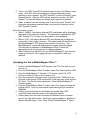
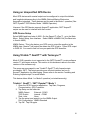
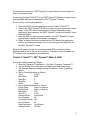
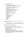
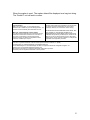
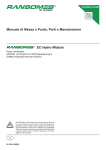
INTRODUCTION TO GPS
WITH 3M™ DYNATEL™
M-SERIES LOCATORS
Track & Trace Solutions
November 2007
78-8135-3403-5 Rev C
Table of Contents
What is GPS? ......................................................................................................3
How does GPS Work? ........................................................................................3
Mapping with GPS ..............................................................................................3
GPS Technology ............................................................................................................. 3
Mapping of 3M™ Electronic Markers ........................................................................... 3
Activating GPS Modes........................................................................................4
Getting the Activation Code ........................................................................................... 4
Inputting the Activation Code......................................................................................... 4
3M™ Dynatel™ GPS Modes ...............................................................................4
Mode 1 Operation – NMEA mode.................................................................................. 5
Mode 2 Operation – GIS mode....................................................................................... 5
Interface to ESRI™ ArcPad™:....................................................................................... 7
Interface to Thales™ MobileMapper™ PRO:................................................................ 7
Mode 3 Operation – PDA – mode .................................................................................. 7
3M™ Dynatel™ Locator Setup...................................................................................... 8
GPS/3M™ Dynatel™ Locator Hookup.......................................................................... 8
GPS/3M™ Dynatel™ Locator Operation....................................................................... 9
Installing and running 3M™ ArcPad™ application scripts ...........................11
Using Trimble™ GeoXT™ and Thales™ MobileMapper™ CE.NET ........................ 11
Installation of 3M™ ArcPad™ application scripts....................................................... 11
Running 3M™ ArcPad™ application scripts ............................................................... 12
Using Thales™ MobileMapper™ PRO.............................................................17
Thales™ MobileMapper™ PRO Setup ........................................................................ 17
Thales™ MobileMapper™ / Dynatel™ Hookup ......................................................... 18
Thales™ MobileMapper™ / 3M™ Dynatel™ Locator Operation .............................. 18
Uploading the Job to MobileMapper Office™ ............................................................. 19
Using an Unspecified GPS Device ..................................................................20
GPS Device Setup......................................................................................................... 20
Using Trimble™ GeoXT™ with Terrasync™ ..................................................20
Trimble™ GeoXT™ / 3M™ Dynatel™ Mode 1 ......................................................... 20
Trimble™ GeoXT™ / 3M™ Dynatel™ Mode 2 (GIS) ............................................... 21
2
What is GPS?
The Global Positioning System (GPS) is a worldwide radio-navigation system
formed from a constellation of 24 satellites and their ground stations. A GPS
receiver uses these satellites as reference points to calculate positions
accurately.
How does GPS Work?
The basis of GPS is "triangulation" from satellites. To "triangulate," a GPS
receiver measures distance using the travel time of radio signals. To measure
travel time, GPS needs very accurate timing. Along with distance, you need to
know exactly where the satellites are in space. High orbits and careful monitoring
are the key. Finally you must correct for any delays the signal experiences as it
travels through the atmosphere.
Mapping with GPS
Historically, utility company maps have been mostly schematic in nature. Hand
drawn maps were often based on sketches completed by engineers or
installation crews. They portrayed the components of the system but their
positioning was not accurate enough. The on-map relationships of key
components such as valves, transformers, and regulators were approximate.
Global positioning system (GPS) technology allows utility companies to increase
the accuracy of their electronic maps to provide more effective facility
management, planning and design.
GPS Technology
Some GPS devices fall into the general class of GPS receivers referred to as
"sub-meter" or "mapping grade." They are capable of a final resolution of
positions within a meter (approx. 40 inches) of their true locations. Note that the
total error will be twice that number between two measurement times.
Furthermore, the worst-case accuracy depends on many factors such as:
number of satellites in view, the position of the satellites, atmospheric conditions,
foliage, buildings etc.
Mapping of 3M™ Electronic Markers
3M™ Dynatel™ M-series Marker Locators can be configured to send iD marker
data directly to some GPS devices. When a marker is located and read, feature
and attribute data is sent to the GPS device and is stamped with latitude,
longitude and date/time data. The data acquired during this logging process can
be uploaded to mapping software, and your markers with all the data read from
them, are on the map!
3
Activating GPS Modes
Getting the Activation Code
The GPS interface feature is available for no cost. The software upgrade and
activation key can be obtained from the website http://www.3m.com/dynatel.
Upgrade the software in your unit using PC Tools, then input the activation code.
Inputting the Activation Code
1. Press the Menu key, then Setup, then >>More until COM softkey is visible.
2. Press the COM key and then select GIS mode. You will be prompted to
input the activation key that you have obtained from the website. This will
have to be performed only one time to enable the GPS interface.
3M™ Dynatel™ GPS Modes
The Locator can interface with wide variety of GPS receivers for example:
Thales™ MobileMapper™, Trimble™ GeoXT™, Garmin™ eTrex™ etc.
Figure 1. 3M™ Dynatel™ Locator with GPS
The Locator sends out the record with the information from the iD marker or
Trace template (from Cable Locate/Path mode) to GPS unit so that it can save
the Data in GIS format.
4
The Locator supports three modes – NMEA, GIS, PDA. The mode can be set
from within the Locator menu. Please refer to the section named “Dynatel setup”.
Mode 1 Operation – NMEA mode
Most GPS devices with a serial output can be configured to output the latitude
and longitude data according to the NMEA (National Marine Electronics
Association) standard. When an iD marker is read, the GPS data is stored with
the marker's data in the Read or Program History memory on the 3M™
Dynatel™ Locator. All of this data can be uploaded into the 3M™ Dynatel™ PC
Locator Tools and can be stored in your database.
Mode 2 Operation – GIS mode
In the GIS mode, the Locator sends out the iD marker record template data to the
external device through the serial port, there by allowing different GIS mapping
capabilities.
Figure 2. 3M™ Dynatel™ Locator in GIS mode
The data that is sent out from the Locator can be used to interface to a custom
application on a smart GPS/GIS device to attach the data to the GPS Log point.
This information is in standard GIS shape file format.
5
Logging is supported from different modes within the Locator. Data is logged
when an iD marker is read or programmed and when exiting the Cable / Sonde
depth mode. If a non-RFID marker is attempted to be read, the data is also
processed and saved by the GPS device.
In GIS mode, whether you use the 3M™ ArcPad™ scripts, or Thales™
MobileMapper™ Pro, the data records sent from the Locator are used to create
different layers on the map based on the record type “description.”
This unique feature of the interface with the 3M™ Dynatel™ M-series Locator
enables the GPS devices to log iD marker record or Trace path records with the
feature points and to group according to the description into different layers.
For example - Five iD markers have exactly the same information
programmed into them. All five contain the information, “Descrptn:
Abandoned”.
• The GPS device will identify all five with a feature name: ‘Abandoned’. As
a result, all of these markers will be grouped together as one layer.
• If the information contained in the marker does not include the label
‘Descrptn’, or if the information varies from marker to marker, the GPS
device will identify each iD marker as “Marker” and uses a subscript
number (sequentially incremented) for each map feature, thereafter.
• Passive markers will also have a feature name of "Marker", but will be
noted in the GPS device as “Not an iD marker”.
• For the Trace path, or cable locate mode, if the label “Descrptn” is not
included, it will be identified as “Trace”.
When the map, or the shape files are exported, all the layers in the Job and the
feature point data records are used by the GIS system.
In the GPS map, all markers will be grouped into separate layers. Each layer
may be turned on or off for viewing, which makes it easier to see separate
groups.
Note: If markers are not programmed with user data in the same order or have
different number of lines of user data, subgroups of feature names may occur.
For example - One marker has 2 user data lines and another has 3. Both
markers have the same "Descrptn": "Conduit",
• The feature name "Conduit" would be assigned for the first iD marker. The
second marker would have the feature name "Conduit1", indicating that
different information is available on each marker, even though both indicate a
‘conduit’ location.
• A third marker with a "Descrptn": "Conduit", with user data programmed in
yet, a different order would have the feature name "Conduit2", etc., etc..
6
Therefore, if this feature is to be of the greatest value, care should be taken in
the development of user data templates (Templates can be created and edited
using the 3M™ Dynatel™ PC Tools software application), and distributed to iD
marker programmers.
Interface to ESRI™ ArcPad™:
Many GPS devices support the Arcpad™ application for mapping. 3M™ has
developed application scripts that runs in Arcpad™ providing a seamless
interface with the 3M™ Dynatel™ M-series Locators for automatically logging
marker and/or location data in standard GIS shape file format with the push of a
button. Trimble™ GeoXT™ and Thales™ MobileMapper™ CE.NET are some
examples of the GPS devices that support Arcpad application.
Please refer to the section on “Installing and running Arcpad scripts” for more
details.
Interface to Thales™ MobileMapper™ PRO:
3M™ Dynatel™ M-series Locators can interface with the Thales™
MobileMapper™ PRO directly (In addition to the support of 3M™ ArcPad™
scripts on MobileMapper™ CE.Net). The data sent out from the Locator is used
to log the “Point” features in MobileMapper™ Pro. The data is also used to
dynamically grow the feature library (set of attributes for a feature) on the
MobileMapper™ Pro, reducing the manual steps needed for mapping.
For each Log point, data is sent to the GPS device and is stamped with latitude,
longitude, elevation and date/time data. The data acquired during this logging
process can then be uploaded to mapping software.
Please refer to the section on “Thales™ MobileMapper™ Setup” for more details.
Mode 3 Operation – PDA – mode
PDA mode is similar to the GIS mode except for one difference. When the
Locator is in the PDA mode, it does not validate the GPS co-ordinates. In the GIS
and NMEA mode, the GPS co-ordinates that the Locator receives are validated
for data integrity. In the PDA mode, the Locator sends the data to the external
device and it is the responsibility of the receiving application to store the data.
The communication protocol is same as for the GIS mode. Please refer to the
section “Data format” for a sample record and explanation of the record.
7
3M™ Dynatel™ Locator Setup
1. Press the Menu key, then Setup, then >>More until COM softkey is visible.
2. Press the COM key. A new screen appears. See figure below.
3. Select the GPS mode based on your requirements and the GPS device
used. GIS mode (mode 2) is preferred as it is more integrated with the
GPS device. In this mode, Arcpad scripts can be run on the GPS device
for logging applications.
4. When GIS or PDA mode is selected, the user can select option to “Log
Prompt” Yes / No. If “Log prompt – No” is selected, the data is sent
automatically when exiting the Cable / Sonde depth mode / iD marker read
/ iD marker program mode. If “Log Prompt - Yes” is selected, the user is
prompted before Logging and is given a chance to Log or skip that point.
Figure 3. COM Setup options in 3M™ Dynatel™ Locator
Note: Remember to change this setting back to "PC" before connecting
the 3M™ Dynatel™ Locator to your PC to use PC Locator tools.
GPS/3M™ Dynatel™ Locator Hookup
1. A Bluetooth adapter can be connected to the Locator to communicate with
GPS units that support “serial port profile” over Bluetooth wireless. Please
refer to the section “Arcpad scripts with Trimble™ GeoXT™” in “Installing
and running Arcpad scripts”.
2. Secure the “null” modem adapter to the 3M™ Dynatel™ Locator serial
port connector (Thales™ MobileMapper™ Pro provides a cable and a
bracket to hold on to the Locator).
3. Connect the GPS device to the null modem adapter using the cable
supplied with the GPS device. If the GPS device is not supplied with a
cable, but has a standard DB9 connector, use the cable provided with
your 3M™ Dynatel™ Locator.
Note: Remember to remove the null modem adapter before connecting to
the 3M™ Dynatel™ Locator to your PC to use PC Locator tools.
8
GPS/3M™ Dynatel™ Locator Operation
Logging is supported in three operating modes of the Locator – iD marker read,
iD marker program, Trace / path / cable locate modes.
1. Turn on 3M™ Dynatel™ M-series Locator. Press Locate/OK and select
the marker locate mode. If the GPS unit is disconnected or has not
acquired enough satellites to give a position, the 3M™ Dynatel™ Locator
will display "Insert External Device". After the GPS unit has acquired a
position, the 3M™ Dynatel™ Locator will display the latitude and longitude
coordinates.
2. When an iD marker is read, the marker data and GPS coordinates will be
displayed on the screen of the 3M™ Dynatel™ Locator and saved to the
Locator's Read Marker History. The data log screen pops up when
Locate/OK button is pressed. Press OK to Log or Exit without logging the
point. From the marker program mode also, the data log screen appears
after the program is complete.
Figure 4. RFID marker interface in GIS mode
3. When marking the trace path, from the cable locate mode, press “Depth”
to measure depth and current. From this screen, exiting the depth mode
will lead to the Log template screen. You can choose to Log the point by
pressing the OK/Locate button or Exit without logging. Please note that
this screen will appear only if you have selected Prompt – Yes. If prompt is
not selected, the data is automatically logged. The Sequence number
(Seq#) can be modified in the log screen and the last used number is
saved. The descriptions (terms in the right hand side of the colon) can be
modified and the modified data is sent to the external device. If you want
to save the changes to these descriptions, you will need to modify them in
the Trace template in the template edit screen (Menu | Data/template |
User template, select “Trace” template)
9
Figure 5. Trace/path marking in GIS mode
The data is transmitted at 4800 baud, 8 bits, 1 – stop bit, no – parity, flow control
- none.
10
Installing and running 3M™ ArcPad™ application scripts
Using Trimble™ GeoXT™ and Thales™ MobileMapper™ CE.NET
ArcPad™ is a stand-alone application that runs on the GPS device. Many GPS
devices including Trimble™ GeoXT™, Thales™ MobileMapper™ CE.NET
support ArcPad™.
3M™ provides the application scripts that would need to be installed on the GPS
device. These scripts provide interface to the 3M™ Dynatel™ Locator and the
ArcPad™ application / GPS device. The scripts are designed to provide Job
management functions and provide mapping functionality.
As the data records come in from the Locator, the record is matched against
previous records. If there is a matching record from an existing “Layer”, the
feature point is added to that layer with all the other GPS data. If the record
belongs to a new type of “description”, a new layer is automatically created and
the feature point is attached.
Please refer to the section “Mode 2 operation – GIS mode” for more details.
Installation of 3M™ ArcPad™ application scripts
It is expected that ArcPad™ application is already installed on the GPS device.
The 3M™ ArcPad™ application scripts run on GPS devices that support
Arcpad™ scripting. The scripts were tested on Trimble™ GeoXT™ and Thales™
MobileMapper™ CE.NET.
The installation of 3M™ Arcpad™ scripts would involve copying the following
NINE files into the “Applets” folder of the Arcpad™ installation where Arcpad.exe
exists on the GPS device.
1. 3MLocator.bmp
3. IDShapefile.vbs
5. language.xml
7. Locator.vbs
9. SambaMan.ico
2. IDShapefile.apl
4. jobs.dbf
6. Locator.apa
8. Sambaman.BMP
These script files are provided in a zip file and can be downloaded from the 3M™
website at www.3M.com/dynatel
The zip file needs to be extracted to a local folder.
Typically, Microsoft ActiveSync application can be used to explore the device.
11
Once ActiveSync recognizes the device, Click on “Explore” button to open
Explorer. For details on how to download and install MS ActiveSync, please visit,
http://www.microsoft.com/windowsmobile/activesync/default.mspx
The Applets folder in the Arcpad™ has to be identified first. This directory is
typically in “Program Files/Arcpad” path. However, if the default directory is not
used, for example, SD card etc, the path could be different.
The Applets folder is where the Arcpad.exe exists. The script files provided by
3M™ needs to go into this Applets folder.
Select all the NINE extracted files from the PC local folder and copy | paste them
onto the GPS device Arcpad/Applets folder.
3M™ will release an install shield program to automatically deploy the scripts to
the target GPS device. It will be posted in the 3M™ website www.3M.com when
available.
Running 3M™ ArcPad™ application scripts
The following is a simplified diagram of how Arcpad™ scripts interact with the
3M™ Dynatel™ Locator. The procedure is similar for all the GPS devices that
support Arcpad™ such as Trimble™ GeoXT™, Thales™ MobileMapper™
CE.NET or on a stand alone PDA that connects to a GPS Bluetooth™ module.
3M™
Dynatel™
Locator
GPS Device
COM6
AUX
COM1
GPS preferences
Arcpad™
Application
Running on
GPS device
GPS device
internal
module
Figure 6. 3M™ application scripts interaction with ArcPad™
3M™ Dynatel™ Locator can communicate with a GPS device using a serial port.
This can be provided with a serial cable or via Bluetooth™ serial port adapter. It
depends on the GPS device and the accessories used. Please check the GPS
device manufacturer’s manual for more information on this.
12
The COM port to communicate with the Locator is configured in the “AUX” setting
in the Arcpad™ Tools menu.
Arcpad™ also needs to communicate with the GPS module / connector internally
in the GPS device. Arcpad™ application has a setting in the ”GPS Preferences”
for selecting the COM port and the associated properties for this setting. Please
refer to the GPS device manufacturer’s manual for more information.
First step: Ensure that the COM ports are configured properly in ArcPad™ in the
GPS device. On the Trimble™ GeoXT™, Bluetooth™ on COM7 can be used to
communicate with the Locator using the serial port profile. COM1 or COM2 can
be used to communicate with the GPS module.
If you are using a stand-alone PDA running Arcpad™ software, your
configuration may be different. Typically, you can use COM7 to communicate
with the external GPS module on Bluetooth™ serial port profile and use COM1 to
communicate with the Locator on a regular serial port cable.
The following illustrations assume that you are using COM7 to communicate with
the Locator and COM1 to communicate with the internal GPS module.
Also, the pictures given here are for illustration only and may vary on your device
depending on the GPS device and the versions of the device that you are using.
1. Start ArcPad™ application. Click on the GPS icon drop arrow.
2. Select GPS Preferences
3. Select COM port for the GPS module and click OK.
Figure 7. Selecting GPS COM port in ArcPad™ Application
13
Next, configure the Auxiliary port.
1.
2.
3.
4.
Click on the Tool Box Icon drop arrow.
Select Options.
Click Right arrow until AUX tab appears in the bottom of the screen.
Click AUX. Set port COM port as shown.
Figure 8. Selecting GPS COM port in ArcPad™ Application
You will need to configure the Bluetooth™ adapters if you are using Bluetooth™
serial port communication in your environment. Several third party Bluetooth™
serial port adapters that support serial port profile are available in the market.
One example of such a Bluetooth™ adapter that we have tested is SENA PromiSD 101/202 with internal rechargeable battery. Currently, the 3M™ Dynatel™
Locator does not supply the power to the external Bluetooth™ adapter.
Establish Bluetooth communication to GPS unit.
1. Select the connection icon
2. Bluetooth Manager
3. Select a Bluetooth icon (double
click) either one, at this point.
4. Icon will show double green
arrows when connected.
Figure 9. Configuring Bluetooth Serial port on the GPS device
14
Again, the very important part in making the GPS device to communicate with the
Locator is to configure the serial ports correctly. Once all the connections are
established, you can verify the connectivity as follows.
Start the Job by clicking on the Locator-man Icon in Arcpad™ application
Locator-man Icon
on the Toolbar
Figure 10. Starting 3M™ Application scripts in ArcPad™
3M Application scripts for ArcPad provide Job management capabilities. When
you start the scripts, you are prompted to Select an existing Job or create a new
Job. To create a new Job, type a name for the new Job and click “OK”. You will
be prompted to select a Map for the Job.
Figure 11. Selecting existing / create new Job
15
Configure the Locator. Please refer to the section “3M™ Dynatel™ Locator
Setup” for more details.
Go to the Marker Locate mode in the Locator.
Latitude and Longitude Coordinates should now appear on the Receiver Screen
in Marker Locate or Cable Locate/Trace path mode in the Log template screen
after the Depth screen.
Now, if you read an iD marker you should see the marker record passed on to
the GPS device and logged.
You can also verify it from the Cable locate / Trace path depth mode as
described in the “Mode 2 operation – GIS mode”
As the data records from the 3M™ Dynatel™ Locator™ are logged by the
scripts, these are identified with distinct marks by layers. You can select the
marks, and look at the data record.
Figure 12. Data Feature Point attribute pages (Ex. Trace path mode record)
16
Using Thales™ MobileMapper™ PRO
The Thales™ MobileMapper™ can be used in Mode 1 (NMEA) and Mode 2
(GIS) operations simultaneously. Your 3M™ Dynatel™ M-series Locator may
need a hardware upgrade to be used with the Thales™ MobileMapper™ in
Mode 2 (GIS) operation (See 3M™ Dynatel™ Locator setup below).
Thales™ MobileMapper™ PRO Setup
For mode 2 operation, it is recommended that a new feature library entry be
created in MobileMapper OfficeTM and downloaded to the MobileMapper™
device as follows:
1. From the MobileMapper™ Office™ toolbar, select Tools, Feature Library
Editor.
2. From the Feature Library Editor window toolbar, select File, New. The #
of feature types: should be 0.
3. Select File, SaveAs and save the file as "Dynatel.mmf". Close the editor
window.
4. Connect the MobileMapper™ GPS device to the PC's Com port and turn
the unit on.
5. From the MobileMapper Office™ toolbar, select File, Download from GPS.
6. From the MobileMapper™ Transfer -> PC window, select File, GPS
Device via Cable (or click on the Connect icon).
7. Once the connection has been made, drag the new file, Dynatel.mmf, from
the right pane of the window (PC side) to the left pane of the window (GPS
device side). The new feature library entry is downloaded.
On the MobileMapper™ GPS device:
1. Press the "Menu" key and scroll to Setup and Enter.
2. Scroll to NMEA and Enter, then select V2.1GSA and Enter.
3. Scroll to Baud Rate and Enter, then select 4800 Baud and Enter.
Note: Connecting the GPS device to MobileMapper Office™ will
automatically reset the NMEA mode and the Baud rate, so this setup will
have to be repeated after each download/upload.
17
Please refer to the section “3M™ Dynatel™ Locator setup” for details on setting
up the Locator.
Thales™ MobileMapper™ / Dynatel™ Hookup
1. Secure the “null” modem adapter to the 3M™ Dynatel™ Locator serial
port connector.
2. Connect the MobileMapper™ to the null modem adapter using the cable
supplied with the MobileMapper™.
The users are encouraged to use third party accessories including null modem,
custom cable and mounting bracket are available (example: Igage Mapping
Corpn, Salt Lake city, UT 84105)
Figure 13. Thales™ MobileMapper™ mounted on 3M™ Dynatel™ Locator
Note: Remember to remove the null modem adapter before connecting the
3M™ Dynatel™ Locator to your PC to use PC Locator tools.
Thales™ MobileMapper™ / 3M™ Dynatel™ Locator Operation
1. If the MobileMapper™ GPS device has been connected to MobileMapper
Office™ since the last logging operation, setup NMEA to V2.1GSA and
Baud Rate to 4800 Baud.
2. Press LOG or MENU on the MobileMapper™ GPS device.
3. Select Create a New Job. Enter a Job Name and select OK and press
Enter.
4. From the Feature Library window, select DYNATEL.MMF and Enter.
18
5. Turn on the 3M™ Dynatel™ M-series Locator and go to the Marker locate
mode. If the GPS unit is disconnected or has not acquired enough
satellites to give a position, the 3M™ Dynatel™ Locator will display "Insert
External Device". After the GPS unit has acquired a position, the 3M™
Dynatel™ Locator will display the latitude and longitude coordinates.
6. When a marker has been located, wait 10 seconds for the Thales™ unit
to acquire and average positional data, then press the Read key on the
3M™ Dynatel™ Locator.
When the marker is read:
• Mode 1 (NMEA): the marker data and GPS coordinates will be displayed
and saved to the Locator's memory. This data can be uploaded into 3MTM
3M™ Dynatel™ PC Locator tools and added to your database.
• Mode 2 (GIS): the marker data and GPS coordinates will be displayed
and stored in the Locator’s memory. The marker data will also be sent to
the MobileMapper™ GPS device to be stored in its memory. The
MobileMapper™ screen will display that the marker has been logged.
This data can be uploaded to MobileMapper Office™ where the
appropriate file(s) can be exported to mapping software.
7. When finished, push the Menu key on the MobileMapper™ and close the
mapping for this job. The logging job may be reopened to add new
markers.
Uploading the Job to MobileMapper Office™
1. Connect the MobileMapper™ GPS device to the PC's Com port and turn
the unit on.
2. From the MobileMapper Office™ toolbar, select File, Download from GPS.
3. From the MobileMapper™ Transfer -> PC window, select File, GPS
Device via Cable (or click on the Connect icon).
4. Once the connection has been made, drag the job file (*.MMJ) from the
left pane of the window (GPS device side) to the right pane of the window
(PC side). The file should be transferred. Close the MobileMapper™
Transfer window.
5. From the MobileMapper Office™ toolbar, select File, Open and open the
logging job file. Icons for each marker located during the job should be
displayed.
6. Clicking on the individual icon will display the marker data, GPS
coordinates and other information in the right side window.
7. Clicking away from the icons will display the different layers of marker
types in the right side window. Each layer may be enabled or disabled to
see the separate layers. See "Using Thales™ MobileMapper™" above.
19
Using an Unspecified GPS Device
Most GPS devices with a serial output can be configured to output the latitude
and longitude data according to the NMEA (National Marine Electronics
Association) standard. These devices can be used in the Mode 1 operation (See
3M™ Dynatel™ GPS Modes, Mode 1 NMEA Operation).
However if the GPS device supports Arcpad™ application, 3M™ Arcpad™
scripts can be used to interface with the Locator.
GPS Device Setup
Select NMEA and baud rate of 4800. On the Garmin™ eTrex™, go to the Main
Menu. Select Setup, then Interface. Select NMEA In/NMEA Out (the Baud rate
is fixed to 4800).
NMEA Datum - This is the datum your GPS uses to output the position in the
NMEA data. Garmin™ will output the datum the GPS is set to. Other GPS output
in WGS 84. You need to find out how your particular GPS does this.
Using Trimble™ GeoXT™ with Terrasync™
Mode 2 (GIS) operation is not supported in the 3M™ Dynatel™ Locator software
version 17 and newer versions. This section in this document refers to the older
versions of the software only.
The users are encouraged to use Trimble™ GeoXT™ with Arcpad scripts
provided by 3M™. The scripts provide more efficient interface and run in
Arcpad™ application for data logging. Please refer to the section “Installing and
Running Arcpad scripts” for more details.
This device allows Mode 1 or Mode 2 operation (not simultaneously).
Trimble™ GeoXT™ / 3M™ Dynatel™ Mode 1
1. Open the GPS Connector application. Tap Start, Programs,
Communication, GPS Connector.
2. Tap Setup on the folder tab.
NMEA Output:
External - COM1
TSIP Output:
Internal - COM3
Real - time:
None
3. Tap the setup icon (wrench) on the NMEA Output.
Port Configuration: NMEA Standard
4. Tap OK. Tap OK again.
20
Please refer to the section “3M™ Dynatel™ Locator Setup” for more details on
how to setup the Locator.
Connect the Trimble™ GeoXT™ to the 3M™ Dynatel™ M-series Locator using a
standard DB9 cable as provided with the 3M™ Dynatel™ Locator.
Do not use the “null” modem adapter!
1. Open the GPS Connector application on the Trimble™ GeoXT™.
2. Turn on the 3M™ Dynatel™ M-series Locator and go to the marker locate
mode. If the GPS unit is disconnected or has not acquired enough
satellites to give a position, the 3M™ Dynatel™ Locator will display "Insert
External Device".
3. After the GPS unit has acquired a position, the 3M™ Dynatel™ Locator
will display the latitude and longitude coordinates.
4. When a marker has been located and the GPS device has acquired a
position with adequate precision for your needs, press the Read key on
the 3M™ Dynatel™ Locator.
When an iD marker is read, the marker data and GPS coordinates will be
displayed and saved to the Locator's memory. This data can be uploaded into
PC Locator tools and added to your database.
Trimble™ GeoXT™ / 3M™ Dynatel™ Mode 2 (GIS)
Set up the external sensor as follows:
1. Open the Terrasync™ application. Tap Start, Programs, Terrasync™.
2. Tap the Section List in the upper left hand corner and select Setup.
3. Tap External Sensors settings then tap Properties. Enter "Dynatel MSeries".
4. Set up Communications as follows:
Port:
COM 1
Baud Rate:
4800
Data Bits:
8
Stop Bits:
1
Parity:
None
5. Set up Data Identification as follows:
Prefix String
blank, no spaces.
Suffix String
blank, no spaces.
Max Bytes
100
Time Out
0.10s
Receive Mode
Unsolicited
Point Feature
All
Line/Area Feature Off
Not in Feature:
All
Data Destination
As Attribute
Attribute Name:
iD Data
21
6. Tap OK. Tap OK again.
Create iD Marker Dictionary as follows:
1. Tap the SECTION LIST and SELECT DATA
2. Tap the SUB SECTION BOX and SELECT FILE MANAGER
3. Choose File Type:
Dictionaries
4. Tap the Option button and choose New dictionary.
5. Create dictionary file: "Dynatel"
6. Tap OK
7. Tap the Option button and choose Edit dictionary.
8. Tap the Edit and select New Feature
9. Enter the Feature Name:
"ID Marker"
10. Select Feature Classification as Point
11. Tap OK.
12. Tap the Edit and select New Attribute
13. Select New Attribute type as Text
14. Tap Add
15. Enter Attribute Name: " iD Data "
16. Enter Length: "100"
17. On Creation: Normal
18. On Update: Normal
19. No increment
20. Tap OK
21. CLOSE
22. Tap Save
23. tap OK.
Please refer to the section “3M™ Dynatel™ Locator Setup” for more details on
how to setup the Locator.
•
Connect the Trimble™ GeoXT™ to the 3M™ Dynatel™ M-series Locator
using a standard DB9 cable as provided with the 3M™ Dynatel™ Locator.
Note: Do not use the null modem adapter!
Start a new logging job on the Trimble™ as follows:
1. Tap the Section List in the upper left hand corner and tap Data.
2. Tap the Sub-Section BOX in the upper left hand corner and tap New File.
3. Enter the logging file name.
4. File Type:
Rover
5. Select Dictionary Name: ID Marker
6. Tap Create and confirm Antenna Height.
7. Turn on the 3M™ Dynatel™ Locator and go to the marker locate mode.
8. When a marker has been located and the GPS device has acquired a
position with adequate precision for your needs, press the Read key on
the 3M™ Dynatel™ Locator.
22
When the marker is read: The marker data will be displayed as a long text string.
The Trimble™ unit will ask to confirm.
Important Notice
Before using this product, you must evaluate it and
determine if it is suitable for your intended application. You
assume all risks and liability associated with such use.
Warranty; Limited Remedy; Limited Liability.
The 3M scripts described herein are warranted to be free
ofdefects in material and manufacture as of the time of
purchase. Thewarranties for all other 3M products
referenced herein are stated in theapplicable Product
Literature, available upon request.
All items made byothers and specified by such brand which
are referenced herein arewarranted only to the extent
specifically stated by the manufacturer ofsuch item(s).
3M MAKES NO OTHER WARRANTIES INCLUDING, BUT
NOT LIMITED TO, ANY IMPLIED WARRANTY OF
MERCHANTABILITY OR FITNESS FOR A PARTICULAR
PURPOSE. Except where prohibited by law, 3M will not be
liable for any loss or damage arising from this 3M product,
whether direct, indirect, special, incidental or consequential
regardless of the legal theory asserted.
ArcPad is a registered trademark of Environmental Systems Research Institute, Inc. (ESRI)
Trimble GeoXT is a registered trademark of Trimble Navigation Ltd.
Thales MobileMapper Pro and MobileMapper CE.NET are registered trademarks of Magellan Navigation, Inc.
Garmin eTrex is a registered trademarks of Garmin Ltd.
Microsoft and ActiveSync are registered trademarks of Microsoft Corporation.
3M and Dynatel are registered trademarks of 3M Corporation.
23