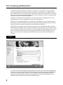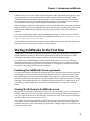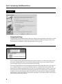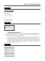
1
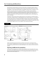
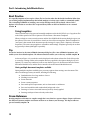
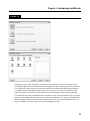
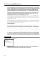
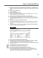
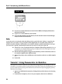
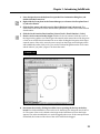
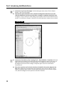
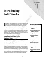
CHAPTER
TE
RI
AL
Introducing
SolidWorks
I
MA
n SolidWorks, you build 3D parts from a series of simple 2D sketches and
features such as extrude, revolve, fillets, cuts, and holes, among others.
You can then create 2D drawings from the 3D parts and assemblies.
TE
D
This chapter will familiarize you with some of the tools available to make
the transition to SolidWorks, and with some of the basic facts and concepts
that you need to know to get the most out of the software.
GH
If you want to start using the software without learning about how or why it
works, you can skip directly to Chapter 3 for sketches or Chapter 4 to start
making simple parts, assemblies, and drawings. Of course, I recommend you
get a bit of background and some foundation first.
IN THIS CHAPTER
Installing SolidWorks
Getting started with
SolidWorks
Identifying different types of
SolidWorks documents
Getting familiar with featurebased modeling
RI
Looking at history-based
modeling
Installing SolidWorks for
the First Time
PY
Creating changeable sketches
CO
Some of you will have SolidWorks installed for you by people in your company or by SolidWorks reseller experts, and some of you will do the installation on your own. Regardless, it is best to make sure that your hardware and
software are compatible with the SolidWorks system requirements, available on the SolidWorks Web site at www.solidworks.com/sw/support/
SystemRequirements.html.
SolidWorks installs natively on both 32- and 64-bit operating systems. It is
only supported for Windows XP, Vista, and Windows 7. In all cases, the professional-level OS is recommended. Although, it is possible to install and run
SolidWorks under Parallels and Boot Camp on Apple hardware, that configuration is not supported or tested by SolidWorks Corporation or its resellers.
You can find video card requirements at the above link for system requirements. The main concern with a video card for SolidWorks is that it be
3
Controlling changes with
Design Intent
Modifying Design Intent
Working with links between
documents
Creating a template part
tutorial
Using parametrics in sketches
tutorial
Part I: Introducing SolidWorks Basics
compatible with OpenGL. Hardware changes too rapidly for me to give specific recommendations
here, but generally, nVidia brand boards in the Quadro line are acceptable, as are AMD/ATI brand
boards in the FirePro line. You should expect to pay $100 to $500 for a serviceable low- to mid-range
video card. Cards that are marketed as game cards, such as the Radeon or GeForce, have known limitations and do not work well with SolidWorks.
In addition to installing the correct hardware, you also need to have a compatible driver version
installed. Again, refer to the SolidWorks system requirements Web site.
Whether you are installing SolidWorks or someone else is installing it for you, you should consider
purchasing a copy of the SolidWorks Administration Bible (Wiley, 2010), which contains all the information you need on installing, configuring, and troubleshooting SolidWorks.
Alternatively, you might not want to get that involved at first. You can install the software with all
defaults just to get started, using it as a practice installation, especially if you intend to learn as much
as you can about it, and then come back and do a more thorough job of implementing it later. If this is
the case, just put the DVD in the drive and accept all the defaults. In the Summary page, shown in
Figure 1.1, you can choose to change the disk installation location and choose which products are
installed.
FIGURE 1.1
Changing installation settings on the Summary install page
You should count on the installation requiring about 6GB of space on your hard drive, depending on
the options you select to install. The locations of files on your computer will vary by SolidWorks version, by your operating system, and by your own installation choices, but the bulk of the files are
placed into two separate folders: the Program Files folder (C:\Program Files\SolidWorks Corp\
SolidWorks) and the Toolbox Data folder (C:\SolidWorks Data).
4
Chapter 1: Introducing SolidWorks
SolidWorks 2011 also creates a folder in the My Documents folder called GaBi which appears to only
have empty folders, but you should not remove it. Also in My Documents are two folders called
SolidWorks Downloads and SolidWorks Visual Studio Tools for Applications. Both of these should
also remain where they are. The SolidWorks Downloads folder is a good place to look for items that
are downloaded automatically from the Background Downloader or the SWIM.
When installing any software, it is best practice to exit out of all other software first, turn off antivirus
software, make sure you have enough hard drive space and otherwise meet the system requirements
outlined on the SolidWorks System Requirements Web page, and reboot when the installation is
complete.
You can also install without a DVD, using downloaded data instead. To do this, you need a subscription account for the Customer Portal area of the SolidWorks Web site at www.solidworks.com/sw/
support/Subscription Services.html.
Trial installations, network licenses, student versions, administrative images, and other special cases
may require that you contact your reseller for technical support.
Starting SolidWorks for the First Time
SolidWorks has many tools for beginning users that are available when the software is installed. A
default installation presents you with several options when the software is started the first time.
Following is a description of these options, and how you can most benefit from them.
If you plan to go to formal SolidWorks reseller-based training classes, it is a very good idea to go
through some of the tutorials mentioned in this section first; this way you are prepared to ask educated questions and have a leg up on the rest of the class. You will get more out of the training with
the instructor if you have seen the material once before.
Examining the SolidWorks license agreement
It is useful to be familiar with what this document says, but the agreement does not have any bearing
on learning how to use the software other than the fact that it allows for a Home Use License. Many
users find this part of the license agreement helpful. The primary user of the license at work is also
allowed to use the license at home or on a portable computer. This is often a good option for learning
techniques, doing additional practice, or completing the design of that deck or soapbox derby car. If
your employer uses floating licenses, the rules are somewhat different. Contact your reseller for
details.
Viewing the Welcome to SolidWorks screen
The Welcome to SolidWorks screen, shown in Figure 1.2, is the next thing to greet you. This helps you
establish what type of tools you would like to see in the interface and gives you some help options.
You may not get the chance to see this dialog box if someone else, such as an IT person, has installed
and done an initial test on your software for you.
If you make a choice that you would like to change later, the options presented in this dialog box are
also available elsewhere. Although you will not see this dialog box again, the interface is highly customizable and options exist for most things you might want to change. Chapter 2 covers interface customization in more detail.
5
Part I: Introducing SolidWorks Basics
FIGURE 1.2
The Welcome to SolidWorks screen
Using Quick Tips
The Quick Tips setting enables balloons with tips to help you get started with several tasks. For example, the first Quick Tip you see may be the one shown in Figure 1.3. When you begin to create your
first document in SolidWorks, a Quick Tip helps guide you on your way.
FIGURE 1.3
The SolidWorks Document Quick Tip
As you continue working, Quick Tips displays a box, shown in Figure 1.4, at the lower-right corner of
the Graphics Window that offers context-sensitive help messages. As you work with the software,
these messages change to remain relevant to what you are doing.
You can turn Quick Tips on or off by clicking the small square on the Status Bar in the lower-right corner, as shown in Figure 1.5. You can turn the Status Bar on or off in the View menu; however, the
Status Bar serves many useful purposes for all users, so I recommend you leave it active. You can also
turn Quick Tips off in the Help menu by deselecting Quick Tips. The on/off setting is document-type
sensitive, so if you deselected Quick Tips off in part mode, you will need to do it again for assemblies
and drawings, as well. Quick Tips are a great way to get going or to get a little refresher if it has been a
while since you last saw the software.
6
Chapter 1: Introducing SolidWorks
FIGURE 1.4
The main Quick Tip window
FIGURE 1.5
Turning Quick Tips on or off
Creating a new document
To start a new SolidWorks document, click the New icon in the title bar of the SolidWorks application.
With standard functions such as creating a new document, SolidWorks works just like a Microsoft
Office application, and the icons even look the same.
The first time you create a document, SolidWorks prompts you to select units for your default templates, as shown in Figure 1.6. This is an important step, although you can make changes later if
needed. SolidWorks stores most of the document-specific settings in document templates, which you
can set up with different settings for each type of document — parts, assemblies, and drawings. More
information on part and assembly templates can be found later in this chapter. Drawing Templates
are described in detail in Chapter 14.
FIGURE 1.6
The default template units selection
7
Part I: Introducing SolidWorks Basics
One of the most common questions new users ask is how they can change the default so that new
documents come up with a certain type of units every time. Units in new documents are set within
the templates. To create a part with inch units, use a template with inch units. You can have as many
templates as you want, and can have a different template for each type of units you might use.
ISO (International Organization for Standardization) and ANSI (American National Standards
Institute) standards use different methods of projecting views, and these standards are controlled by
templates. ISO is typically a European standard and uses First Angle Projection, while ANSI is an
American standard and uses Third Angle Projection. The standard projection used throughout this
book is Third Angle.
The difference between Third and First angle projections can cause parts to be manufactured incorrectly if those reading the prints (or making the prints) do not catch the difference or see that there is
some discrepancy. Figure 1.7 demonstrates the difference between the two projection types. Make
sure to get the option correct. If someone else, such as a computer specialist who is not familiar with
mechanical drafting standards, initially sets up SolidWorks on your computer, you will want to verify
that the default templates use the correct standards, units, and projection method.
FIGURE 1.7
Differences between First (left) and Third (right) angle projections
First angle projection
Third angle projection
Another setting affecting projections that you will want to check can be accessed by choosing
Tools ➪ Options ➪ Display/Selection ➪ Projection type for four-view viewport. This does not follow
the dimensioning standard selected for the default templates or the country in which the software is
installed.
Exploring SolidWorks documentation
Several types of documentation are available to help SolidWorks learners along their path. A great
place to start is the SolidWorks Resources tab in the Task Pane (on the right side of the screen). This
is the first tab in the list and has the Home icon. The Getting Started option in the SolidWorks
Resources tab is shown in Figure 1.8.
8
Chapter 1: Introducing SolidWorks
FIGURE 1.8
The Getting Started option on the SolidWorks Resources tab of the Task Manager
The terminology SolidWorks has used over the past several releases has changed and may seem
confusing to some of you. In 2007, SolidWorks changed the name Online User’s Guide to SolidWorks
Help. This is a help file on the local computer; it is not online in that it is not on the Internet. In 2010,
the SolidWorks Web Help option was added to the Help menu. This option is online in that it is on the
Internet.
Accessing tutorials
You can access several tutorials by selecting the SolidWorks Tutorials option from the Help menu.
There you will find a list of tutorials on subjects from sheet metal to macros in parts, assemblies, and
drawings. These tutorials are certainly worth your time and will build your skills and knowledge of
basic functionality. This SolidWorks Bible distinguishes itself from the tutorials by going into far more
detail and depth about each function, adding information such as best practices, performance considerations, and cautionary data, acting as a thorough desk reference. The purpose of this book is not to
duplicate all the resources for beginners, but to take the information into far more depth and detail
and answer the “why” questions instead of just the “how” questions.
Keeping up with what’s new
With every release, SolidWorks publishes a What’s New document to help you keep up to speed with
the changes. This is typically a PDF file with accompanying example files. If you have missed a version
or two, reading through the What’s New files can help get you back on track. (You can find every
What’s New document on Ricky Jordan’s blog, at http://rickyjordan.com.) Again, don’t expect
many details or interface screen shots; it introduces you to the basic changes.
Moving from 2D to 3D
The Help menu contains a selection called Moving from 2D to 3D. It is intended to help transitioning
users acclimate to their new surroundings. Terminology is a big part of the equation when making
this switch and figures prominently in the Moving from 2D to 3D help file.
Likely, the most helpful sections in Moving from 2D to 3D are Approach to Modeling and Imported
AutoCAD Data. The information in these categories is useful whether you are coming to SolidWorks
from AutoCAD or from another CAD package.
Exploring SolidWorks Help
SolidWorks Help (formerly The Online User’s Guide) is the new Help file. There are two formats: the
traditional Help format and a Web-based help file. You can use Search capabilities to find what you
are looking for. The SolidWorks Help has tutorials and a separate API (application programming
interface) help file. Frankly, it lacks detail and often skips over important facts such as what you
might use a certain function for, what the interface looks like, or where you might find the command
9
Part I: Introducing SolidWorks Basics
in the first place. This SolidWorks Bible fills in the gaps in information about the standard version of
the software.
Checking out the Tip of the Day
The SolidWorks Tip of the Day is displayed at the bottom of the SolidWorks Resources tab in the Task
Pane. Cycling through a few of the tips or using them to quiz coworkers can be a useful skills-building
exercise.
Switching from hardcopy documentation
Unfortunately, hardcopy documentation has dwindled from all software companies. Software suppliers often claim that keeping up with the changes in print is too much work and inefficient. This is the
same reason that SolidWorks gives for changing from help files that are on your local computer to
help files that are only available across the Internet. Still many users prefer to have a physical book in
their hands, one they can spread out on the desk next to them; earmark, highlight, and mark with
Post-its; and take notes in, as evidenced by you holding this book at this moment. Electronic documentation certainly has its advantages, but hardcopy also has its place.
Identifying SolidWorks Documents
SolidWorks has three main data type files: parts, assemblies, and drawings; however, there are additional supporting types that you may want to be familiar with if you are concerned with customization and creating implementation standards. Table 1.1 outlines the document types.
TABLE 1.1
Document Types
Design Documents
Description
.sldasm
SolidWorks assembly file type
.slddrw
SolidWorks drawing file type
.sldprt
SolidWorks part file type
Templates and Formats
Description
.asmdot
Assembly template
.asmprp
Assembly custom properties tab template
.drwdot
Drawing template
.drwprp
Drawing custom properties tab template
journal.doc
Design journal template
.prtdot
Part template
.prtprp
Part custom properties tab template
10
Chapter 1: Introducing SolidWorks
Templates and Formats
Description
.sldbombt
BOM template (table-based)
.sldtbt
General table template
.slddrt
Drawing sheet format
.sldholtbt
Hole table template
.sldrevtbt
Revision table template
.sldwldtbt
Weldment cutlist template
.xls
BOM template (Excel-based)
Library Files
Description
.sldblk
Blocks
.sldlfp
Library part file
Styles
Description
.sldgtolfvt
Geometric tolerance style
.sldsffvt
Surface finish style
.sldweldfvt
Weld style
Symbol Files
Description
gtol.sym
A symbol file that enables you to create custom symbols
swlines.lin
A line style definition file that enables you to create new line styles
Others
Description
.btl
Sheet metal bend table
calloutformat.txt
Hole callout format file
.sldclr
Color palette file
.sldreg
SolidWorks settings file
.sldmat
Material database
.sldstd
Drafting standard
.swb, swp
Macros, macro features
.txt
Custom property file, sheet metal bend line note file
.xls
Sheet metal gauge table
Saving your setup
If you have taken time to set up a computer and then need to reinstall SolidWorks, move to another
computer, or duplicate the setup for another user, you need to copy out the files you have used or
customized. By default, all these files are located in different folders within the SolidWorks installation directory. Chapter 2 deals with interface settings and creating a registry settings file to copy to
other computers or use as a backup.
11
Part I: Introducing SolidWorks Basics
Best Practice
It is especially important to have copies of these files in a location other than the default installation folder when
you are doing complex implementations that include templates of various types of tables or customized symbol
files. Uninstalling SolidWorks or installing a new version will wipe out all your hard work. Choose Tools ➪
Options ➪ File Location to save these files in separate library folders on the local hard drive or on a network
location. n
Using templates
I have included some of my part and assembly templates on this book’s DVD for you. Copy these files
to the folder specified at Tools ➪ Options ➪ File Locations ➪ Document Templates.
When you begin to create a new document, and the New SolidWorks Document dialog box gives you
the option to select one of several files to start from, those files are templates. Think of templates as
“start parts” that contain all the document-specific settings for a part (Tools ➪ Options ➪ Document
Properties). The same concept applies to assemblies and drawings. Templates generally do not have
any geometry in them (although it is possible).
Tip
The Novice interface for the New SolidWorks Document dialog box (File ➪ New SolidWorks Document) only
enables you to select default templates. The Advanced interface enables you to select any available template. n
As shown in Figure 1.9, several tabs can be displayed on the advanced interface. Each of these tabs
is created by creating a folder in the template directory specified in the Options dialog box (Tool ➪
Options). To remove any confusion, I want to note that in Figure 1.9, the Advanced interface shows
the button labeled Novice, and the Novice interface shows the button labeled Advanced.
Having multiple document templates available
Having multiple templates available gives you many options when starting a new document. This
offers an advantage in many situations, including the following:
l
Standardization for a large number of users
l
l
Working in various units
Preset materials
Preset custom properties
Parts with special requirements, such as sheet metal or weldments
Parts and assemblies with standardized background colors
Drawings of various sizes with formats (borders) already applied
l
Drawings with special notes already on the sheet
l
l
l
l
Cross-Reference
Drawing templates and formats are complex enough that I cover them in a separate chapter. Chapter 14 discusses
the differences between templates and formats and how to use them to your advantage. This chapter addresses
part and assembly templates. n
12
Chapter 1: Introducing SolidWorks
FIGURE 1.9
The Novice and Advanced interfaces for the New SolidWorks Document dialog box
Depending on your needs, it might be reasonable to have templates for metric and inch part and
assembly, templates for steel and aluminum, and templates for sheet metal parts and for weldments,
if you design these types of parts. If your firm has different customers with different requirements,
you might consider using separate templates for each customer. Over time, you will discover the
types of templates you need, because you will find yourself making the same changes repeatedly.
You should also note that in SolidWorks 2011 templates can also control document scenes. A system
option controls whether the document scene or a system background color option is the default. The
default setting for this gives the document scene precedence over the system background color settings. See Chapter 5 for more details on scenes and background colors.
13
Part I: Introducing SolidWorks Basics
To create a template, open a document of the appropriate type (part or assembly), and make the settings you want the template to have; for example, units are one of the most common reasons to make
a separate template, though any Document Property setting is fair game for a template, from the
dimensioning standard used to the image quality settings. You can find these settings through the
menus at Tools ➪ Options ➪ Document Properties.
Some document-specific settings do not appear in the Document Properties dialog box. Still, these
settings are saved with the template. Settings that fall into this category are the View menu entity
type visibility option and the Tools ➪ Sketch Settings menu options.
Custom Properties are another piece of the template puzzle. If you use or plan to use BOMs (Bills of
Materials), PDM (Product Data Management), or linked notes on drawings, you need to take advantage of the automation options available with custom properties. Setting up custom properties is covered in detail in Chapter 14.
In addition, the names of the standard planes are template specific. For example, the standard planes
may be named Front, Top, and Side; or XY, XZ, and ZY; or Plane1, Plane2, and Plane3; or North, Plan,
and East; or Elevation, Plan, and Side for different uses.
Locating templates
You can set the location of the templates folder at Tools ➪ Options ➪ File Locations ➪ Document
Templates. The folder location may be a local folder or a shared network folder. Multiple folders may
be specified in the list box, each corresponding to a tab in the New Document’s Advanced interface.
After all the Document Properties, custom properties, and other settings are set to your liking and you
are ready to save the file as a template, choose File ➪ Save As and select Part Templates in Files of Type.
SolidWorks prompts you to save the template in the first folder listed in the File Locations list. You can
create assembly templates the same way, except you change the settings for an assembly document.
You can also create additional tabs on the New SolidWorks Document dialog box by making subfolders in the main folder in the File Locations area. For example, if your File Locations list for Document
Templates looks like Figure 1.10, your New SolidWorks Document dialog box will look like Figure 1.11.
FIGURE 1.10
The Tools ➪ Options ➪ File Locations list
Adding subfolders to either of the locations listed in File Locations results in additional tabs in the
New SolidWorks Document dialog box, as shown in Figures 1.12 and 1.13.
14
Chapter 1: Introducing SolidWorks
FIGURE 1.11
The New SolidWorks Document dialog box
FIGURE 1.12
Additional subfolders added to a File Locations path
FIGURE 1.13
The tabs associated with the subfolders in New SolidWorks Document dialog box
Using default templates
Default templates are established at Tools ➪ Options ➪ Default Templates. The default templates must
be in one of the paths specified in File Locations. Figure 1.14 shows the Default Templates settings.
FIGURE 1.14
The Tools ➪ Options ➪ Default Templates settings
15
Part I: Introducing SolidWorks Basics
There are two Default Template options: Always use these default document templates and Prompt
user to select document template. The Default Template options apply to situations when a template
is required by an automatic feature in the software such as an imported part or a mirrored part. In
this situation, depending on the option selected, the system automatically uses the default template
or the user is prompted to select a template.
Performance
Allowing the software to apply the default template automatically can have a great impact on speed. This is especially true in the case of imported assemblies, which would require you to select templates manually for each
imported part in the assembly if the Prompt user to select document template option is selected. n
Sharing templates
If you are administering an installation of a large number of users, or even if there are just a couple of
users working on similar designs, shared templates are necessary. If every user does what she thinks
best, you may get an interesting combination of conflicting ideas, and the consistency of the company’s documentation may suffer. Standardized templates cannot make users model, assemble, and
detail in exactly the same way, but they do start off users on the same foot.
To share templates among several users, create a folder for templates on a commonly accessible network location, preferably with read-only access for users and read-write permissions for administrators. Then point each user’s File Locations and Default templates to that location. Access problems
due to multiple users accessing the same files do not arise in this situation because users copy templates to create new documents and do not use them directly.
Caution
One of the downfalls of this arrangement is that if the network goes down, users no longer have access to their
templates. This can be averted by also putting copies of the templates on the local computers; however, it has the
tendency to undermine the goal of consistent documentation. Users may tend to use and customize the local templates rather than use the standardized network copies.
CAD administration and organizing any group of people on some level always comes down to trusting employees
to do the right thing. There is no way to completely secure any system against all people trying to work around the
system, so you must rely on hiring people you can train and trust. n
Understanding Feature-Based Modeling
You need to be familiar with some terminology before diving into building models with SolidWorks.
Notice that I talk about “modeling” rather than “drawing,” or even “design.” This is because
SolidWorks is virtual prototyping software. Whether you are building an assembly line for automotive parts or designing decorative perfume bottles, SolidWorks can help you visualize your geometrical production data in the most realistic way possible without actually having it in your hand. This is
more akin to making a physical model in the shop than drawing on paper.
16
Chapter 1: Introducing SolidWorks
“Feature-based” modeling means that you build the model by creating 2D sketches and applying processes (features) to create the 3D shape. For example, you can create a simple box by using the
Extrude process, and you can create a sphere using the Revolve process. However, you can make a
cylinder using either process, by revolving a rectangle or extruding a circle. You start by visualizing
the 3D shape, and then apply a 3D process to a 2D sketch to create that shape. This concept on its own
is half of what you need to know to create models with SolidWorks.
Figure 1.15 shows images of simple feature types along with the 2D sketches from which they
were created.
FIGURE 1.15
Simple extruded and revolved features
Many different feature types in SolidWorks enable you to create everything from the simplest geometry shown in Figure 1.15 to more complex artistic or organic shapes. In general, when I talk about
modeling in this book, I am talking about solid modeling, although SolidWorks also has a complete
complement of surfacing tools. I discuss the distinction between solid and surface modeling in
Chapter 20.
Cross-Reference
To learn more about surfacing in SolidWorks, refer to the SolidWorks Surfacing and Complex Shape Modeling
Bible (Wiley, 2008) for a complete surfacing reference. n
Table 1.2 lists some of the most common features that you find in SolidWorks and classifies them
according to whether they always require a sketch, a sketch is optional, or they never require a
sketch.
17
Part I: Introducing SolidWorks Basics
TABLE 1.2
Feature Types
Sketch Required
Sketch Optional
No Sketch (Applied Features)
Extrude
Loft
Fillet
Revolve
Sweep
Chamfer
Rib
Dome
Draft
Hole Wizard
Boundary
Shell
Wrap
Deform
Flex
In addition to these features, other types of features create reference geometry, such as curves, planes,
axes, surface features (Chapter 20); specialty features for techniques like sheet metal (Chapter 21);
plastics/mold tools (Chapter 24).
Understanding History-Based Modeling
In addition to being feature-based, SolidWorks is also history based. To show the process history,
there is a panel to the left side of the SolidWorks window called the FeatureManager. The
FeatureManager keeps a list of the features in the order in which you have added them. It also
enables you to reorder items in the tree (in effect, to change history). Because of this, the order in
which you perform operations is important. For example, consider Figure 1.16. This model was created by the following process, left to right starting with the top row:
1. Create a sketch.
2. Extrude the sketch.
3. Create a second sketch.
4. Extrude the second sketch.
5. Create a third sketch.
6. Extrude Cut the third sketch.
7. Apply fillets.
8. Shell the model.
18
Chapter 1: Introducing SolidWorks
FIGURE 1.16
Features used to create a simple part
If the order of operations used in the previous part were slightly reordered (by putting the shell
and fillet features before Step 6), the resulting part would also look slightly different, as shown in
Figure 1.17.
19
Part I: Introducing SolidWorks Basics
FIGURE 1.17
Using a different order of features for the same part
Figure 1.18 shows a comparison of the FeatureManager design trees for the two different feature
orders. You can reorder features by dragging them up or down the tree. Relationships between features can prevent reordering; for example, the fillets are dependent on the second extruded feature
and cannot be reordered before it. This is referred to as a Parent/Child relationship.
Cross-Reference
Reordering and Parent/Child relationships are discussed in more detail in Chapter 12. n
FIGURE 1.18
Compare the FeatureManager design trees for the parts shown in Figure 1.16 and Figure 1.17.
On the DVD
The part used for this example is available in the material on the DVD, named Chapter 1 — Features.SLDPRT. n
The order of operations, or history, is important to the final state of the part. For example, if you
change the order so that the shell comes before the extruded cut, the geometry of the model changes,
20
Chapter 1: Introducing SolidWorks
removing the sleeve inside instead of the hole on top. You can try this for yourself by opening the part
indicated previously, dragging the Shell1 feature in the FeatureManager, and dropping it just above
the Cut-Extrude1 feature.
Note
You can only drag one item at a time in the FeatureManager. Therefore, you may drag the shell, and then drag
each of two fillets, or you could just drag the cut feature down the tree. Alternatively, you can put the shell and
fillets in a folder and drag the folder to a new location. Reordering is limited by parent-child relationships between
dependent features. n
Cross-Reference
You can read more about reordering folders in Chapter 12. n
In some cases, reordering the features in the FeatureManager may result in geometry that might not
make any sense; for example, if the fillets are applied after the shell, they might break through to the
inside of the part. In these cases, SolidWorks gives an error that helps you to fix the problem.
In 2D CAD programs where you are just drawing lines, the order in which you draw the lines does not
matter. This is one of the fundamental differences between history-based modeling and drawing.
Features are really just like steps in building a part; the steps can either add material or remove it.
However, when you make a part on a mill or lathe, you are only removing material. Some people
choose to model following manufacturing methods, so they start from a piece of stock and apply features that remove material. This approach works best for machining, but doesn’t work well for molding, casting, sheet metal, or progressive dies. The FeatureManager is like an instruction sheet to build
the part. When you reorder and revise history, you change the order of operations and thus the final
result.
Sketching with Parametrics
Sketching is the foundation that underlies the most common feature types. You will find that sketching in parametric software is vastly different from drawing lines in 2D CAD.
Dictionary.com defines the word parameter as “one of a set of measurable factors . . . that define a system and determine its behavior and [that] are varied in an experiment.” SolidWorks sketches are
parametric. What this means is that you can create sketches that change according to certain rules,
and maintain relationships through those changes. This is the basis of parametric design. It extends
beyond sketching to all the types of geometry you can create in SolidWorks. Creating sketches and
features with intelligence is the basis of the concept of Design Intent, which I cover in more detail
later in this chapter.
In addition to 2D sketching, SolidWorks also makes 3D sketching possible. Of the two methods, 2D
sketches are by far more widely used. You create 2D sketches on a selected plane, planar solid, or surface face and then use them to establish shapes for features such as Extrude, Revolve, and others.
Relations in 2D sketches are often created between sketch entities and other model edges that may or
may not be in the sketch plane. In situations where other entities are not in the sketch plane, the outof-plane entity is projected into the sketch plane in a direction that is normal to the sketch plane. This
does not happen for 3D sketches.
21
Part I: Introducing SolidWorks Basics
You can use 3D sketches for the Hole Wizard, routing, weldments, and complex shape creation,
among other applications.
Cross-Reference
For more information on 3D sketching, please refer to Chapter 6. n
For a simple example of working with sketch relations in a 2D sketch, consider the sketch shown in
Figure 1.19. The only relationships between the four lines are that they form a closed loop that is
touching end to end, and one of the corners is coincident to the part origin. The small square icon
near the origin shows the symbol for a coincident sketch relation. These sketch relations are persistent through changes and enable you to dynamically move sketch elements with the cursor on the
screen. The setting to enable or disable displaying the sketch relation symbols is found at
View ➪ Sketch Relations.
FIGURE 1.19
A sketch of four lines
If you drag any of the unconstrained corners (except for the corner that is coincident to the origin),
the two neighboring lines will follow the dragged endpoint, as shown in Figure 1.20. Notice the
ghosted image left by the original position of the sketch. This is helpful when experimenting with
changes to the sketch because you can see both the new and the old states of the sketch. The setting
to enable or disable this ghosted position is found at Tools ➪ Options ➪ Sketch ➪ Ghost Image on Drag.
FIGURE 1.20
Dragging an endpoint
If you add a parallel relation between opposing lines, they now act differently, as shown in Figure
1.21. You add a parallel relation by selecting the two lines to make parallel and selecting Parallel from
the PropertyManager panel. You can also select the Parallel relation from the context bar that pops up
in the graphics window when you have both lines selected.
22
Chapter 1: Introducing SolidWorks
Cross-Reference
You can read more about the PropertyManager in Chapter 2. n
FIGURE 1.21
Dragging an endpoint where lines have relations
Next, add a second parallel and a horizontal relation, as shown in Figure 1.22. If you are following
along by re-creating the sketch on your computer, you will notice that one line has turned from blue
to black.
FIGURE 1.22
Horizontal and parallel relations are added.
The line colors represent sketch states. It may be impossible to see this in the black and white printing of this book, but if you are following along on your own computer, you can now see one black line
and three blue lines. Sketch states include Underdefined, Overdefined, Fully Defined, Unsolvable, Zero
Length, and Dangling, and are described as follows:
l
l
l
l
Blue: Underdefined. The sketch entity is not completely defined. You can drag a portion of
it to change size, position, or orientation.
Black: Fully Defined. The sketch entity is fully defined by a combination of sketch relations
and dimensions. A sketch cannot be fully defined without being connected in some way to
something external to the sketch, such as the part origin or an edge. (The exception to this rule
is the use of the Fix constraint, which, although effective, is not a recommended practice.)
Red: Overdefined — Not Solved. When a sketch entity has two or more relations and one
of them cannot be satisfied, the unsatisfied will be red. For example, if a line has both
Horizontal and Vertical relations, and the line is actually vertical, the Vertical relation will be
yellow (because it is conflicting but satisfied), and the Horizontal will be red (because it is
conflicting and not satisfied).
Yellow: Overdefined — Conflicts. Solving the sketch relations would result in a zerolength entity; for example, this can occur where an arc is tangent to a line, and the centerpoint of the arc is also coincident to the line.
23
Part I: Introducing SolidWorks Basics
l
l
Brown: Dangling. The relation has lost track of the entity to which it was connected.
Pink. The pink sketch status is no longer used.
There can be entities with different states within a single sketch. In addition, endpoints of lines can
have a different state than the rest of the sketched entity. For example, a line that is sketched horizontally from the origin has a coincident at one endpoint to the origin, and the line itself is horizontal. As a
result, the line and first endpoint are black, but the other endpoint is underdefined because the length
of the line is not defined. Sketch states are indicated in the lower-right corner of the graphics window
and in the status bar. You can see that dragging one corner allows only the lines to move in certain
ways, as shown in Figure 1.23.
FIGURE 1.23
Sketch motion is becoming more constrained.
In addition to sketch relations, dimensions applied using the Smart Dimension tool are also part of
the parametric scheme. If you apply an angle dimension (by clicking the two angled lines with the
Smart Dimension tool) about the origin and try dragging again, as shown in Figure 1.24, you see that
the only aspect that is not locked down is the length of the sides. Notice also that when the angle
dimension is added, another line turns black.
FIGURE 1.24
Open degrees of freedom can be dragged.
Finally, adding length dimensions for the unequal sides completes the definition of the sketch, as
shown in Figure 1.25. At this point, all lines have turned black. This state is called “fully defined.”
Between the dimensions and sketch relations, there is enough information to re-create this sketch
exactly.
24
Chapter 1: Introducing SolidWorks
Best Practice
It is considered best practice to fully define all sketches. However, there are times when this is not practical.
When you create freeform shapes, generally by using splines, these shapes cannot easily be fully defined, and even
if they are fully defined, the extra dimensions are usually meaningless, because it is impractical to dimension
splines on manufacturing drawings. n
FIGURE 1.25
The fully defined sketch cannot be dragged, and there are no degrees of freedom.
Parametric relations within a sketch control how the sketch reacts to changes from dimensions or
relations within the sketch or by some other factor from outside the sketch. Other factors can also
drive the sketch, such as equations, other model geometry that is external to the sketch, and even
geometry from another part in an assembly, as you shall see later.
Understanding Design Intent
Design Intent is a phrase that you will hear often among SolidWorks users. I like to think of it as
“design for change.” Design Intent means that when you put the parametric sketch relations together
with the feature intelligence, you can build models that react to change in predictable ways. This
gives you a great deal of control over changes.
An example of Design Intent could be a statement that describes general aspects that help define
the design of a part, such as “This part is symmetrical, with holes that line up with Part A and thick
enough to be flush with Part B.” From this description, and the surrounding parts, it is possible to
re-create the part in such a way that if Part A or Part B changes, the part being described updates to
match.
Some types of changes can cause features to fail or sketch relations to conflict. In most situations,
SolidWorks has ample tools for troubleshooting and editing that you can use to repair or change the
model. In these situations, it is often the Design Intent itself that is changing.
Best Practice
When editing or repairing relations, it is considered best practice to edit rather than delete. Deleting often causes
additional problems farther down the tree. Many users find it tempting to delete anything that has an error on it. n
25
Part I: Introducing SolidWorks Basics
Editing Design Intent
One of the most prominent aspects of design in general is change. I have often heard it said that you
may design something once, but you will change it a dozen times. This concept carries over into solid
modeling work. Design Intent is sometimes thought of as a static concept that controls changing
geometry. However, this is not always the way things are. Design Intent itself often changes, thus
requiring the way in which the model reacts to geometric changes to also change. Fortunately,
SolidWorks has many tools to help you deal with situations like this.
Choosing sketch relations
Seeing the sketch relation symbols is the best tool for visualizing Design Intent. You can show or hide
icons that represent the relations by choosing View ➪ Sketch Relations. When shown, these relations
appear as an icon in a small colored box in the graphics area next to the sketch entity. Clicking the
icon highlights the sketch elements involved in that relation. Refer to Figures 1.19 through 1.25 for
examples of these relations.
Tip
The View Sketch Relations option is an excellent candidate for use with a hotkey, thus enabling you to easily
toggle it on and off. n
Cross-Reference
For more information on creating and managing hotkeys, see Chapter 2. n
You can use the sketch relation icons on the screen to delete relations by selecting the icon in the
graphics area and pressing Delete on the keyboard. You can also use them to quickly determine the
status of sketch relations by referring to the colors defined earlier.
Selecting display/delete relations
The Display/Delete Relations tool enables you to list, sort, delete, and repair sketch relations. You can
find the Display/Delete Relations tool on the Sketch toolbar. The sketch status colors defined earlier
also apply here, with the relations appearing in the appropriate color. (Relations are not shown in
blue or black, only the colors that show errors, such as red, yellow, and brown.) This tool also enables
you to group relations by several categories:
l
l
l
l
l
l
l
l
All in This Sketch
Dangling
Overdefining/Not Solved
External
Defined in Context
Locked
Broken
Selected Entities
In the lower Entities panel of the Display/Delete Relations PropertyManager, shown in Figure 1.26,
you can also replace one entity with another, or repair dangling relations.
26
Chapter 1: Introducing SolidWorks
FIGURE 1.26
The Display/Delete Relations PropertyManager enables you to repair broken relations.
Cross-Reference
You can read more about repairing dangling entities in Chapter 12. n
Using suppressed sketch relations
Suppressing a sketch relation means that the relation is turned off and not used to compute the position of sketch entities. Suppressed relations are generally used in conjunction with configurations.
Cross-Reference
Configurations are discussed in detail in Chapter 11. n
Working with Associativity
In SolidWorks, associativity refers to links between documents, such as a part that has an associative
link to a drawing. If the part changes, the drawing updates as well. Bidirectional associativity means
that the part can be changed from the part or the drawing document window. One of the implications
27
Part I: Introducing SolidWorks Basics
of this is that you do not edit a SolidWorks drawing by simply moving lines on the drawing; you must
change the model, which causes all drawing views of the part or assembly to update correctly.
Other associative links include using inserted parts (also called base or derived parts), where one part
is inserted as the first feature in another part. This might be the case when you build a casting. If the
part is designed in its “as cast” state, it is then inserted into another part where machining operations
are performed by cut features and the part is transformed into its “as machined” state. This technique
is also used for plastic parts where a single shape spans multiple plastic pieces. A “master part” is created and split into multiple parts. An example would be a mouse cover and buttons.
One of the most important aspects of associativity is file management. Associated files stay connected
by filenames. If a document name is changed, and one of the associated files is not updated appropriately, the association between the files can become broken. For this reason, you should use
SolidWorks Explorer to change names of associated files. Other techniques will work, but there are
some techniques you should avoid.
Best Practice
It is considered poor practice to change filenames, locations, or the name of a folder in the path of documents
that are referenced by other documents with Windows Explorer. Links between parts, assemblies, and drawings
can be broken in this way. Using SolidWorks Explorer or a PDM application is the preferred method for changing
filenames. n
On the DVD
Refer to the DVD to find video tutorials for Finding Help, Parametric Sketching, and Working with Templates.
Tutorial: Creating a Part Template
This simple tutorial steps you through making a few standard part templates for use with inch and
millimeter parts, as well as making some templates for a couple of materials.
1. Choose Tools ➪ Options ➪ System Options ➪ File Locations and then select Document
Templates from the Show folder for list.
2. Click the Add button to add a new path to a location outside of the SolidWorks installation directory where you have copied the templates from the DVD with this book;
for example, D:\Library\Templates.
3. Click OK to dismiss the dialog box and accept the settings.
4. Choose File ➪ New from the menu.
5. Select any part template.
6. Choose Tools ➪ Options ➪ Document Properties ➪ Drafting Standard.
7. Make sure the ANSI standard is selected.
8. Click the Units page.
28
Chapter 1: Introducing SolidWorks
9. Change the unit system to IPS, inches with three decimal places, using millimeters as
the dual units with two decimal places. Set angular units to Degrees with one decimal
place.
10. Change to the Grid/Snap page.
11. Turn off Display grid.
12. Change to the Image Quality page.
13. Move two-thirds of the way to the right, so it is closer to High. Make sure the Save tessellation with part document option is selected.
14. Click OK to save the settings and exit the Tools ➪ Options dialog box.
15. Click the right mouse button (RMB) on the Materials entry in the FeatureManager,
and select 1060 Alloy from the list. If it is not there, click Edit Material and find it from the
larger list.
16. Choose File ➪ Properties, and click the Custom tab.
17. Add a property called Material of type Text. In the Value/Text Expression column, click
the down arrow and select Material from the list. Notice that the Evaluated Value shows
1060 Alloy.
18. Add another property called description and give it a default value of Description. At
this point, the window should look like Figure 1.27.
FIGURE 1.27
Setting up Custom Properties
19. Click OK to close the Summary Information window.
20. Change the names of the standard planes by clicking them twice slowly or clicking
once and pressing F2. Rename them Front, Top, and Side, respectively.
21. Ctrl+select the three planes from the FeatureManager, click the RMB, and select Show
(the eyeglasses icon).
22. From the View menu, make sure that Planes is selected.
23. Click the RMB on the Front plane and select Sketch.
24. Select the Line tool and click and drag anywhere to draw a line.
25. Select the Smart Dimension tool and click the line, then click in the space in
the Graphics Window to place the dimension. If you are prompted for a dimension
value, press 1 and click the check mark, as shown in Figure 1.28.
29
Part I: Introducing SolidWorks Basics
FIGURE 1.28
Drawing a line and applying a dimension
26. Press Esc to exit the Dimension tool and click the RMB on the displayed dimension
and select Link Value.
27. Type thickness in the Name box, and click OK.
28. Press Ctrl+B (rebuild) to exit the sketch, select the sketch from the FeatureManager,
and press Delete on the keyboard.
Note
You do the exercise of creating the sketch and deleting it only to get the link value “thickness” entered into the
template. Once you’ve done it, every part made from this template that uses an Extrude feature will have an
option box for Link to Thickness, which enables you to establish a thickness variable automatically for each part
you create. This is typically a sheet metal part feature, but you can use it in all types of parts. n
29. Choose File ➪ Save As and then select Part Template from the drop-down list. Ensure it
is going into your template folder by giving it an appropriate name reflecting the inch units
and 1060 material, and then click Save.
30. Edit the material applied to change it from 1060 Alloy to Plain Carbon Steel, and save
it as another template with a different name.
31. Change the primary units to millimeters with two places, and save as a third template
file.
32. Exit the file.
Tutorial: Using Parametrics in Sketches
What separates parametric CAD tools from simple 2D drawing programs is the intelligence that you
can build in to a parametric sketch. In this tutorial, you learn some of the power that parametrics can
provide in both structured (using actual dimensions) and unstructured (just dragging the geometry
with the mouse) changes.
1. Open a new SolidWorks document by clicking the New toolbar button or by choosing
File ➪ New.
2. From the list of templates, select a new part template, either inch or millimeter.
30
Chapter 1: Introducing SolidWorks
3. Press the Spacebar on the keyboard to open the View Orientation dialog box, and
double-click the Front view.
4. Right-click the Front plane in the FeatureManager, or whatever the first plane listed
is, and select Sketch.
5. Click the View menu, and make sure the Sketch Relations item is depressed. This
shows small icons on the screen to indicate when parametric relations are created between
sketch entities.
6. Click the Circle from the Sketch toolbar (choose Tools ➪ Sketch Entities ➪ Circle).
7. Sketch a circle centered on the Origin. With the Circle tool activated, click the cursor at
the Origin in the graphics area. The Origin is the asterisk at the intersection of the long vertical red arrow and the short horizontal red arrow. After clicking the first point, which represents the center of the circle, move the cursor away from the Origin, and click again, which
will establish the radius of the circle. (You can also click and drag between the circle center
and the radius if you prefer.) Figure 1.29 shows the result.
FIGURE 1.29
Sketching a circle
8. Deactivate the circle by clicking its toolbar icon or pressing the Esc key on the keyboard. Now click and hold the cursor on the circle, then drag it to change the size of the circle. The center of the circle is locked to the Origin as the Coincident icon near the Origin
appears. The radius is undefined, so it can be dragged by the cursor. If the centerpoint were
not defined, the location of the center of the circle could also be dragged.
31
Part I: Introducing SolidWorks Basics
9. Activate the 3 pt Corner Rectangle. To find it through a menu, choose Tools ➪ Sketch
Entities ➪ 3pt Corner Rectangle.
10. Click the first point inside the circle, click the second point outside the circle, and
click the third point such that one end of the rectangle is completely inside the circle.
Use Figure 1.30 as a reference. Avoid making any two points vertical or horizontal from one
another. You will learn in Chapter 3 about how to control automatic relations in more detail.
FIGURE 1.30
Sketching a three-point rectangle
11. Activate the Centerline tool by choosing Tools ➪ Sketch Entities ➪ Centerline. Click and
hold the left mouse button first at the Origin; then at the midpoint of the far end of the rectangle release the mouse button, as shown in Figure 1.31. When the cursor gets close to
the midpoint of the end of the rectangle, it snaps into place. Press Esc to turn off the
Centerline tool.
12. Select the centerline and Ctrl+select the line with which it shares the midpoint relation. After making the second selection, do not move the cursor, and you will see a set of
options in a popup context toolbar. Click the Make Perpendicular icon, as shown in Figure
1.32, and the rectangle becomes symmetric about the centerline.
32
Chapter 1: Introducing SolidWorks
FIGURE 1.31
Creating a midpoint relation between a centerline and a line
FIGURE 1.32
Making the rectangle symmetric about the centerline
13. Drag one of the corners of the rectangle from inside the circle and drop it on the circumference of the circle itself. The point here is that you want the corner of the circle to
be right on the circle always. A coincident relation is created by the drag-and-drop action.
Now when you move either the circle or the rectangle, the other may change in size. Try
dragging the circle itself, a corner point of the rectangle, or a line of the rectangle. Try dragging the centerline and the free endpoint of the centerline. Notice that the result of moving
each different sketch entity is different from any of the others.
14. Click the Smart Dimension tool in the Sketch toolbar or choose Tools ➪ Dimensions ➪
Smart. Click the outside end line of the rectangle, and move the cursor away from the line.
You can align the dimension one of three ways: measuring the horizontal dimension of the
33
Part I: Introducing SolidWorks Basics
line, the vertical dimension, or the dimension aligned with the angle of the line. When the
dimension is aligned with the angle, as shown in Figure 1.33, click the RMB. This locks in
that orientation and enables you to select a location for the dimension without affecting its
orientation. Click to place the dimension. If the dimension does not automatically give you
the opportunity to change the dimension, double-click the dimension and change it to 0.5
inch or 12 mm. If this is larger than the diameter of the circle, notice that the circle changes
to accommodate the new width.
FIGURE 1.33
Placing a dimension on an angled line
15. Drag the endpoint of the centerline around the center of the circle to see how the
sketch reacts. Notice that the dimension added to the rectangle keeps it a constant width
and makes it react more predictably.
16. Put a dimension on the circle. Click the circumference of the circle with the Smart
Dimension tool, and then place the dimension anywhere on the screen without clicking any other geometry. Notice that diameter values of less than the dimension created in
Step 14 cause errors. This makes geometrical sense. Change the diameter value to 1 inch or
25 mm.
17. Drag the endpoint of the centerline again. Notice that as you define more sizes and relationships between sketch entities, the motion of the sketch as you drag becomes more constrained and predictable.
18. Activate the Smart Dimension tool again. Click the Top plane from the FeatureManager
and then click the centerline. This creates an angle dimension. Position the angle dimension
and change its value to 60 degrees, as shown in Figure 1.34.
19. Double-click any dimension and use either the up and down arrows to the right of it
or the scroll wheel below it to change the value, as shown in Figure 1.35. Notice that
not all values of all dimensions produce valid results. Also, notice that the entire sketch is
black except for the outer end of the rectangle, which is now blue. This is the only thing you
can now drag.
34
Chapter 1: Introducing SolidWorks
FIGURE 1.34
Creating an angle dimension
FIGURE 1.35
Using arrows or scroll wheel to change dimension values
Summary
While product development is about design, it is even more about change. You design something once,
but you may modify it endlessly (or it may seem that way sometimes). Similarly, SolidWorks is about
design, but it really enables change. Think of SolidWorks as virtual prototyping software that enables
you to change your prototype rather than having to make a new one. Virtual prototypes will never
completely replace physical models, but they may reduce your dependence on them to some extent.
SolidWorks is also about reusing data. Associativity enables you to model a part once and use it for
Finite Element Analysis (FEA), creating 2D drawings, building assemblies, creating photorealistic renderings, and so on. When you make changes to the model, your drawing is automatically updated, and
you don’t have to reapply FEA materials and conditions or redo the rendering setup. Associativity
saves you time by reusing your data. Associativity and change driven by feature-based and historybased modeling can take some getting used to if you have had limited exposure to it, but with some
practice it becomes intuitive, and you will see the many benefits for enabling change. Parametric
sketching and feature creation help you to maintain Design Intent as well as adjust it as necessary.
35