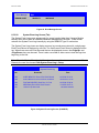
1
®
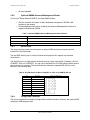
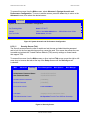
Intel Server Board S1200BT
Technical Product Specification
Intel order number G13326-003
Revision 1.0
March, 2011
Enterprise Platforms and Services Division
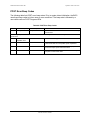
Revision History
Intel®Server Board S1200BT TPS
Revision History
Date
July 2010
November 2010
January 2011
January 2011
March 2011
Revision Number
0.3
0.5
0.7
0.9
1.0
Modifications
Initial release.
Updated the hardware info and SE SKU.
Updated S1200BTS info and BIOS setup page.
Updated S1200BT video mode.
Corrected typos.
ii
Revision 1.0
Intel order number G13326-003
Intel®Server Board S1200BT TPS
Disclaimers
Disclaimers
®
Information in this document is provided in connection with Intel products. No license, express or implied, by
estoppel or otherwise, to any intellectual property rights is granted by this document. Except as provided in Intel‘s
®
®
Terms and Conditions of Sale for such products, Intel assumes no liability whatsoever, and Intel disclaims any
®
express or implied warranty, relating to sale and/or use of Intel products including liability or warranties relating to
fitness for a particular purpose, merchantability, or infringement of any patent, copyright or other intellectual property
®
®
right. Intel products are not intended for use in medical, life saving, or life sustaining applications. Intel may make
changes to specifications and product descriptions at any time, without notice.
Designers must not rely on the absence or characteristics of any features or instructions marked ―reserved‖ or
®
―undefined‖. Intel reserves these for future definition and shall have no responsibility whatsoever for conflicts or
incompatibilities arising from future changes to them.
Information provided in this document may be incomplete (as denoted by TBD). Revised information will be
published in a later release of this document and when the related product is made available.
®
The Intel Server Board S1200BT may contain design defects or errors known as errata which may cause the
product to deviate from published specifications. Current characterized errata are available on request.
Intel Corporation server boards contain a number of high-density VLSI and power delivery components that need
adequate airflow to cool. Intel‘s own chassis are designed and tested to meet the intended thermal requirements of
these components when the fully integrated system is used together. It is the responsibility of the system integrator
®
that chooses not to use Intel developed server building blocks to consult vendor datasheets and operating
parameters to determine the amount of airflow required for their specific application and environmental conditions.
Intel Corporation cannot be held responsible if components fail or the server board does not operate correctly when
used outside any of their published operating or non-operating limits.
Intel, Pentium, Itanium, and Xeon are trademarks or registered trademarks of Intel Corporation.
*Other brands and names may be claimed as the property of others.
Copyright © Intel Corporation 2011.
iii
Revision 1.0
Intel order number G13326-003
Table of Contents
Intel®Server Board S1200BT TPS
Table of Contents
1. Introduction ........................................................................................................................ 1
1.1
Chapter Outline ...................................................................................................... 1
1.2
Server Board Use Disclaimer ................................................................................. 1
2. Overview ............................................................................................................................. 2
2.1
Intel® Server Board S1200BT Feature Set ............................................................. 2
2.2
Server Board Layout .............................................................................................. 4
2.2.1
Server Board Connector and Component Layout ................................................... 5
2.2.2
Intel® Server Board S1200BTL Mechanical Drawings ............................................ 8
2.2.3
Server Board Rear I/O Layout .............................................................................. 14
3. Functional Architecture ................................................................................................... 15
3.1
Processor Sub-System......................................................................................... 16
®
®
3.1.1
Intel Xeon Processor E3-1200 Series ............................................................... 16
3.1.2
Intel® Core™ Processor i3-2100 Series ............................................................... 17
3.1.3
Intel Turbo Boost Technology ............................................................................. 17
3.2
®
Memory Subsystem.............................................................................................. 17
3.2.1
Memory Supported ............................................................................................... 18
3.2.2
Post Error Codes.................................................................................................. 18
3.2.3
Memory Map and Population Rules ...................................................................... 19
3.2.4
Publishing System Memory .................................................................................. 21
3.2.5
Memory RAS Support .......................................................................................... 21
®
3.3
Intel Chipset PCH ............................................................................................... 21
3.4
I/O Sub-system .................................................................................................... 22
3.4.1
Digital Media Interface (DMI) ................................................................................ 22
3.4.2
PCI Express Interface .......................................................................................... 22
3.4.3
Serial ATA Support .............................................................................................. 22
3.4.4
Low Pin Count (LPC) Interface ............................................................................. 23
3.4.5
USB 2.0 Support .................................................................................................. 23
3.5
Optional Intel® SAS RAID Module ........................................................................ 24
3.6
Integrated Baseboard Management Controller ..................................................... 24
3.6.1
Integrated BMC Embedded LAN Channel ............................................................ 26
3.6.2
Optional RMM4 Advanced Management Board.................................................... 27
3.6.3
Serial Ports .......................................................................................................... 27
iv
Revision 1.0
Intel order number G13326-003
Intel®Server Board S1200BT TPS
Table of Contents
3.6.4
Floppy Disk Controller .......................................................................................... 27
3.6.5
Keyboard and Mouse Support .............................................................................. 28
3.6.6
Wake-up Control .................................................................................................. 28
3.7
Video Support ...................................................................................................... 28
3.7.1
Intel® Server Board S1200BTL ............................................................................. 28
3.7.2
Video for Intel Server Board S1200BTS ............................................................. 29
3.8
®
Network Interface Controller (NIC) ....................................................................... 29
3.8.1
Gigabit Ethernet Controller 82574L ...................................................................... 29
3.8.2
Gigabit Ethernet PHY 82579 ................................................................................ 29
3.8.3
MAC Address Definition ....................................................................................... 30
3.9
3.9.1
Intel® I/O Acceleration Technolgy 2 (Intel® I/OAT2) .............................................. 30
Direct Cache Access (DCA) ................................................................................. 30
®
®
3.10
Intel Virtualization Technology for Directed I/O (Intel VT-d) ............................... 30
3.11
TPM (Trusted Platform Module) ........................................................................... 31
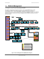
4. Platform Management ...................................................................................................... 32
4.1
Feature Support ................................................................................................... 33
4.1.1
IPMI 2.0 Features................................................................................................. 33
4.1.2
Non-IPMI Features ............................................................................................... 33
4.1.3
New Manageability Features ................................................................................ 34
4.2
Basic and Optional Advanced Management Features .......................................... 35
4.2.1
Enabling Advanced Management Features .......................................................... 36
4.2.2
Keyboard, Video, and Mouse (KVM) Redirection ................................................. 36
4.2.3
Media Redirection ................................................................................................ 38
4.2.4
Embedded Web server ........................................................................................ 39
4.2.5
Embedded Platform Debug .................................................................................. 40
4.2.6
Data Center Management Interface (DCMI) ......................................................... 41
4.2.7
Local Directory Authentication Protocol (LDAP) ................................................... 41
4.3
Thermal Control ................................................................................................... 41
4.3.1
Memory Thermal Throttling .................................................................................. 41
4.3.2
Fan Speed Control ............................................................................................... 42
4.4
Intel® Intelligent Power Node Manager ................................................................. 42
4.4.1
Overview .............................................................................................................. 42
4.4.2
Features ............................................................................................................... 43
4.4.3
Role of Integrated BMC in NM.............................................................................. 44
v
Revision 1.0
Intel order number G13326-003
Table of Contents
Intel®Server Board S1200BT TPS
5. Server Management Capability for Intel® Server Board S1200BTS............................... 46
5.1
5.1.1
Supper I/O............................................................................................................ 46
Key Features of supper I/O .................................................................................. 46
6. BIOS User Interface .......................................................................................................... 47
6.1
6.1.1
BIOS POST Initialization ...................................................................................... 47
BIOS Revision Identification ................................................................................. 47
6.2
HotKeys Supported During POST ........................................................................ 48
6.3
POST Logo Screen/Diagnostic Screen ................................................................ 49
6.4
BIOS Boot Pop-up Menu ...................................................................................... 50
6.5
BIOS Setup Utility ................................................................................................ 50
6.5.1
BIOS Setup Operation ......................................................................................... 50
6.5.2
BIOS Setup Utility Screens .................................................................................. 53
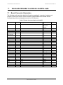
7. Connector/Header Locations and Pin-outs .................................................................... 90
7.1
Board Connector Information ............................................................................... 90
7.2
Power Connectors ................................................................................................ 91
7.3
System Management Headers ............................................................................. 92
7.3.1
Intel® Remote Management Module 4 (Intel® RMM4) Lite connetor and Dedicated
NIC connector .................................................................................................................... 92
7.3.2
LPC/IPMB Header ................................................................................................ 93
7.3.3
HSBP Header....................................................................................................... 93
7.3.4
SGPIO Header ..................................................................................................... 93
7.4
Front Control Panel Connector ............................................................................. 93
7.4.1
Power Button ....................................................................................................... 94
7.4.2
Reset Button ........................................................................................................ 95
7.4.3
System Status Indicator LED ............................................................................... 95
7.5
I/O Connectors ..................................................................................................... 96
7.5.1
VGA Connector .................................................................................................... 96
7.5.2
Rear NIC and USB connector .............................................................................. 96
7.5.3
SATA ................................................................................................................... 97
7.5.4
SAS Connectors................................................................................................... 97
7.5.5
Serial Port Connectors ......................................................................................... 98
7.5.6
USB Connector .................................................................................................... 99
7.6
PCI Express* Slot/PCI Slot/Riser Card Slot ........................................................ 100
7.7
Fan Headers ...................................................................................................... 103
8. Jumper Blocks ................................................................................................................ 104
vi
Revision 1.0
Intel order number G13326-003
Intel®Server Board S1200BT TPS
8.1
Table of Contents
CMOS Clear and Password Reset Usage Procedure......................................... 105
8.1.1
Clearing the CMOS ............................................................................................ 106
8.1.2
Clearing the Password ....................................................................................... 106
8.2
Integrated BMC Force Update Procedure (Only for The Intel® Server Board
S1200BTL) .......................................................................................................................... 107
8.3
ME Force Update Jumper .................................................................................. 107
8.4
BIOS Recovery Jumper...................................................................................... 108
®
9. Intel Light Guided Diagnostics .................................................................................... 109
9.1
System Status LED (Only for S1200BTL)........................................................... 109
9.2
Post Code Diagnostic LEDs ............................................................................... 109
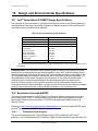
10. Design and Environmental Specifications ................................................................... 111
®
10.1
Intel Server Board S1200BT Design Specifications .......................................... 111
10.2
Board-level Calculated MTBF ............................................................................. 111
10.2.1
10.3
Processor Power Support .................................................................................. 111
Power Supply Output Requirements .................................................................. 112
10.3.1
Grounding .......................................................................................................... 113
10.3.2
Standby Outputs ................................................................................................ 113
10.3.3
Remote Sense ................................................................................................... 113
10.3.4
Voltage Regulation ............................................................................................. 113
10.3.5
Dynamic Loading ............................................................................................... 113
10.3.6
Capacitive Loading ............................................................................................. 114
10.3.7
Closed-loop Stability........................................................................................... 114
10.3.8
Common Mode Noise......................................................................................... 114
10.3.9
Ripple / Noise ..................................................................................................... 114
10.3.10 Timing Requirements ......................................................................................... 114
10.3.11 Residual Voltage Immunity in Standby Mode ..................................................... 117
10.3.12 Protection Circuits .............................................................................................. 117
Appendix A: Integration and Usage Tips ............................................................................ 119
Appendix B: Integrated BMC Sensor Tables ...................................................................... 120
Appendix C: POST Code Diagnostic LED Decoder ............................................................ 129
Appendix D: POST Code Errors ........................................................................................... 133
Appendix E: Supported Intel® Server Chassis .................................................................... 136
Glossary ................................................................................................................................ 137
Reference Documents .......................................................................................................... 141
vii
Revision 1.0
Intel order number G13326-003
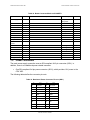
List of Figures
Intel®Server Board S1200BT TPS
List of Figures
Figure 1. Intel® Server Board S1200BTL Picture......................................................................... 4
Figure 2. Intel® Server Board S1200BTS Picture ........................................................................ 5
Figure 3. Intel® Server Board S1200BTL Layout ......................................................................... 6
®
Figure 4. Intel Server Board S1200BTS Layout ......................................................................... 7
Figure 5. Intel® Server Board S1200BTL – Hole and Component Positions ................................ 9
Figure 6. Intel® Server Board S1200BTL – Major Connector Pin Location (1 of 2) .................... 10
Figure 7. Intel® Server Board S1200BTL – Major Connector Pin Location (2 of 2) .................... 11
Figure 8. Intel® Server Board S1200BTL – Primary Side Keepout Zone ................................... 12
Figure 9. Intel® Server Board S1200BTL – Secondary Side Keepout Zone............................... 13
Figure 10. Intel® Server Board S1200BT Rear I/O Layout ......................................................... 14
Figure 11. Intel® Server Board S1200BTL Functional Block Diagram ....................................... 15
Figure 12. Intel® Server Board S1200BTS Functional Block Diagram ....................................... 16
Figure 13. Integrated BMC Hardware ....................................................................................... 26
Figure 14. Server Management Bus (SMBUS) Block Diagram.................................................. 32
Figure 15. Main Screen ............................................................................................................. 56
Figure 16. Advanced Screen ..................................................................................................... 59
Figure 17. Processor Configuration Screen .............................................................................. 62
Figure 18. Memory Configuration Screen.................................................................................. 68
Figure 19. Mass Storage Controller Configuration Screen ........................................................ 71
Figure 20. Serial Port Configuration Screen .............................................................................. 72
Figure 21. USB Configuration Screen ....................................................................................... 73
Figure 22. PCI Configuration Screen ........................................................................................ 74
Figure 23. System Acoustic and Performance Configuration .................................................... 75
Figure 24. Security Screen........................................................................................................ 75
Figure 25. Server Management Screen (S1200BTL) ................................................................ 76
Figure 26. Server Management Screen (S1200BTS) ................................................................ 77
Figure 27. Console Redirection Screen..................................................................................... 77
Figure 28. System Information Screen (S1200BTL) .................................................................. 78
Figure 29.System Information Screen (S1200BTS) .................................................................. 79
Figure 30. BMC LAN Configuration Screen (S1200BTL)........................................................... 80
Figure 31. Hardware Monitor Screen, Auto Fan Control (S1200BTS) ....................................... 81
Figure 32. Hardware Monitor Screen, Manual Fan Control (S1200BTS) ................................... 81
viii
Revision 1.0
Intel order number G13326-003
Intel®Server Board S1200BT TPS
List of Figures
Figure 33. Realtime Teperature and Voltage Status Screen (S1200BTS) ................................. 82
Figure 34. Boot Options Screen ................................................................................................ 83
Figure 35. Hard Disk Order Screen ........................................................................................... 84
Figure 36. CDROM Order Screen ............................................................................................. 84
Figure 37. Floppy Order Screen ................................................................................................ 85
Figure 38. Network Device Order Screen.................................................................................. 85
Figure 39. BEV Device Order Screen ....................................................................................... 86
Figure 40. Add EFI Boot Option Screen .................................................................................... 86
Figure 41. Delete EFI Boot Option Screen ................................................................................ 87
Figure 42. Boot Manager Screen .............................................................................................. 87
Figure 43. Error Manager Screen ............................................................................................. 88
Figure 44. System Event Log Screen (S1200BTS) ................................................................... 88
Figure 45. Exit Screen .............................................................................................................. 89
Figure 46. Jumper Blocks (J4A2, J1F1, J1F3, J1F2, and J1E2) on S1200BTL ....................... 104
Figure 47. Jumper Blocks (J2G1, J1G1, J1H3, and J2J1) on S1200BTS ............................... 105
Figure 48. POST Code Diagnostic LED Location .................................................................... 110
Figure 49. Output Voltage Timing ........................................................................................... 115
Figure 50. Turn On/Off Timing (Power Supply Signals) .......................................................... 116
ix
Revision 1.0
Intel order number G13326-003
List of Tables
Intel®Server Board S1200BT TPS
List of Tables
Table 1. Intel® Server Board S1200BT Feature Set .................................................................... 2
Table 2. Major Board Components ............................................................................................. 6
Table 3. Major Board Components ............................................................................................. 7
Table 4. Memory Configuration Table ....................................................................................... 20
Table 5. UDIMM memory configuration rule .............................................................................. 20
Table 6. UDIMM Maximum configuration .................................................................................. 20
Table 7. Optional RMM4 Advanced Management Board Features............................................ 27
Table 8. Serial B Header (J1B2 on S1200BTL or J8A1 on S1200BTS) Pin-out ........................ 27
Table 9. Video Modes ............................................................................................................... 28
Table 10. Dual Video Modes ..................................................................................................... 29
Table 11. Basic and Advanced Management Features ............................................................. 35
Table 12. NM Features ............................................................................................................. 43
Table 13. POST HotKeys Recognized ...................................................................................... 49
Table 14. BIOS Setup Page Layout .......................................................................................... 51
Table 15. BIOS Setup: Keyboard Command Bar ...................................................................... 52
Table 16. Screen Map ............................................................................................................... 54
Table 17. Board Connector Matrix on S1200BTL ...................................................................... 90
Table 18. Board Connector Matrix on S1200BTS ..................................................................... 91
Table 19. Baseboard Power Connector Pin-out (J9G1) ............................................................ 91
Table 20. SSI Processor 8-PIN Power Connector Pin-out (J9A1) ............................................. 92
Table 21. Intel® RMM4 lite Connector Pin-out (J4B1) ................................................................ 92
Table 22. Dedicated NIC connector for RMM4 .......................................................................... 92
Table 23. LPC/IPMB Header Pin-out (J1H5) ............................................................................. 93
Table 24. HSBP Header Pin-out (J1J2) .................................................................................... 93
Table 25. SGPIO Header Pin-out (J1J3 on S1200BTL and J2J2 on S1200BTS) ...................... 93
Table 26. Front Panel SSI Standard 24-pin Connector Pin-out (J1C1 on S1200BTL or J1C2 on
S1200BTS) ......................................................................................................................... 93
Table 27. System Status LED Indicator States ......................................................................... 95
Table 28. VGA Connector Pin-out ............................................................................................. 96
Table 29. RJ-45 10/100/1000 NIC Connector Pin-out ............................................................... 96
Table 30. RJ-45 10/100/1000 NIC Connector Pin-out (J6A1).................................................... 97
Table 31. 6Gb/s SATA Connector Pin-Out ................................................................................ 97
Table 32. 3Gb/s SATA Connector Pin-out ................................................................................ 97
x
Revision 1.0
Intel order number G13326-003
Intel®Server Board S1200BT TPS
List of Tables
Table 33. SAS Connector Pin-out (J2H1).................................................................................. 98
Table 34. External Serial A Port Pin-out (J8A1) ........................................................................ 98
Table 35. Internal 9-pin Serial B Header Pin-out (J1B2) ........................................................... 98
Table 36. Internal USB Connector Pin-out ( J1E1, J1D1) ......................................................... 99
Table 37. Pin-out of Internal USB Connector for low-profile Smart module (J3F2).................... 99
Table 38. Pin-out of adaptive riser slot/PCI Express slot 6 ...................................................... 100
Table 39. Three PCI Express* x8 connectors (J2B2, J3B1 and J4B2) .................................... 102
Table 40. One PCI X32 connector (J1B1) ............................................................................... 102
Table 41. SSI 4-pin Fan Header Pin-out ................................................................................. 103
Table 42. Server Board Jumpers (J1F1, J1F2, J1F3, J1E2, and J4A2) on S1200BTL ............ 104
Table 43. Server Board Jumpers (J2G1, J1G1, J1H3, and J2J1) on S1200BTS .................... 105
Table 44. Front Panel LED Behavior Summary....................................................................... 109
Table 45. Server Board Design Specifications ........................................................................ 111
Table 46. Intel® Xeon® Processor TDP Guidelines .................................................................. 112
Table 47. 350-W Load Ratings ............................................................................................... 112
Table 48. Voltage Regulation Limits........................................................................................ 113
Table 49. Transient Load Requirements ................................................................................. 113
Table 50. Capacitve Loading Conditions ................................................................................. 114
Table 51. Ripple and Noise ..................................................................................................... 114
Table 52. Output Voltage Timing ............................................................................................ 115
Table 53. Turn On/Off Timing ................................................................................................. 116
Table 54. Over-Current Protection (OCP) ............................................................................... 117
Table 55. Over-voltage Protection (OVP) Limits ..................................................................... 117
Table 56. BMC Core Sensors ................................................................................................. 122
Table 57. POST Progress Code LED Example ....................................................................... 129
Table 58. POST Progress Codes ............................................................................................ 129
Table 59. POST Error Codes and Messages .......................................................................... 133
Table 60. POST Error Beep Codes ......................................................................................... 135
xi
Revision 1.0
Intel order number G13326-003
List of Tables
Intel®Server Board S1200BT TPS
<This page is intentionally left blank.>
xii
Revision 1.0
Intel order number G13326-003
Intel®Server Board S1200BT TPS
1.
Introduction
Introduction
This Technical Product Specification (TPS) provides board specific information detailing the
features, functionality, and high-level architecture of the Intel® Server Board S1200BT.
In addition, you can obtain design-level information for specific subsystems by ordering the
External Product Specifications (EPS) or External Design Specifications (EDS) for a given
subsystem. EPS and EDS documents are not publicly available and must be ordered through
your local Intel® representative.
1.1
Chapter Outline
This document is divided into the following chapters:
1.2
Chapter 1 – Introduction
Chapter 2 – Server Board Overview
Chapter 3 – Functional Architecture
Chapter 4 – Platform Management
Chapter 5 – Server Management Capability
Chapter 6 – BIOS User Interface
Chapter 7 – Connector/Header Locations and Pin-outs
Chapter 8 – Jumpers Blocks
Chapter 9 – Intel® Light-Guided Diagnostics
Chapter 10 – Design and Environmental Specifications
Appendix A – Integration and Usage Tips
Appendix B – Integrated BMC Sensor Tables
Appendix C – POST Code Diagnostic LED Decoder
Appendix D – POST Code Errors
Appendix E – Supported Intel® Server Chassis
Glossary
Reference Documents
Server Board Use Disclaimer
Intel Corporation server boards contain a number of high-density VLSI and power delivery
components that need adequate airflow to cool. Intel® ensures through its own chassis
development and testing that when Intel® server building blocks are used together, the fully
integrated system meets the intended thermal requirements of these components. It is the
responsibility of the system integrator who chooses not to use Intel® developed server building
blocks to consult vendor datasheets and operating parameters to determine the amount of
airflow required for their specific application and environmental conditions. Intel Corporation
cannot be held responsible if components fail or the server board does not operate correctly
when used outside any of their published operating or non-operating limits.
1
Revision 1.0
Intel order number G13326-003
Overview
Intel®Server Board S1200BT TPS
2.
Overview
The Intel® Server Board S1200BT is a monolithic printed circuit board (PCB) with features
designed to support entry-level severs. It has two board SKUs, namely S1200BTL
and S1200BTS.
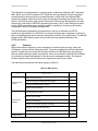
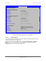
Intel® Server Board S1200BT Feature Set
2.1
®
Table 1. Intel Server Board S1200BT Feature Set
Feature
Processor
Memory
Chipset
Description of S1200BTL
®
®
Support for one Intel Xeon Processor E3®
1200 Series or Intel Core™ Processor i32100 Series in FC-LGA 1155 socket package.
Description of S1200BTS
®
®
Support for one Intel Xeon Processor E3®
1200 Series or Intel Core™ Processor i32100 Series in FC-LGA 1155 socket package.
2.5 GT/s point-to-point DMI interface
to PCH
2.5 GT/s point-to-point DMI interface
to PCH
LGA 1155 pin socket
LGA 1155 pin socket
Two memory channels with support for
1066/1333 MHz ECC Unbuffered (UDIMM)
DDR3.
Up to 2 UDIMMs per channel
32 GB max with x8 ECC UDIMM (2
Gb DRAM)
Two memory channels with support for
1066/1333 MHz ECC Unbuffered (UDIMM)
DDR3.
®
Up to 2 UDIMMs per channel 32 GB
max with x8 ECC UDIMM (2 Gb
DRAM)
®
Support for Intel C204 Platform Controller Hub Support for Intel C202 Platform Controller
(PCH) chipset
Hub (PCH) chipset
ServerEngines* LLC Pilot III BMC controller
(Integrated BMC)
I/O
External connections:
External connections:
DB-15 video connectors
DB-15 video connectors
DB-9 serial Port A connector
DB-9 serial Port A connector
Four ports on two USB/LAN combo
connectors at rear of board
Four ports on two USB/LAN combo
connectors at rear of board
Internal connections:
Internal connections:
Two USB 2x5 pin headers, each
supporting two USB 2.0 ports
Two USB 2x5 pin headers, each
supporting two USB 2.0 ports
One 2x5 Serial Port B headers
One 2x5 Serial Port B headers
Two 6Gb/s SATA ports and four
3Gb/s SATA ports
Six 3Gb/s SATA ports
One SAS mezzanine slot for optional
SAS module
2
Revision 1.0
Intel order number G13326-003
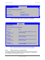
Intel®Server Board S1200BT TPS
Overview
Feature
Add-in PCI Card,
PCI Express* Card
Description of S1200BTL
Description of S1200BTS
Slot1: One 5V PCI 32 bit/33 MHz
connector
Slot4: One 5V PCI 32 bit/33 MHz
connector
Slot3: One PCI Express* Gen2 x8 (x4
throughput) connector
Slot5: One PCI Express* Gen2 x8
(x4 throughput) connector
Slot4: One PCI Express* Gen2 x8 (x4
throughput) connector
Slot6: One PCI Express* Gen2 x8
(x8 throughput) connector
Slot5: One PCI Express* Gen2 x8 (x4
throughput) connector
Slot7: One PCI Express* Gen2 x16
(x8 throughput) connector
Slot6: One PCI Express* Gen2 x16
(x8 throughput) connector
System Fan
Support
Five 4-pin fan headers supporting four system
fans and one processor
Four 4-pin fan headers supporting four
system fans and one processor
Video
Onboard ServerEngines* LLC Pilot III BMC
Controller
Silicon Motion SM712GX04LF02-BA
Onboard Hard
Drive
External 32MB (or above) DDR3
800MHz memory
Support for six Serial ATA II hard drives
through six onboard SATA II connectors with
SW RAID 0, 1, 5, and 10
Support for six Serial ATA II hard drives
through six onboard SATA II connectors with
SW RAID 0, 1, 5 and 10.
Up to four SAS hard drives through optional
®
Intel SAS Entry RAID Module card
Six 3Gb/s SATA ports
Two 6Gb/s SATA ports and four 3Gb/s SATA
ports
RAID Support
LAN
Server
Management
®
Intel Embedded Server RAID
Technology II through onboard
SATA connectors provides SATA
RAID 0, 1, and 10 and optional RAID
®
5 support provided by the Intel
RAID Activation Key AXXRAKSW5.
®
Intel Rapid Storage RAID through
onboard SATA connectors provides
SATA RAID 0, 1, 5, and 10.
Intel Embedded Server RAID
Technology II through onboard SATA
connectors provides SATA RAID 0, 1,
and 10 and optional RAID 5 support
®
provided by the Intel RAID Activation
Key AXXRAKSW5
Intel Rapid Storage RAID through
onboard SATA connectors provides
SATA RAID 0, 1, 5, and 10
One optional internal SAS module
connector which supports
AXXRMS2AF040, AXXRMS2LL040,
and AXX4SASMOD
®
®
One Gigabit Ethernet device 82574L connect
to PCI-E x1 interfaces on the PCH
One Gigabit Ethernet device 82574L connect
to PCI-E x1 interfaces on the PCH
One Gigabit Ethernet PHY 82579 connected to
PCH through PCI-E x1 interface
One Gigabit Ethernet PHY 82579 connected
to PCH through PCI-E x1 interface
Onboard LLC Pilot III Controller (iBMC)
—
Integrated Baseboard Management
Controller (Integrated BMC), IPMI 2.0
compliant
Integrated 2D video controller on PCIE x1
®
Optional Intel Remote Management Module 4
®
(RMM4) Lite only or Intel Remote
Management Module 4 (RMM4)
Security
TPM module connector
TPM module connector
3
Revision 1.0
Intel order number G13326-003
Overview
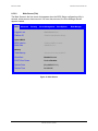
2.2
Intel®Server Board S1200BT TPS
Server Board Layout
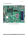
®
Figure 1. Intel Server Board S1200BTL Picture
4
Revision 1.0
Intel order number G13326-003
Intel®Server Board S1200BT TPS
Overview
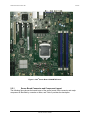
®
Figure 2. Intel Server Board S1200BTS Picture
2.2.1
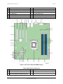
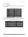
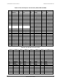
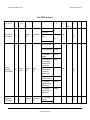
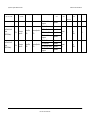
Server Board Connector and Component Layout
The following figure shows the board layout of the server board. Each connector and major
component is identified by a number or letter, and Table 2 provides the description.
5
Revision 1.0
Intel order number G13326-003
Overview
Intel®Server Board S1200BT TPS
®
Figure 3. Intel Server Board S1200BTL Layout
Table 2. Major Board Components
Description
Description
A
Slot 1, 32 Mbit/33 MHz PCI
R
System FAN2 and System FAN3 Connector
B
TPM
S
CPU connector
C
Slot 3/4, PCI Express* Gen2 x4 (x8 connector)
T
CPU Fan connector
D
Slot 5, PCI Express* Gen2 x4 (x8 connector)
U
USB connector for smart module
E
Slot 6, PCI Express* Gen2 x8 (x16 connector)
V
SAS Module connector
F
Chassis Intrusion
W
IPMB
G
SATA_KEY
X
SYS_FAN_1
H
Two Ethernet and Dual USB COMBO
Y
HSBP
I
Video port
Z
SATA_SGPIO
J
External Serial port
AA
Internal Serial Connector
K
RMM4 Lite Connector
BB
Front Panel Connector
6
Revision 1.0
Intel order number G13326-003
Intel®Server Board S1200BT TPS
Overview
Description
Description
L
CPU Power Connector
CC
HDD LED
M
SYS_FAN_4
DD
Internal USB Connector
N
RMM4 Dedicated NIC connector
EE
CMOS battery
O
Four DIMM Slots
FF
Four 3Gb/s SATA ports
P
P/S AUX
GG
Two 6Gb/s SATA ports
Q
MAIN POWER
HH
Smart module
®
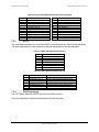
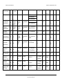
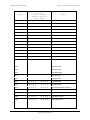
Figure 4. Intel Server Board S1200BTS Layout
Table 3. Major Board Components
Description
Description
A
Slot 4, 32 Mbit/33 MHz PCI
N
SYS FAN 1
B
Slot 5. PCI Express* Gen2 x8 (x8 connector);
Slot 6, PCI Express* Gen2x4 (x8 connector).
O
CPU connector
7
Revision 1.0
Intel order number G13326-003
Overview
Intel®Server Board S1200BT TPS
Description
Description
C
SATA_KEY
P
CPU Fan connector
D
Slot 7, PCI Express* Gen2 x8 (x16 connector)
Q
Chassis Intrusion
E
Ethernet and Dual USB COMBO
R
SATA_SGPIO
F
Ethernet and Dual USB COMBO
S
SYS_FAN_3
G
Video port
T
Six 3Gb/s SATA ports
H
External Serial port
U
Low profile USB connector
I
CPU Power connector
V
Internal USB
J
SYS_FAN_2
W
CMOS battery
K
DIMM slots
X
Front Panel
L
MAIN power connector
Y
HDD LED
M
TPM connector
2.2.2
Intel® Server Board S1200BTL Mechanical Drawings
8
Revision 1.0
Intel order number G13326-003
Intel®Server Board S1200BT TPS
Overview
®
Figure 5. Intel Server Board S1200BTL – Hole and Component Positions
9
Revision 1.0
Intel order number G13326-003
Overview
Intel®Server Board S1200BT TPS
®
Figure 6. Intel Server Board S1200BTL – Major Connector Pin Location (1 of 2)
10
Revision 1.0
Intel order number G13326-003
Intel®Server Board S1200BT TPS
Overview
®
Figure 7. Intel Server Board S1200BTL – Major Connector Pin Location (2 of 2)
11
Revision 1.0
Intel order number G13326-003
Overview
Intel®Server Board S1200BT TPS
®
Figure 8. Intel Server Board S1200BTL – Primary Side Keepout Zone
12
Revision 1.0
Intel order number G13326-003
Intel®Server Board S1200BT TPS
Overview
®
Figure 9. Intel Server Board S1200BTL – Secondary Side Keepout Zone
13
Revision 1.0
Intel order number G13326-003
Overview
2.2.3
Intel®Server Board S1200BT TPS
Server Board Rear I/O Layout
The following figure shows the layout of the rear I/O components for the server board.
A
Serial Port A
C
NIC Port 1 (1 Gb) and Dual USB Port
Connector
B
Video
D
NIC port 2 (1 Gb) and Dual USB Port
Connector
®
Figure 10. Intel Server Board S1200BT Rear I/O Layout
14
Revision 1.0
Intel order number G13326-003
Intel®Server Board S1200BT TPS
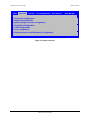
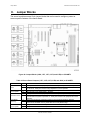
3.
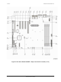
Functional Architecture
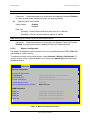
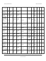
Functional Architecture
The architecture and design of the Intel® Server Board S1200BT is based on the Intel® C202
Chipset. The chipset is designed for systems based on the Intel® Xeon® processor in the FCLGA 1155 socket package.
The Intel® Server Board S1200BTL uses Intel® C204 Chipset and the Intel® Server Board
S1200BTS uses Intel® C202 Chipset.
The Intel® Xeon® Processor E3-1200 Series are made up of multi-core processors based on the
32nm processor technology. The Intel® Core™ Processor i3-2100 is made up of dual-core
processors based on the 32nm processor technology.
This chapter provides a high-level description of the functionality associated with each chipset
component and the architectural blocks that make up the server board.
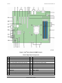
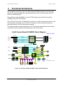
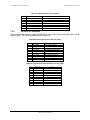
Intel® Server Board S1200BTL Block Diagram
ATX - 12" x 9.6"
(x16 connector)
PCIe Gen2 x8
Slot 6
Intel® Xeon®
Processor
E3-1200
(x8 connector)
PCIe Gen2 x4
Slot 5
(x8 connector)
PCIe Gen2 x4
Slot 4
DDR3 (Channel A)
4 Unbuffered
DIMMs
Knoxvill
Socket H2
DDR3 (Channel B)
PCIe Gen2 x4
Mezzanine Module
A1
A0
Ch A
XDP
B1
B0
Ch B
x4 DMI Gen2
Dual GbE
Lewisville
(PCIe Gen1 x1 in physical)
GLCI
(x8 connector)
PCIe Gen2 x4
Slot 3
Intel® C204
PCI
GbE
PHY
GbE
Hartwell
PCIe Gen1 x1
GbE
PCI 32/33
Slot 1
SPI
RMII
SPI
PCIe Gen1 x1
FLASH
FLASH
SPI
BIOS Flash
SATA-III
GbE
2
4
12
BMC Boot
Flash
DDR3
LPC
BMC
Zoar
SATA 6G
SERIAL 2
Internal
Header
0
1
TPM
SATA 3G
RMM4 LITE
Module
optional
on-board
USB
1.1
USB
2.0
USB 2.0
SATA-II
2
3
4
2
2
2
2
5
USB
Internal USB
Header x2
RGMII
VIDEO
Rear I/O
VGA Port
SERIAL 1
Rear I/O
COM Port
Notes:
1. Video integrated into BMC.
USB
Type-A
Rear I/O USB
I/O Module
Header
Ports x2
RMM4 Dedicated
NIC Module
®
Figure 11. Intel Server Board S1200BTL Functional Block Diagram
Revision 1.0
15
Intel order number G13326-003
Functional Architecture
Intel®Server Board S1200BT TPS
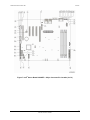
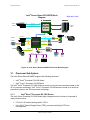
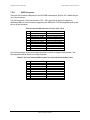
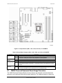
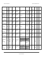
Intel® Server Board S1200BTS Block
Diagram
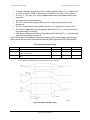
VRD 12.0
VCORE
VTT
VSA
ATX – 9.6" x 9.6"
VPLL
MEM
VTT
MEM VRD 12.0
(x16 connector)
PCIe Gen2 x8
Slot 7
Intel® Xeon®
Processor
E3-1200
(x8 connector)
PCIe Gen2 x8
Slot 6
DDR3 (Channel A)
4 Unbuffered
DIMMs
Knoxvill
Socket H2
DDR3 (Channel B)
A1
A0
Ch A
XDP
B1
B0
Ch B
x4 DMI Gen2
Dual GbE
Lewisville
(PCIe Gen1 x1 in physical)
GLCI
(x8 connector)
Slot 5
PCIe Gen2 x4
GbE
PHY
Misc
VR s
GbE
PCI
Slot 4
PCI 32/33
PCIe Gen1 x1
Cougarpoint
GbE
Hartwell
GbE
SM712
SPI
VIDEO
Rear I/O
VGA Port
FLASH
BIOS Flash
6
12
LPC
SIO
W83627DHGP
SATA 3G
SATA-II
0
1
TPM
2
3
TPM
Header
USB 2.0
4
5
2
Internal USB
Header x2
Type-A
Header
2
2
USB
USB
SERIAL 1
Rear I/O
COM Port
SERIAL 2
Internal
Header
Rear I/O USB
Ports x2
®
Figure 12. Intel Server Board S1200BTS Functional Block Diagram
3.1
Processor Sub-System
The Intel® Server Board S1200BT supports the following processor:
Intel® Xeon® Processor E3-1200 Series.
®
Intel Core™ Processor i3-2100 Series
®
®
The Intel Xeon Processor E3-1200 Series are made up of multi-core processors based on the
32 nm processor technology. Intel® Core™ Processor i3-2100 Series are made up of dual-core
processors based on the 32nm processor technology.
3.1.1
Intel® Xeon® Processor E3-1200 Series
The Intel® Xeon® Processor E3-1200 Series highly integrated solution variant is composed of
quad processor cores.
FC-LGA 1155 socket package with 2.5 GT/s.
Up to 95 W Thermal Design Power (TDP); processors with higher TDP are
not supported.
16
Revision 1.0
Intel order number G13326-003
Intel®Server Board S1200BT TPS
Functional Architecture
The server board does not support previous generations of the Intel® Xeon® processors. The
list of supported processors may be found at http://serverconfigurator.intel.com.
Note: The workstation processor is not supported in this platform.
Intel® Core™ Processor i3-2100 Series
3.1.2
®
The Intel Core™ Processor i3-2100 Series highly integrated solution variant is composed of
Duo cores.
FC-LGA 1155 socket package with 2.5 GT/s.
Up to 65 W Thermal Design Power (TDP); processors with higher TDP are
not supported.
®
The server board does not support previous generations of the Intel Core™ Processor
i3 Series.
The list of supported processors may be found at http://serverconfigurator.intel.com.
Intel® Turbo Boost Technology
3.1.3
Intel® Turbo Boost Technology is featured on certain processors in the Intel® Xeon® Processor
E3-1200 Series. Intel® Turbo Boost Technology opportunistically and automatically allows the
processor to run faster than the marked frequency if the processor is operating below power,
temperature, and current limits. This results in increased performance for both multi-threaded
and single-threaded workloads.
Intel® Turbo Boost Technology operation:
Turbo Boost operates under Operating System control – It is only entered when the
operating system requests the highest (P0) performance state.
Turbo Boost operation can be enabled or disabled in BIOS Setup.
Turbo Boost converts any available power and thermal headroom into a higher
frequency on active cores. At nominal marked processor frequency, many applications
consume less than the rated processor power draw.
Turbo Boost availability is independent of the number of active cores.
Maximum Turbo Boost frequency depends on the number of active cores and varies by
processor configuration.
The amount of time the system spends in Turbo Boost operation depends on workload,
operating environment, and platform design.
If the processor supports the Intel® Turbo Boost Technology feature, the BIOS Setup provides
an option to enable or disable this feature. The default state is enabled.
3.2
Memory Subsystem
The Intel® Xeon® Processor E3-1200 series or Intel® Core™ Processor i3-2100 has an
Integrated Memory Controller (IMC) in its package. Each processor produces up to two DDR3
channels of memory. Each DDR3 channel in the IMC supports up to two UDIMM slots. The
DDR3 UDIMM frequency can be 1066/1333 MHz. Only ECC memory is supported on
this platform.
Revision 1.0
17
Intel order number G13326-003
Functional Architecture
Intel®Server Board S1200BT TPS
The memory channels are named as ―Channel A‖ and ―Channel B‖.
The memory slots are named as ―Slot1‖ and ―Slot2‖ on each channel. Slot1will be the
farthest from the processor socket.
DIMMs are named to reflect the channel and slot in which they are installed:
3.2.1
o
Channel A, Slot1 is ―DIMM_A1‖.
o
Channel A, Slot2 is ―DIMM_A2‖.
o
Channel B, Slot1 is ―DIMM_B1‖.
o
Channel B, Slot2 is ―DIMM_B2‖.
Memory Supported
®
The Intel Server Board S1200BT family supports various DDR3 DIMM modules of different
types and sizes and speeds.
In this section, the statements of support are subject to qualification in two ways:
For S1200 Server Boards with an SNB-DT processor, the Server Board and the BIOS
may support:
DIMMs composed of Dynamic Random Access Memory (DRAM) chips using 1 Gb, 2
Gb, or 4 Gb technology
DIMMs using x8 DRAM technology only
DIMMs organized as Single Rank (SR) or Dual Rank (DR)
DIMM sizes of 1 GB, 2 GB, 4 GB, or 8 GB
DIMM speeds of 1066 or 1333 MT/s (megatransfers/second)
Only Unregistered (Unbuffered) DIMMs (UDIMMs) are supported
Only Error Correction Code (ECC) enabled DIMMs are supported
UDIMMs may or may not have thermal sensors
Note: UDIMMs must be ECC, and may or may not have thermal sensors.
S1200BT BIOS has the following limitations:
3.2.2
No support for LV DIMMs
No support for RDIMMs
All channels in a system will run at the fastest common frequency
Mixing ECC and non-ECC UDIMMs anywhere on the platform is not supported
Static Closed Loop Thermal Throttling (CLTT) supported via BMC (requires ECC DIMMs
with thermal sensor)
Post Error Codes
The range {0xE0 - 0xEF} of POST codes is used for memory errors in early POST. In late
POST, this same range of POST code values is used for reporting other system errors.
0xE8 - No Usable Memory Error: If no usable memory is available, the BIOS emits a
beep code and displays POST Diagnostic LED code 0xE8 and halts the system.
18
Revision 1.0
Intel order number G13326-003
Intel®Server Board S1200BT TPS
Functional Architecture
This can also occur if all memory in the system fails and/or has become disabled during
memory initialization. For example, if a DDR3 DIMM has no SPD information, the BIOS
treats the DIMM slot as if no DDR3 DIMM is present on it. Therefore, if this is the only
DDR3 DIMM installed in the system, there is no usable memory, and the BIOS goes to a
memory error code 0xE8 as described above.
0xEA - Channel Training Error: If the memory initialization process is unable to
properly perform the Data/Data Strobe timing training on a memory channel, the BIOS
emits a beep code and displays POST Diagnostic LED code 0xEA momentarily during
the beeping. If there is usable memory in the system on other channels, POST memory
initialization continues. Otherwise, the system beeps and halts with POST Diagnostic
LED code 0xEA staying displayed.
0xEB - Memory Test Error: If a DDR3 DIMM or a set of DDR3 DIMMs on the same
memory channel fails memory testing but usable memory remains available, the BIOS
emits a beep code and displays POST Diagnostic LED code 0xEB momentarily during
the beeping, then continues POST. If all of the memory fails memory testing, then
system memory error code 0xE8 (No Usable Memory) as described above.
0xED - Population Error: If the installed memory contains an invalid DIMM
configuration on any channel in the system, the system beeps and halts with POST
Diagnostic LED code 0xED.
Note: Mixed DIMM configurations are not supported and not validated by Intel®.
3.2.3
Memory Map and Population Rules
The overall configuration is a single processor with two channels, and two DIMM slots on each
channel on the Intel® Server Board S1200BT. All memory DIMMs are ECC UDIMMs only, with a
maximum size of 8 GB.
Slot1 must be populated first before Slot2, on either channel.
Channel A and Channel B are independent and are not required to have the same
number of DIMMs installed. Either channel may be used for a single-DIMM
configuration.
o
When only one memory channel is populated, the memory runs in Single
Channel mode, with no interleaving.
o
When both channels are populated identically, the memory runs in Dual Channel
Symmetric mode. The memory is interleaved by full 64-byte cache lines
alternating between channels, i.e. the first entire cache line resides in DIMM_A1,
the second in DIMM_B1, and so on. This allows Adjacent Cache Line Prefetch to
fetch cache lines from both channels simultaneously, approximately doubling the
potential memory bandwidth.
o
When both channels are populated, but with different numbers of DIMMs, Intel®
Flex Memory Technology divides the installed memory into two zones, using
interleaved Dual Channel Symmetric mode as far as the highest address on the
less-populated channel, then using uninterleaved Dual Channel Asymmetric
mode for the remaining memory on the more-populated channel.
The maximum total installed memory size supported is 32 GB, using four 8 GB DIMMs.
Revision 1.0
19
Intel order number G13326-003
Functional Architecture
Intel®Server Board S1200BT TPS
The maximum memory bandwidth is 10.6 GB/s in Single-Channel mode or 21 GB/s in
Dual-Channel Symmetric mode, assuming DDR3 running at 1333 MT/s.
3.2.3.1
Memory Configuration Table
Table 4. Memory Configuration Table
Configuration
1 DIMM
Single Channel
DIMM_A1
DIMM_A2
DIMM_B1
1 DIMM
Single Channel
2 DIMMs
Single Channel
B1 only
Single Channel
A1
Single Channel
A2
Single Channel
2 DIMMs
Single Channel
B1
Single Channel
2 DIMMs
A1
Dual Channel Symmetric Dual Channel
Symmetric
3 DIMMs
Intel®Flex Memory
A1
Dual Channel
Symmetric
3 DIMMs
Intel®Flex Memory
A1
Dual Channel
Symmetric
4 DIMMs
A1
Dual Channel Symmetric Dual Channel
Symmetric
3.2.3.2
DIMM_B2
A1 only
Single Channel
B2
Single Channel
B1
Dual Channel
Symmetric
A2
Dual Channel
Asymmetric
B1
Dual Channel
Symmetric
A2
Dual Channel
Symmetric
B1
Dual Channel
Symmetric
B2
Dual Channel
Asymmetric
B1
Dual Channel
Symmetric
B2
Dual Channel
Symmetric
DIMM Configuration rules
Table 5. UDIMM memory configuration rule
DIMM slots per channel
DIMMs populated per channel
2
1
Speed
1066, 1333
2
2
1066, 1333
Ranks per channel
Single Rank, Dual Rank
Single Rank, Dual Rank
To get the maximum memory size on UDIMM, you get the detailed information from
following table:
Table 6. UDIMM Maximum configuration
Max Memory Possible
Single Rank UDIMM
1Gb DRAM Technology
4GB
(4x 1GB DIMMs)
2Gb DRAM Technology
8GB
(4x 2GB DIMMs)
4Gb DRAM Technology
16GB
(4x 4GB DIMMs)
Dual Rank UDIMMs
8GB
16GB
32GB
20
Revision 1.0
Intel order number G13326-003
Intel®Server Board S1200BT TPS
Max Memory Possible
3.2.4
Functional Architecture
1Gb DRAM Technology
(4x 2GB DIMMs)
2Gb DRAM Technology
(4x 4GB DIMMs)
4Gb DRAM Technology
(4x 8GB DIMMs)
Publishing System Memory
For S1200 Server Boards with an SNB-DT processor, the memory configurations and
population rules are relatively simple. The overall configuration is a single processor/IMC, with
two channels, and two DIMM slots on each channel. All memory DIMMs are ECC UDIMMs only,
with a maximum size of 8 GB.
Slot1 must be populated first before Slot2, on either channel.
Channel A and Channel B are independent and are not required to have the same
number of DIMMs installed. Either channel may be used for a single-DIMM
configuration.
o
3.2.5
When only one memory channel is populated, the memory runs in Single
Channel mode, with no interleaving.
Memory RAS Support
®
For Intel Server Board S1200BT, the form of Memory RAS provided is Error Correction Code
(ECC). ECC uses ―extra bits‖ – 64-bit data in a 72-bit DRAM array – to add an 8-bit calculated
―Hamming Code‖ to each 64 bits of data. This additional encoding enables the memory
controller to detect and report single or double bit errors, and to correct single-bit errors.
There is a specific step in memory initialization in which all of memory is cleared to zeroes
before the ECC function is enabled, in order to bring the ECC codes into agreement with
memory contents.
During operation, in the process of every fetch from memory, the data and ECC bits are
examined for each 64-bit data + 8-bit ECC group. If the ECC computation indicates that a single
bit Correctable Error has occurred, it is corrected and the corrected data is passed on to the
processor. If a double-bit Uncorrectable Error is detected, it cannot be corrected. In each case,
a Correctable or Uncorrectable ECC Error event is generated.
For Correctable Errors, there is a certain tolerance observed, since a Correctable Error can be
generated by something as random as a stray Cosmic Ray impacting the DIMM. Correctable
Errors are counted on a per-DIMM basis, but are just silently recorded until the tolerance
threshold is crossed. The Correctable Error Threshold for Intel® Server Board S1200BT board
is set at 10 events. When the 10th CE occurs, a single Correctable Error event is logged.
3.3
Intel® Chipset PCH
The Intel® C200Series Chipset is designed for use with Intel® Xeon® Processor E3-1200 series
or Intel® Core™ Processor i3-2100 in a UP server platform. The role of the PCH in the Intel®
Server Board S1200BT is to manage the flow of information between its eleven interfaces,
described below:
DMI interface to Processor
PCI Express* Interface
PCI Interface
Serial ATA Interface
LPC Interface to IBMC and TPM
Revision 1.0
21
Intel order number G13326-003
Functional Architecture
Intel®Server Board S1200BT TPS
USB host interface
SMBus Host interface
Serial Peripheral interface
LAN interface
ACPI interface
3.4
I/O Sub-system
Intel® C200 Series PCH provides extensive I/O support.
3.4.1
Digital Media Interface (DMI)
Direct Media Interface (DMI) is the chip-to-chip connection between the processor and C202
chipset. This high-speed interface integrates advanced priority-based servicing allowing for
concurrent traffic and true isochronous transfer capabilities. Base functionality is completely
software-transparent, permitting current and legacy software to operate normally.
3.4.2
PCI Express Interface
The PCI-E configurations for each SKU are defined below:
Intel® Server Board S1200BTL
One PCI-E x16 connector to be used as a x8 link, two PCI-E x8 connectors to be used as a
x4 link and one SAS module connector to be used as a x4 link connected to the PCI-E
ports of the processor. One PCI-E x8 connector to be used as x4 link connected to the PCE ports of PCH.
®
Intel Server Board S1200BTS
One PCI-E x16 connector to be used as x8 link, one PCI-E x8 connectors to be used as a
x8 link connected to the PCI-E ports of the processor. One PCI-E x8 connector to be used
as x4 link connected to the PCI-E ports of PCH.
There is one 32-bit, 33-MHz 5-V PCI slot, common on both SKUs.
Compatibility with the PCI addressing model is maintained to ensure all existing applications
and drivers operate unchanged.
The PCI Express* configuration uses standard mechanisms as defined in the PCI Plug-andPlay specification. The initial recovered clock speed of 1.25 GHz results in 2.5 Gb/s each
direction, which provides a 250-MB/s communications channel in each direction (500 MB/s
total). This is close to twice the data rate of classic PCI. It is a fact that 8b/10b encoding is used
accounts for the 250 MB/s where quick calculations would imply 300 MB/s. The external
graphics ports support 5.0 GT/s speed as well. Operating at 5.0 GT/s results in twice as much
bandwidth per lane as compared to 2.5 GT/s operation.
When operating with two PCI Express* controllers, each controller can operate at either 2.5
GT/s or 5.0 GT/s. The PCI Express* architecture is specified in three layers: Transaction Layer,
Data Link Layer, and Physical Layer. The partitioning in the component is not necessarily along
these same boundaries.
3.4.3
Serial ATA Support
®
The Intel C200 Series chipset has two integrated SATA host controllers that support
independent DMA operation on up to six ports and supports data transfer rates of up to 6.0
Gb/s on up to two ports (Port 0 and 1 Only on S1200BTL) while all ports support rates up to 3.0
Gb/s. The SATA controller contains two modes of operation – a legacy mode using I/O space,
22
Revision 1.0
Intel order number G13326-003
Intel®Server Board S1200BT TPS
Functional Architecture
and an AHCI mode using memory space. Software that uses legacy mode will not have
AHCI capabilities.
Software that uses legacy mode does not have Advanced Host Configuration Interface (AHCI)
capabilities. The Intel® C202 PCH Chipset supports the Serial ATA Specification, Revision 1.0a.
The PCH also supports several optional sections of the Serial ATA II: Extensions to Serial ATA
1.0 Specification, Revision 1.0 (AHCI support is required for some elements).
The Intel® C200 Series chipset PCH provides hardware support for AHCI, a standardized
programming interface for SATA host controllers. Platforms supporting AHCI may take
advantage of performance features such as no master/slave designation for SATA devices—
each device is treated as a master – and hardware assisted native command queuing. AHCI
also provides usability enhancements such as Hot-Plug. AHCI requires appropriate software
support (e.g., an AHCI driver) and for some features, hardware support in the SATA device or
additional platform hardware.
3.4.3.1 Intel® Matrix Storage Technology
The Intel® C200 Series chipset provides support for Intel® Rapid Storage Technology, providing
both AHCI (see above for details on AHCI) and integrated RAID functionality. The RAID
capability provides high-performance RAID 0, 1, 5, and 10 functionality on up to 6 SATA ports
of the PCH. Matrix RAID support is provided to allow multiple RAID levels to be combined on a
single set of hard drives, such as RAID 0 and RAID 1 on two disks. Other RAID features
include hot spare support, SMART alerting, and RAID 0 auto replace. Software components
include an Option ROM for pre-boot configuration and boot functionality, a Microsoft Windows*
compatible driver, and a user interface for configuration and management of the RAID
capability of PCH.
3.4.4
Low Pin Count (LPC) Interface
®
The Intel C200 Series chipset implements an LPC Interface as described in the LPC 1.1
Specification. The Low Pin Count (LPC) bridge function of the C202 resides in PCI Device 31:
Function 0. In addition to the LPC bridge interface function, D31:F0 contains other functional
units including DMA, interrupt controllers, timers, power management, system management,
GPIO, and RTC.
3.4.5
USB 2.0 Support
®
On the Intel C200 series PCH Chipset, the USB controller functionality is provided by the dual
EHCI controllers with an interface for up to ten USB 2.0 ports. All ports are high-speed, fullspeed, and low-speed capable.
Four external connectors are located on the back edge of the server board.
Two internal 2x5 headers (J1E1 and J1D1) are provided, each supporting two optional
USB 2.0 ports.
One port on internal smart module connector (J1J2) on Intel® Server Board S1200BTL.
3.4.5.1 Native USB Support
During the power-on self test (POST), the BIOS initializes and configures the USB subsystem.
The BIOS is capable of initializing and using the following types of USB devices.
Revision 1.0
23
Intel order number G13326-003
Functional Architecture
Intel®Server Board S1200BT TPS
USB Specification-compliant keyboards.
USB Specification-compliant mouse.
USB Specification-compliant storage devices that utilize bulk-only transport mechanism.
USB devices are scanned to determine if they are required for booting.
The BIOS supports USB 2.0 mode of operation, and as such supports USB 1.1 and USB 2.0
compliant devices and host controllers.
During the pre-boot phase, the BIOS automatically supports the hot addition and hot removal of
USB devices and a short beep is emitted to indicate such an action. For example, if a USB
device is hot plugged, the BIOS detects the device insertion, initializes the device, and makes it
available to the user. During POST, when the USB controller is initialized, it emits a short beep
for each USB device in the system as if they were all just ―hot added‖.
Only on-board USB controllers are initialized by BIOS. This does not prevent the operating
system from supporting any available USB controllers including add-in cards.
3.4.5.2 Legacy USB Support
The BIOS supports PS/2 emulation of USB keyboards and mouse. During POST, the BIOS
initializes and configures the root hub ports and searches for a keyboard and/or a mouse on the
USB hub and then enables the devices that are recognized.
3.5
Optional Intel® SAS RAID Module
The Intel® Server Board S1200BTL provides a SAS Mezzanine slot (J2H1) for the installation of
an optional Intel® SAS RAID Module. Once the optional Intel® SAS Entry RAID Module is
detected, the x4 PCI Express* links from the chipset to the SAS Mezzanine slot. Four modules
are supported in this platform: AXXRMS2AF040, AXXRMS2LL040 and AXX4SASMOD.
3.6
Integrated Baseboard Management Controller
The Intel® Server Board S1200BTL has the highly integrated single-chip baseboard
management controller based on ServerEngines* Pilot III, but Intel® Server Board S1200BTS
does not have the integrated baseboard management control.
This Intel® Integrated BMC contains the following integrated subsystems and features.
The following is a summary of the BMC management hardware features used by the BMC:
400MHz 32-bit ARM9 processor with memory management unit (MMU)
Two independent10/100/1000 Ethernet Controllers with RMII (Reduced Media
Independent Interface)/RGMII(Reduced Gigabit Media-Independent Interface)
support
DDR2/3 16-bit interface with up to 800 MHz operation
12 10-bit Analog to Digital Converters
Sixteen fan tachometers
Eight Pulse Width Modulators (PWM)
Chassis intrusion logic
24
Revision 1.0
Intel order number G13326-003
Intel®Server Board S1200BT TPS
Functional Architecture
JTAG Master
Eight I2C interfaces with master-slave and SMBus timeout support. All interfaces are
SMBus 2.0 compliant.
Parallel general-purpose I/O Ports (16 direct, 32 shared)
Serial general-purpose I/O Ports (80 in and 80 out)
Three UARTs
Platform Environmental Control Interface (PECI)
Six general-purpose timers
Interrupt controller
Multiple SPI flash interfaces
NAND/Memory interface
Sixteen mailbox registers for communication between the Integrated BMC and host
LPC ROM interface
Integrated BMC watchdog timer capability
SD/MMC card controller with DMA support
LED support with programmable blink rate controls on GPIOs
Port 80h snooping capability
Secondary Service Processor (SSP), which provides the HW capability of offloading
time critical processing tasks from the main ARM core.
Revision 1.0
25
Intel order number G13326-003
Functional Architecture
Intel®Server Board S1200BT TPS
Figure 13. Integrated BMC Hardware
3.6.1
Integrated BMC Embedded LAN Channel
The Integrated BMC hardware includes two dedicated 1000M network interfaces.
Interface 1: This interface is available from either of the available NIC ports in system that can
be shared with the host. Only one NIC may be enabled for management traffic at any time. To
change the NIC enabled for management traffic, please use the ―Write LAN Channel Port‖
OEM IPMI command. The default active interface is port 1 (NIC1).
Interface 2: This interface is available from the optional RMM4 which is a dedicated
management NIC that is not shared with the host.
For these channels, support can be enabled for IPMI-over-LAN and DHCP.
For security reasons, embedded LAN channels have the following default settings:
IP Address: Static
26
Revision 1.0
Intel order number G13326-003
Intel®Server Board S1200BT TPS
Functional Architecture
All users disabled
3.6.2
Optional RMM4 Advanced Management Board
On the Intel® Server Board S1200BTL provides RMM4 module.
Give the customer the option to add a dedicated management 100 Mbit LAN
interface to the product.
Provide additional flash space, enabling the Advanced Management functions to
support WS-MAN and CIMON.
Table 7. Optional RMM4 Advanced Management Board Features
Feature
Description
KVM Redirection
Remote console access via keyboard, video, and mouse redirection over LAN.
USB Media Redirection
Remote USB media access over LAN.
WS-MAN
Full SMASH profiles for WS-MAN based consoles.
3.6.3
Serial Ports
The server board provides two serial ports: an external DB9 serial port connector and an
internal DH-10 serial header.
The rear DB9 Serial A port is a fully functional serial port that can support any standard
serial device.
The Serial B port is an optional port accessed through a 9-pin internal DH-10 header (J1B1 on
S1200BTL; J8A1 on S1200BTS). You can use a standard DH-10 to DB9 cable to direct serial A
port to the rear of a chassis. The serial B interface follows the standard RS-232 pin-out as
defined in the following table:
Table 8. Serial B Header (J1B2 on S1200BTL or J8A1 on S1200BTS) Pin-out
Pin
1
2
3
4
5
6
7
8
9
3.6.4
Signal Name
Serial Port B Header Pin-out
DCD
DSR
RX
RTS
TX
CTS
DTR
RI
GND
Floppy Disk Controller
The server board does not support a floppy disk controller interface. However, the system BIOS
recognizes USB floppy devices.
Revision 1.0
27
Intel order number G13326-003
Functional Architecture
3.6.5
Intel®Server Board S1200BT TPS
Keyboard and Mouse Support
The server board does not support PS/2 interface keyboards and mouse. However, the system
BIOS recognizes USB specification-compliant keyboard and mouse.
3.6.6
Wake-up Control
The super I/O contains functionality that allows various events to power on and power off
the system.
3.7
Video Support
Intel® Server Board S1200BTL
3.7.1
The server board includes on-board Server Engine* LLC Pilot III* Controller with 128 MB DDR3
memory in which 8MB is usable/accessible memory for iBMC video/graphic display functions.
The graphic controller internally has access to larger memory for the internal operations. The
32MB memory reported by display driver is the attached memory. Attached memory can be
32MB or greater but only 8MB is accessible for display functions.
3.7.1.1 Video Modes
The integrated video controller supports all standard IBM VGA modes. The following table
shows the 2D modes supported for both CRT and LCD.
Table 9. Video Modes
2D Mode
Refresh rate
8bpp
16bpp
32bpp
640 x 480
60, 70, 72, 75,
85, 90, 100, 200
supported
Supported
Supported
800 x 600
60, 70, 72, 75,
85, 90, 100,120,
160
Supported
Supported
Supported
1024 x 768
60, 70, 72, 75,
85, 90, 100
Supported
Supported
Supported
1152 x 852
43, 47, 60, 70,
75, 80, 85
Supported
Supported
Supported
1280 x
1024
60, 70, 74, 75
Supported
Supported
Supported
1600 x
1200
52
Supported
Supported
Supported
3.7.1.2
Dual Video
The BIOS supports both single-video and dual-video modes. The dual-video mode is disabled
by default.
In the single mode (dual monitor video = disabled), the on-board video controller is
disabled when an add-in video card is detected.
In single mode, the onboard video controller is disabled when an add-in video card
is detected.
28
Revision 1.0
Intel order number G13326-003
Intel®Server Board S1200BT TPS
Functional Architecture
In dual mode, the onboard video controller is enabled and is the primary video device.
The external video card is allocated resources and is considered the secondary
video device.
When KVM is enabled in iBMC FW, dual video is enabled.
Table 10. Dual Video Modes
Onboard Video
Enabled
Disabled
Dual Monitor Video
Enabled
Disabled
Onboard video controller.
Warning: System video is completely disabled if
this option is disabled and an add-in video
adapter is not installed.
If enabled, both the onboard video controller
and an add-in video adapter are enabled for
system video. The onboard video controller
becomes the primary video device.
Video for Intel® Server Board S1200BTS
3.7.2
SM712 is a video chip from Silicon Motion, Inc (SMI). It is one in SMI‘s LynxEM family. It is PCI
2.1 compliant with the standard PCI 33MHz & 66 MHz PCI Master/Slave interface.
3.8
33 MHz & 66 MHz PCI Master/Slave interface
PCI 2.1 compliant
Memory control is provided for the 4MB internal memory
Support 640x480, 800x600, 1024x768 resolution and up to 85Hz.
Dual Video mode is supported.
Network Interface Controller (NIC)
®
The Intel Server Board S1200BT supports two network interfaces, One is provided from the
onboard Intel® 82574L GbE PCI Express network controller; the other is the onboard Intel®
82579 Gigabit Network controller.
3.8.1
Gigabit Ethernet Controller 82574L
The 82574 family (82574L and 82574IT) are single, compact, low-power components that offer
a fully-integrated Gigabit Ethernet Media Access Control (MAC) and Physical Layer (PHY) port.
The 82574 uses the PCI Express* architecture and provides a single-port implementation in a
relatively small area so it can be used for server and client configurations as a LAN on
Motherboard (LOM) design.
External interfaces provided on the 82574:
PCIe Rev. 2.0 (2.5 GHz) x1
MDI (Copper) standard IEEE 802.3 Ethernet interface for 1000BASE-T, 100BASETX,
and 10BASE-T applications (802.3, 802.3u, and 802.3ab)
NC-SI or SMBus connection to a Manageability Controller (MC)
EEE 1149.1 JTAG (note that BSDL testing is NOT supported)
3.8.2
Gigabit Ethernet PHY 82579
The 82579 is a single port Gigabit Ethernet Physical Layer Transceiver (PHY). It connects to
®
the Intel C200 series Chipset‘s integrated Media Access Controller (MAC) through a dedicated
interconnect. The 82579 supports operation at 1000/100/10 Mb/s data rates. The PHY circuitry
Revision 1.0
29
Intel order number G13326-003
Functional Architecture
Intel®Server Board S1200BT TPS
provides a standard IEEE 802.3 Ethernet interface for 1000BASE-T, 100BASE-TX, and
10BASE-T applications (802.3, 802.3u, and 802.3ab). Lewisville also supports the Energy
Efficient Ethernet (EEE) 802.az specification.
The 82579 operates with the Platform Controller Hub (PCH) chipset that incorporates the MAC
and interfaces with its integrated LAN controller through two interfaces: PCIebased and SMBus.
The PCIe (main) interface is used for all link speeds when the system is in an active state (S0)
while the SMBus is used only when the system is in a low power state (Sx). In SMBus mode,
the link speed is reduced to 10 Mb/s (dependent on low power options). The PCIe interface
incorporates two aspects: a PCIe SerDes (electrically) and a custom logic protocol.
3.8.3
MAC Address Definition
®
Each Intel Server Board S1200BTL has the following four MAC addresses assigned to it at the
Intel® factory:
NIC 1 MAC address
NIC 2 MAC address – Assigned the NIC 1 MAC address +1
Integrated BMC LAN Channel MAC address – Assigned the NIC 1 MAC address +2
®
Intel Remote Management Module 4 dedicated NIC MAC address – Assigned the NIC
1 MAC address +3
®
Each Intel Server Board S1200BTS has the following two MAC addresses assigned to it at the
®
Intel factory:
NIC 1 MAC address
NIC 2 MAC address – Assigned the NIC 1 MAC address +1
Intel® I/O Acceleration Technolgy 2 (Intel® I/OAT2)
3.9
®
Intel I/O AT2 is not supported.
3.9.1
Direct Cache Access (DCA)
®
®
Direct Cache Access (DCA) is not supported on Intel Xeon Processor E3-1200 Series.
3.10 Intel® Virtualization Technology for Directed I/O (Intel® VT-d)
The Intel® C202 chipset provides hardware support for implementation of Intel® Virtualization
Technology with Directed I/O (Intel® VT-d). Intel® VT-d Technology consists of technology
components that support the virtualization of platforms based on Intel® Architecture Processors.
Intel® VT-d technology enables multiple operating systems and applications to run in
independent partitions. A partition behaves like a virtual machine (VM) and provides isolation
and protection across partitions. Each partition is allocated its own subset of host
physical memory.
Note: If the setup options are changed to enable or disable the Virtualization Technology
setting in the processor, the user must perform an AC power cycle for the changes to take
effect.
30
Revision 1.0
Intel order number G13326-003
Intel®Server Board S1200BT TPS
Functional Architecture
3.11 TPM (Trusted Platform Module)
There is one TPM module connector. The detail information is listed below:
Embedded TPM 1.2 firmware
33-MHz Low Pin Count (LPC) interface V1.1
Compliant with TCG PC client specific TPM
Implementation Specification (TIS) V1.2
For the detail Intel® TPM module, please refer to TPM module user guide.
Revision 1.0
31
Intel order number G13326-003
Platform Management
4.
Intel®Server Board S1200BT TPS
Platform Management
This chapter is only for The Intel® Server Board S1200BTL.
The platform management subsystem is based on the Integrated BMC features of the
ServerEngines* Pilot III. The onboard platform management subsystem consists of
communication buses, sensors, system BIOS, and server management firmware. The following
diagram provides an overview of the Server Management Bus (SMBUS) architecture used on
this server board.
MM[0]
Voltage
Translation
IPMB (3.3V STBY)
IPMB (5V STBY)
M/S
IPMB Connector
MM[1]
Sensor (3.3V STBY)
S
BB sensor2
S
S
Front-Panel
Front-Panel
FRU: 0xAE
Temp: 0x9E
Temp: 0x98
MM[2]
S
S
S
BB Sensor3
BB Sensor4
BB Optional
sensor 5
Temp: 0x9A
Temp: 0x9C
Temp: 0x96
Temp: 0x94
PCI (3.3V STBY)
S
PCI/PCIe Slots
MM[3]
S
BB Sensor1
Note: This sensor5 address is optional
only reserved for possible Thermal
management on certain board such as
IronPass
Note: The SMBus to PCIE slot connection is
reserved for certain cased which will use it for
GPU management.
Host (3.3V STBY)
ISOLATION
Host (3.3V Main)
S
Nuvoton LOT6
0x6C
CK-MNG
0xD0
IBMC
MM[4]
S
LCP
0x22
S
S
MM
MM
CK420BQ
0xD2
DB1900Z
0xD8
XDP 0
N/A
XDP 1
N/A
SMLink0 @ 400kHz (3.3V STBY)
S
Lewsville
0xC8 (Bromollow)
MM[5]
HSBP (3.3V STBY)
M/S
ISOLATION
S
S
HSBP1
PSOC 0xD0
Temp: 0x90
FRU: 0xA0
HSBP2
PSOC 0xD6
Temp: 0x96
FRU: 0xA6
S
PCH
0x88
(0x88 is default for SSB)
HSBP3
PSOC 0xD4
Temp: 0x94
FRU: 0xA4
MM[6]
S
MM/S[7]
S
S
Riser1
Riser2
rIOM
SAS Module
FRU: 0xA0
FRU: 0xA2
S
FRU: 0xA4
FRU: 0xA6
Temp: 0x90
Temp: 0x92
Temp: 0x94
Temp: 0x96
MM[0]
0xTBD
PMBus (3.3V STBY)
0-Ω
STUFFED
SMLink1 @ 100kHz (3.3V STBY)
S
PMBus PS 0
FRU: 0xA0 / Device:
0xB0
S
ME
MM/S[1]
0xTBD
PATSBURG -A/D
PMBus PS 1
FRU: 0xA2 / Device:
0xB2
S
SMBus Slave (Main)
M/S
SMBus Master (Main)
MM
SMBus Multi-Master (Main)
MM/S SMBus Multi-Master (Standby)
S
SMBus Slave (Standby)
Figure 14. Server Management Bus (SMBUS) Block Diagram
32
Revision 1.0
Intel order number G13326-003
Intel®Server Board S1200BT TPS
Platform Management
4.1 Feature Support
4.1.1
IPMI 2.0 Features
Baseboard management controller (BMC).
IPMI Watchdog timer
Messaging support, including command bridging and user/session support
Chassis device functionality, including power/reset control and BIOS boot flags support
Event receiver device: The BMC receives and processes events from other platform
subsystems.
Field replaceable unit (FRU) inventory device functionality: The BMC supports access to
system FRU devices using IPMI FRU commands.
System event log (SEL) device functionality: The BMC supports and provides access to
a SEL.
Sensor data record (SDR) repository device functionality: The BMC supports storage
and access of system SDRs.
Sensor device and sensor scanning/monitoring: The BMC provides IPMI management
of sensors. It polls sensors to monitor and report system health.
IPMI interfaces
o
Host interfaces include system management software (SMS) with receive
message queue support, and server management mode (SMM)
o
IPMB interface
o
LAN interface that supports the IPMI-over-LAN protocol (RMCP, RMCP+)
Serial-over-LAN (SOL)
ACPI state synchronization: The BMC tracks ACPI state changes that are provided by
the BIOS.
BMC self test: The BMC performs initialization and run-time self-tests and makes results
available to external entities.
Please see the Intelligent Platform Management Interface Specification Second Generation
v2.0 for detail information.
4.1.2
Non-IPMI Features
The BMC supports the following non-IPMI features. This list does not preclude support for
future enhancements or additions.
In-circuit BMC firmware update
Fault resilient booting (FRB): FRB2 is supported by the watchdog timer functionality.
Chassis intrusion detection
Basic fan control using TControl version 2 SDRs
Power supply redundancy monitoring and support
Hot-swap fan support
Acoustic management: Support for multiple fan profiles
Revision 1.0
33
Intel order number G13326-003
Platform Management
Intel®Server Board S1200BT TPS
Signal testing support: The BMC provides test commands for setting and getting
platform signal states.
The BMC generates diagnostic beep codes for fault conditions.
System GUID storage and retrieval
Front panel management: The BMC controls the system status LED and chassis ID
LED. It supports secure lockout of certain front panel functionality and monitors button
presses. The chassis ID LED is turned on using a front panel button or a command.
Power state retention
Power fault analysis
Intel® Light-Guided Diagnostics
Power unit management: Support for power unit sensor. The BMC handles power-good
dropout conditions.
DIMM temperature monitoring: New sensors and improved acoustic management using
closed-loop fan control algorithm taking into account DIMM temperature readings.
Address Resolution Protocol (ARP): The BMC sends and responds to ARPs (supported
on embedded NICs).
Dynamic Host Configuration Protocol (DHCP): The BMC performs DHCP (supported on
embedded NICs).
Platform environment control interface (PECI) thermal management support
E-mail alerting
Embedded web server
Integrated KVM.
Integrated Remote Media Redirection
Local Directory Access Protocol (LDAP) support
Intel® Intelligent Power Node Manager support
4.1.3
New Manageability Features
This generation server products offer a number of changes and additions to the manageability
features that are supported on the previous generation of servers. The following is a list of the
more significant changes that are common to this generation servers:
Sensor and SEL logging additions / enhancements (e.g. additional thermal monitoring
capability, better isolation of faults to the FRU level)
Embedded platform debug feature which allows capture of detailed data for later
analysis by Intel® engineering.
Provisioning and inventory enhancements:
o
Signed Firmware (improved security)
o
Inventory data / system information export (partial SMBIOS table)
Enhancements to fan speed control.
DCMI 1.0 compliance
Support for embedded web server UI in Basic Manageability feature set.
Enhancements to embedded web server
34
Revision 1.0
Intel order number G13326-003
Intel®Server Board S1200BT TPS
Platform Management
o
Human-readable SEL
o
Additional system configurability
o
Additional system monitoring capability
o
Enhanced on-line help
Enhancements to KVM redirection
o
Support for higher resolution
Management support for PMBus rev1.2 compliant power supplies
Integrated BMC firmware reliability enhancements:
o
4.2
Redundant Integrated BMC boot blocks to avoid possibility of a corrupted boot
block resulting in a scenario that prevents a user from updating the Integrated
BMC.
Basic and Optional Advanced Management Features
This section explains the advanced management features supported by the Integrated
Baseboard Management Controller (Integrated BMC) firmware.
This section explains the advanced management features supported by the BMC firmware.
Error! Reference source not found. lists basic and advanced feature support. Individual
features may vary by platform. For more information, refer to Appendix D.
Table 11. Basic and Advanced Management Features
Feature
Basic*
IPMI 2.0 Feature Support
In-circuit BMC Firmware Update
FRB 2
Chassis Intrusion Detection
Fan Redundancy Monitoring
Hot-Swap Fan Support
Acoustic Management
Diagnostic Beep Code Support
Power State Retention
ARP/DHCP Support
PECI Thermal Management Support
E-mail Alerting
Embedded Web Server
SSH Support
Integrated KVM
Integrated Remote Media Redirection
Local Directory Access Protocol (LDAP)
®
Intel Intelligent Power Node Manager
Support***
SMASH CLP
X
X
X
X
X
X
X
X
X
X
X
X
X
X
Advanced**
X
X
X
X
X
X
X
X
X
X
X
X
X
X
X
X
X
X
X
X
X
X
* Basic management features provided by Integrated BMC
®
**Advanced management features available with optional Intel Remote Management Module 4
®
***Intel Intelligent Power Node Manager Support requires PMBus-compliant power supply
Revision 1.0
35
Intel order number G13326-003
Platform Management
4.2.1
Intel®Server Board S1200BT TPS
Enabling Advanced Management Features
The Advanced management features are to be delivered as part of the Integrated BMC
firmware image. The Integrated BMC‘s baseboard SPI flash contains code/data for both the
Basic and Advanced features. An optional add-in card Intel® RMM4-lite is used as the activation
mechanism. When the Integrated BMC firmware initializes, it attempts to access the Intel®
®
RMM4-lite. If the attempt to access Intel RMM4-lite is successful, then the Integrated BMC
activates the advanced features.
Advanced manageability features are supported over all NIC ports enabled for server
manageability. This includes baseboard NICs as well as the LAN channel provided by the
optional Dedicated NIC add-in card.
There are two RMM4 SKUs:
®
Intel RMM4-lite – Advance features enabled but no dedicated management NIC.
Intel RMM4 – Advance features enabled with a dedicated management NIC. It is a
package that contains two modules: Intel® Dedicated Server Management NIC and
Intel® RMM4-lite.
4.2.2
®
Keyboard, Video, and Mouse (KVM) Redirection
The BMC firmware supports keyboard, video, and mouse redirection (KVM) over LAN. This
feature is available remotely from the embedded web server as a Java applet. This feature is
enabled when the Intel® RMM4 is present. The client system must have a Java Runtime
Environment (JRE) version 5.0 or later to run the KVM or media redirection applets.
The Integrated BMC supports an embedded KVM application (Remote Console) that can be
launched from the embedded web server from a remote console. USB1.1 or USB 2.0 based
mouse and keyboard redirection are supported. It is also possible to use the KVM-redirection
(KVM-r) session concurrently with media-redirection (media-r). This feature allows a user to
interactively use the keyboard, video, and mouse (KVM) functions of the remote server as if the
user were physically at the managed server.
The KVM-redirection feature automatically senses video resolution for best possible screen
capture and provides high-performance mouse tracking and synchronization. It allows remote
viewing and configuration in pre-boot POST and BIOS setup, once BIOS has initialized video.
Other attributes of this feature include:
Encryption of the redirected screen, keyboard, and mouse
Compression of the redirected screen
4.2.2.1
Remote Console
The Remote Console is the redirected screen, keyboard and mouse of the remote host system.
To use the Remote Console window of your managed host system, the browser must include a
Java* Runtime Environment plug-in. If the browser has no Java support, such as with a small
handheld device, the user can maintain the remote host system using the administration forms
displayed by the browser.
36
Revision 1.0
Intel order number G13326-003
Intel®Server Board S1200BT TPS
Platform Management
The Remote Console window is a Java Applet that establishes TCP connections to the
Integrated BMC. The protocol that is run over these connections is a unique KVM protocol and
not HTTP or HTTPS. This protocol uses ports #7578 for KVM, #5120 for CDROM media
redirection, and #5123 for Floppy/USB media redirection (both supporting encryption).
4.2.2.2
Performance
The remote display accurately represents the local display. The feature adapts to changes to
the video resolution of the local display and continues to work smoothly when the system
transitions from graphics to text or vice-versa. The responsiveness may be slightly delayed
depending on the bandwidth and latency of the network.
Enabling KVM and/or media encryption will degrade performance. Enabling video compression
provides the fastest response while disabling compression provides better video quality.
For the best possible KVM performance, a 2Mb/sec link or higher is recommended.
The redirection of KVM over IP is performed in parallel with the local KVM without affecting the
local KVM operation.
4.2.2.3
Security
The KVM redirection feature supports multiple encryption algorithms, including RC4 and AES.
The actual algorithm that is used is negotiated with the client based on the client‘s capabilities.
4.2.2.4
Availability
The remote KVM session is available even when the server is powered-off (in stand-by mode).
No re-start of the remote KVM session shall be required during a server reset or power on/off.
An Integrated BMC reset (e.g. due to an Integrated BMC Watchdog initiated reset or Integrated
BMC reset after Integrated BMC firmware update) will require the session to be re-established.
KVM sessions persist across system reset, but not across an AC power loss.
4.2.2.5
Timeout
The remote KVM session will automatically timeout after a configurable amount of time (30
minutes is the default).
The default inactivity timeout is 30 minutes, but may be changed through the embedded web
server. Remote KVM activation does not disable the local system keyboard, video, or mouse.
Remote KVM is not deactivated by local system input, unless the feature is disabled locally.
4.2.2.6
Usage
As the server is powered up, the remote KVM session displays the complete BIOS boot
process. The user is able interact with BIOS setup, change and save settings as well as enter
and interact with option ROM configuration screens.
At least two concurrent remote KVM sessions are supported. It is possible for at least two
different users to connect to same server and start remote KVM sessions
Revision 1.0
37
Intel order number G13326-003
Platform Management
4.2.3
Intel®Server Board S1200BT TPS
Media Redirection
The embedded web server provides a Java applet to enable remote media redirection. This
may be used in conjunction with the remote KVM feature, or as a standalone applet.
The media redirection feature is intended to allow system administrators or users to mount a
remote IDE or USB CD-ROM, floppy drive, or a USB flash disk as a remote device to the
server. Once mounted, the remote device appears just like a local device to the server, allowing
system administrators or users to install software (including operating systems), copy files,
update BIOS, and so on, or boot the server from this device.
The following capabilities are supported:
The operation of remotely mounted devices is independent of the local devices on the
server. Both remote and local devices are useable in parallel.
Either IDE (CD-ROM, floppy) or USB devices can be mounted as a remote device to the
server.
It is possible to boot all supported operating systems from the remotely mounted device
and to boot from disk IMAGE (*.IMG) and CD-ROM or DVD-ROM ISO files. See the
Tested/supported Operating System List for more information.
Media redirection shall support redirection for a minimum of two virtual devices
concurrently with any combination of devices. As an example, a user could redirect two
CD or two USB devices.
The media redirection feature supports multiple encryption algorithms, including RC4
and AES. The actual algorithm that is used is negotiated with the client based on the
client‘s capabilities.
A remote media session is maintained even when the server is powered-off (in standby
mode). No restart of the remote media session is required during a server reset or
power on/off. An Integrated BMC reset (e.g. due to an Integrated BMC reset after
Integrated BMC firmware update) will require the session to be re-established
The mounted device is visible to (and useable by) managed system‘s OS and BIOS in
both pre-boot and post-boot states.
The mounted device shows up in the BIOS boot order and it is possible to change the
BIOS boot order to boot from this remote device.
It is possible to install an operating system on a bare metal server (no OS present) using
the remotely mounted device. This may also require the use of KVM-r to configure the
OS during install.
USB storage devices will appear as floppy disks over media redirection. This allows for
the installation of device drivers during OS installation.
If either a virtual IDE or virtual floppy device is remotely attached during system boot,
both the virtual IDE and virtual floppy are presented as bootable devices. It is not
possible to present only a single-mounted device type to the system BIOS.
38
Revision 1.0
Intel order number G13326-003
Intel®Server Board S1200BT TPS
4.2.3.1
Platform Management
Availability
The default inactivity timeout is 30 minutes and is not user-configurable.
Media redirection sessions persist across system reset but not across an AC power loss or
BMC reset.
4.2.3.2
Network Port Usage
The KVM and media redirection features use the following ports:
5120 – CD Redirection
5123 – FD Redirection
5124 – CD Redirection (Secure)
5127 – FD Redirection (Secure)
7578 – Video Redirection
7582 – Video Redirection (Secure)
4.2.4
Embedded Web server
Integrated BMC Base manageability provides an embedded web server and an OEMcustomizable web GUI which exposes the manageability features of the Integrated BMC base
feature set. It is supported over all on-board NICs that have management connectivity to the
Integrated BMC as well as an optional dedicated add-in management NIC. At least two
concurrent web sessions from up to two different users is supported. The embedded web user
interface shall support the following client web browsers:
Microsoft* Internet Explorer 7.0
Microsoft* Internet Explorer 8.0
Microsoft* Internet Explorer 9.0
Mozilla* Firefox 3.0
Mozilla* Firefox 3.5
Mozilla* Firefox 3.6
The embedded web user interface supports strong security (authentication, encryption, and
firewall support) since it enables remote server configuration and control. The user interface
presented by the embedded web user interface shall authenticate the user before allowing a
web session to be initiated. Encryption using 128-bit SSL is supported. User authentication is
based on user id and password.
The GUI presented by the embedded web server authenticates the user before allowing a web
session to be initiated. It presents all functions to all users but grays-out those functions that the
Revision 1.0
39
Intel order number G13326-003
Platform Management
Intel®Server Board S1200BT TPS
user does not have privilege to execute. (e.g. if a user does not have privilege to power control,
then the item shall be displayed in grey-out font in that user‘s UI display). The web GUI also
provides a launch point for some of the advanced features, such as KVM and media redirection.
These features are grayed out in the GUI unless the system has been updated to support these
advanced features.
A partial list of additional features supported by the web GUI includes:
Presents all the Basic features to the users.
Power on/off/reset the server and view current power state.
Virtual front panel display and overall system health.
Provides embedded firmware version information.
Configuration of various IPMI parameters (LAN parameters, users, passwords, etc.)
Configuration of alerting (SNMP and SMTP).
Display system asset information for the product, board, and chassis.
Display of BMC-owned sensors (name, status, current reading, enabled thresholds),
including color-code status of sensors.
Automatic refresh of sensor data with a configurable refresh rate.
On-line help.
Display/clear SEL (display is in easily understandable human readable format).
Supports major industry-standard browsers (Internet Explorer and Mozilla Firefox).
Automatically logs out after user-configurable inactivity period.
The GUI session automatically times-out after a user-configurable inactivity period. By
default, this inactivity period is 30 minutes.
Embedded Platform Debug feature - Allow the user to initiate a ―diagnostic dump‖ to a
file that can be sent to Intel® for debug purposes.
Display of power statistics (current, average, minimum, and maximum) consumed by
the server.
4.2.5
Embedded Platform Debug
The Embedded Platform Debug feature supports capturing low-level diagnostic data (applicable
MSRs, PCI config-space registers, etc.). This feature allows a user to export this data into a file
that is retrievable via the embedded web GUI, as well as through host and remote IPMI
methods, for the purpose of sending to an Intel® engineer for an enhanced debugging
capability. The files are compressed, encrypted, and password protected. The file is not meant
to be viewable by the end user but rather to provide additional debugging capability to an Intel®
support engineer.
40
Revision 1.0
Intel order number G13326-003
Intel®Server Board S1200BT TPS
Platform Management
A list of data that may be captured using this feature includes but is not limited to:
1. Platform sensor readings – This includes all ―readable‖ sensors that can be accessed
by the Integrated BMC firmware and have associated SDRs populated in the SDR
repository. This does not include any ―event-only‖ sensors. (All BIOS sensors and some
Integrated BMC and ME sensors are ―event-only‖; meaning that they are not readable
using an IPMI Get Sensor Reading command but rather are used just for event logging
purposes).
2. SEL – The current SEL contents are saved in both hexadecimal and text format.
3. CPU/memory register data useful for diagnosing the cause of the following
system errors: CATERR, ERR[2], SMI timeout, PERR, and SERR. The debug data is
saved and timestamped for the last 3 occurrences of the error conditions.
a. PCI error registers
b. MSR registers
c. MCH registers
4. Integrated BMC configuration data
5. Integrated BMC firmware debug log (a.k.a. SysLog) – Captures firmware debug
messages.
4.2.6
Data Center Management Interface (DCMI)
DCMI is an IPMI-based standard that builds upon a set of required IPMI standard commands by
adding a set of DCMI-specific IPMI OEM commands. BTP1200-LC platform will support DCMI
1.0 specification.
4.2.7
Local Directory Authentication Protocol (LDAP)
The Lightweight Directory Access Protocol (LDAP) is an application protocol supported by the
Integrated BMC for the purpose of authentication and authorization. The Integrated BMC user
connects with an LDAP server for login authentication. This is only supported for non-IPMI
logins including the embedded web UI and SM-CLP. IPMI users/passwords and sessions are
not supported over LDAP.
LDAP can be configured (IP address of LDAP server, port, etc.) via the Integrated BMC‘s
Embedded Web UI. LDAP authentication and authorization is supported over the any NIC
configured for system management. The BMC uses a standard Open LDAP implementation
for Linux.
4.3
Thermal Control
4.3.1
Memory Thermal Throttling
The system shall support thermal management through open loop throttling (OLTT) or static
closed loop throttling (CLTT) of system memory based on availability of valid temperature
Revision 1.0
41
Intel order number G13326-003
Platform Management
Intel®Server Board S1200BT TPS
sensors on the installed memory DIMMs. The Integrated Memory Controller (IMC) dynamically
changes throttling levels to cap throttling based on memory and system thermal conditions as
determined by the system and DIMM power and thermal parameters. Support for CLTT on
mixed-mode DIMM populations (i.e. some installed DIMMs have valid temp sensors and some
do not) is not supported. The Integrated BMC fan speed control functionality is related to the
memory throttling mechanism used.
The following terminology is used for the various memory throttling options:
Static Open Loop Thermal Throttling (Static-OLTT): OLTT control registers are
configured by BIOS MRC remain fixed after post. The system does not change any of
the throttling control registers in the embedded memory controller during runtime.
Static Closed Loop Thermal Throttling (Static-CLTT): CLTT control registers are
configured by BIOS MRC during POST. The memory throttling is run as a closed-loop
system with the DIMM temperature sensors as the control input. Otherwise, the system
does not change any of the throttling control registers in the embedded memory
controller during runtime.
4.3.2
Fan Speed Control
BIOS and BMC software work cooperatively to implement system thermal management
support. During normal system operation, the BMC will retrieve information from the BIOS and
monitor several platform thermal sensors to determine the required fan speeds.
In order to provide the proper fan speed control for a given system configuration, the BMC must
have the appropriate platform data programmed. Platform configuration data is programmed
using the FRUSDR utility during the system integration process and by System BIOS during
run time.
4.3.2.1
System Configuration Using the FRUSDR Utility
The Field Replaceable Unit and Sensor Data Record Update Utility (FRUSDR utility) is a
program used to write platform-specific configuration data to NVRAM on the server board. It
allows the user to select which supported chassis (Intel® or Non-Intel) and platform chassis
configuration is used. Based on the input provided, the FRUSDR writes sensor data specific to
the configuration to NVRAM for the BMC controller to read each time the system is powered on.
4.4
4.4.1
Intel® Intelligent Power Node Manager
Overview
Power management deals with requirements to manage processor power consumption and
manage power at the platform level to meet critical business needs. Node Manager (NM) is a
platform resident technology that enforces power capping and thermal-triggered power capping
policies for the platform. These policies are applied by exploiting subsystem knobs (such as
processor P and T states) that can be used to control power consumption. NM enables data
center power management by exposing an external interface to management software through
which platform policies can be specified. It also implements specific data center power
management usage models such as power limiting, and thermal monitoring.
42
Revision 1.0
Intel order number G13326-003
Intel®Server Board S1200BT TPS
Platform Management
The NM feature is implemented by a complementary architecture utilizing the ME, Integrated
BMC, BIOS, and an ACPI-compliant OS. The ME provides the NM policy engine and power
control/limiting functions (referred to as Node Manager or NM) while the Integrated BMC
provides the external LAN link by which external management software can interact with the
feature. The BIOS provides system power information utilized by the NM algorithms and also
exports ASL code used by OSPM for negotiating processor P and T state changes for power
limiting. PMBus-compliant power supplies provide the capability to monitoring input power
consumption, which is necessary to support NM.
The NM architecture applicable to this generation of servers is defined by the NPTM
Architecture Specification v2.0. NPTM is an evolving technology that is expected to continue to
add new capabilities that will be defined in subsequent versions of the specification. The ME NM
implements the NPTM policy engine and control/monitoring algorithms defined in the
NPTM specification.
4.4.2
Features
NM provides feature support for policy management, monitoring and querying, alerts and
notifications, and an external interface protocol. The policy management features implement
specific IT goals that can be specified as policy directives for NM. Monitoring and querying
features enable tracking of power consumption. Alerts and notifications provide the foundation
for automation of power management in the data center management stack. The external
interface specifies the protocols that must be supported in this version of NM.
The table below summarizes the feature support for NM 2.0.
Table 12. NM Features
Task
Capabilities & Features
Platform power monitoring
Monitor Power &
Thermal
2.0
Thermal monitoring and thermal policy support
Processor package power monitoring
Memory power monitoring
Power limiting policy support
Processor power limiting
Control Power
Utilization
Platform
Memory power limiting
Dynamic core allocation (runtime core-idling)
Configure core power off at boot time
Configure power-optimized boot at boot time
Delegate Power
Concurrent policies
Revision 1.0
43
Intel order number G13326-003
Platform Management
Intel®Server Board S1200BT TPS
Task
Capabilities & Features
and Thermal Policy
Limit power upon power excursion (OS operational)
2.0
Reduce power upon temperature excursion
Limit power even when OS is not operational (OS failure)
Reduce power consumption to prevent tripping DC circuit breaker
Avoid Triggering
HW Protection
PECI Proxy and Pass-Through (this feature is also available on the
ME Si-Enabling firmware)
Power telemetry from Integrated BMC or from PMBus-compliant
power supplies
Note: EPSD systems have ME get power data directly from power
supplies
4.4.3
Power supply optimization technologies (SmaRT & CLST) used to
limit power consumption to reduce demand on power supplies in
specific scenarios.
IPMI-based commands over SMBus (monitoring, control & alert)
Interfaces
Role of Integrated BMC in NM
This section summarizes the Integrated BMC role in the NM feature implementation.
4.4.3.1
External Communications Link
The Integrated BMC provides the access point for remote commands from external
management software and generates alerts to that software. The ME plays the role of an IPMI
satellite controller that communicates to the Integrated BMC over a secondary IPMB. There are
mechanisms to forward commands to ME and send response back to originator. Similarly
events generated by ME to the Integrated BMC (via IPMB) have to be sent by the Integrated
BMC to the external software over the LAN link. It is the responsibility of Integrated BMC to
implement these mechanisms for communication with Node Manager (NM).
4.4.3.1.1
Command Passing Via Integrated BMC
External software wishing to communicate with the NM will send ‗bridged‘ IPMI commands to
Integrated BMC. This will be in the form an IPMI packet encapsulated in another packet,
following standard IPMI bridging as described in the IPMI 2.0 Specification. Integrated BMC
forwards the encapsulated command it to NM engine on the ME and returns the response to
the sender.
Due to the fact that some of the NM commands have potential for performance limiting and
system shut-down, the Integrated BMC firmware enforce an administrator privilege for any
commands bridged to the ME.
4.4.3.1.2
Alerting
Alerts may be sent from the NM in the ME to the external software by one of two different
methods depending on the nature of the alert.
44
Revision 1.0
Intel order number G13326-003
Intel®Server Board S1200BT TPS
Platform Management
Alerts that signify fault conditions that should be recorded in the system SEL will be sent to the
Integrated BMC by the ME using the IPMI Platform Event Message command. The Integrated
BMC deposits such events into the SEL. The external software must configure the Integrated
BMC‘s PEF and alerting features to then send that event out as an IPMI LAN alert, directed to
the software application over the LAN link.
Alerts that provide useful notification to the external software for NM management, but do not
represent significant fault conditions that need to be put into the SEL, will be sent to the
Integrated BMC using the IPMI Alert Immediate command. This requires that the external
software application provide the NM on the ME with the alert destination and alert string
information needed to properly form and send the alert. The external software must first
properly configure the alert destination and string in the Integrated BMC LAN configuration
using standard IPMI commands, then provide the associated selectors to the Integrated BMC
using the ―Set Node Manager Alert Destination‖ OEM command.
4.4.3.2
BIOS-Integreated BMC-ME Communication
In this generation of platforms, the BIOS communicates directly with the ME via HECI.
Revision 1.0
45
Intel order number G13326-003
Server Management Capability for Intel®Server Board S1200BTS
5.
5.1
Intel®Server Board S1200BT TPS
Server Management Capability for Intel® Server
Board S1200BTS
Supper I/O
5.1.1
Key Features of supper I/O
The W83627DHG-P is from the Nuvoton‘s Super I/O product line. This family features the LPC
(Low Pin Count) interface. This interface is more economical than its ISA counterpart. It has
approximately forty pins less, yet it provides as great performance. In addition, the improvement
allows even more efficient operation of software, BIOS, and device drivers.
The W83627DHG-P provides the following key features:
Meet LPC Spec. 1.01
Integrated hardware monitor functions
Support ACPI (Advanced Configuration and Power Interface)
Support up to 2 16550-compatible UARTs ports
8042-based keyboard controller
Smart Fan control system
Five fan-speed monitoring inputs
Four fan-speed controls
GPIO
Support PECI 1.0 and 1.1a Specifications
46
Revision 1.0
Intel order number G13326-003
Intel®Server Board S1200BT TPS
6.
BIOS User Interface
BIOS User Interface
6.1
BIOS POST Initialization
6.1.1
BIOS Revision Identification
6.1.1.1
BIOS ID String
The BIOS Identification string is used to uniquely identify the revision of the BIOS being used
on the server. The BIOS ID string is displayed on the Power On Self Test (POST) diagnostic
screen and in Setup and System Management BIOS (SMBIOS) structures.
The BIOS ID string is formatted as follows:
6.1.1.2
BoardFamilyID.OEMID.MajorVer.RelRev.RelNum.BuildDateTime
Where:
BoardFamilyID = String name for to identify board family.
- ―S1200BT‖ is used to identify BIOS builds for S1200BT server boards.
OEMID = Three-character OEM BIOS Identifier, to identify the board BIOS ―owner‖.
Changed only if and when BIOS Development management authorizes a BIOS program
for a specific OEM customer.
- ―86B‖ is used for BIOS Releases.
MajorVer = Major Version, two decimal digits 01-99 which are changed only to identify
major hardware or functionality changes that affect BIOS compatibility between boards.
- ―01‖ is the starting BIOS Major Version for all platforms. This designation can change
only at the discretion of BIOS Development management.
RelRev = Release Revision, two decimal digits 00-99 which are changed to identify
specific "point releases" or branches based on a given BIOS Release but with targeted
minor fixes or special-purpose differences in functionality from the primary BIOS
Release. The Release Revision first digit is incremented for each initial revision of a
BIOS Release. The second digit will increment only if a revision itself needs to be
revised with a change or fix. The Release Number will not change when a BIOS is built
as a Release Revision and will reset to ―00‖ with each new Release Number.
- ―00‖ is the starting Release Revision for all platform BIOS Releases. Release Revisions
are not Standard Operating Procedure, but may be produced if authorized BIOS
management.
The sequence will be as in the following examples for Release Revision and Release Number:
Release 2 (i.e., 2.0) = RelRev/RelNum ―.00.0002‖
Release 2 Revision 1(i.e., 2.1) = RelRev/RelNum ―.10.0002‖
Release 2 Revision 1 fix 1 (i.e., 2.11) = RelRev/RelNum ―.11.0002‖
Release 3 (i.e., 3.0) = reverts to RelRev/RelNum ―.00.0003‖
Revision 1.0
47
Intel order number G13326-003
BIOS User Interface
Intel®Server Board S1200BT TPS
RelNum = Release Number, four decimal digits which are changed to identify distinct
BIOS Releases. BIOS Releases are major collections of fixes and changes in
functionality.
- ―0001‖ is the starting Release Number for all platform BIOS releases, for each distinct
BoardFamilyID and OEMID. This number increases by 1 for each BIOS release. It
does not increment for a Release Revision. It resets to 0001 when the Major Version
changes, or for a different BoardFamilyID or OEMID.
BuildDateTime = Build timestamp – date and time in MMDDYYYYHHMM format:
- MM = Two-digit month.
- DD = Two-digit day of month.
- YYYY = Four-digit year.
- HH = Two-digit hour using 24-hour clock.
- MM = Two-digit minute.
For example, the following BIOS ID string is displayed on the POST diagnostic screen for BIOS
Release 3 that is generated on August 13, 2010 at 11:56 AM:
S1200BT.86B.01.00.0003.081320101156
The BIOS version in the Setup Utility is displayed without the time/date timestamp, which is
displayed separately as ―Build Date‖:
S1200BT.86B.01.00.0003
For the SMBIOS Type 0 BIOS Version field, the full BIOS ID string is used, including the
complete timestamp.
6.1.1.3
OEM BIOS Differentiation Support
There is an optional ―OEM Extension‖ segment which can be added by an OEM customer to
distinguish an OEM-specific edited version of the BIOS from a standard Intel® version. This
―OEM Extension‖ will never be present in a standard BIOS supplied directly by Intel®. This can
only be done using a restricted-distribution BIOS utility available though Technical Marketing
OEM support channels.
6.2
HotKeys Supported During POST
Certain ―HotKeys‖ are recognized during POST. A HotKey a key or key combination that is
recognized as an unprompted command input, that is, the operator is not prompted to press the
HotKey and typically the HotKey will be recognized even while other processing is in progress.
The Server Board BIOS recognizes a number of HotKeys during POST. After the OS is booted,
HotKeys are the responsibility of the OS and the OS defines its own set of recognized HotKeys.
Following are the POST HotKeys, with the functions they cause to be performed.
48
Revision 1.0
Intel order number G13326-003
Intel®Server Board S1200BT TPS
BIOS User Interface
Table 13. POST HotKeys Recognized
HotKey Combination
<F2>
<F6>
<F12>
6.3
Function
Enter Setup
Pop up BIOS Boot Menu
Network boot
POST Logo Screen/Diagnostic Screen
The Logo Screen/Diagnostic Screen appears in one of two forms:
If Quiet Boot is enabled in the BIOS setup, a ―splash screen‖ is displayed with a logo
image, which is the standard Intel® Logo Screen or a customized OEM Logo Screen. By
default, Quiet Boot is enabled in the BIOS setup, so the Logo Screen will be the default
POST display. However, if the logo is displayed during POST, the user can press <Esc>
to hide the logo and display the Diagnostic Screen instead.
If a logo is not present in the BIOS Flash Memory space, or if Quiet Boot is disabled in
the system configuration, the POST Diagnostic Screen is displayed with a summary of
system configuration information.
The diagnostic screen displays the following information:
―Copyright <year> Intel Corporation‖
AMI Copyright statement
BIOS version (ID).
BMC firmware version.
SDR version.
ME firmware version.
Platform ID (identifies the board on which the BIOS is running.
System memory detected (total size of all installed DDR3 DIMMs).
Current memory speed (currently configured memory operating frequency)
Processor information (Intel® Brand String identifying type of processor and nominal
operating frequency, and number of physical processors identified).
Keyboards detected, if any attached.
Mouse devices detected, if any attached.
Instructions showing hotkeys for going to Setup, going to popup Boot Menu, starting
Network Boot
Revision 1.0
49
Intel order number G13326-003
BIOS User Interface
6.4
Intel®Server Board S1200BT TPS
BIOS Boot Pop-up Menu
The BIOS Boot Specification (BBS) provides a Boot Pop-up menu that can be invoked by
pressing the <F6> key during POST. The BBS Pop-up menu displays all available boot devices.
The boot order in the pop-up menu is not the same as the boot order in the BIOS setup. The
pop-up menu simply lists all of the available devices from which the system can be booted, and
allows a manual selection of the desired boot device.
When an Administrator password is installed in Setup, the Administrator password will be
required in order to access the Boot Pop-up menu using the <F6> key. If a User password is
entered, the Boot Pop-up menu will not even appear – the user will be taken directly to the Boot
Manager in the Setup, where a User password allows only booting in the order previously
defined by the Administrator.
6.5
BIOS Setup Utility
The BIOS Setup utility is a text-based utility that allows the user to configure the system and
view current settings and environment information for the platform devices. The Setup utility
controls the platform's built-in devices, the boot manager, and error manager.
The BIOS Setup interface consists of a number of pages or screens. Each page contains
information or links to other pages. The advanced tab in Setup displays a list of general
categories as links. These links lead to pages containing a specific category‘s configuration.
The following sections describe the look and behavior for the platform setup.
6.5.1
BIOS Setup Operation
The BIOS Setup Utility has the following features:
®
Localization – The Intel Server Board BIOS is only available in English. However, BIOS
Setup uses the Unicode standard and is capable of displaying data and input in Setup
fields in all languages currently included in the Unicode standard.
Console Redirection –BIOS Setup is functional via Console Redirection over various
terminal emulation standards.
Setup screens are designed to be displayable in an 80-character x 24-line format in
order to work with Console Redirection, although that screen layout should display
correctly on any format with longer lines or more lines on the screen.
Password protection – BIOS Setup may be protected from unauthorized changes by
setting an Administrative Password in the Security screen. When an Administrative
Password has been set, all selection and data entry fields in Setup (except System Time
and Date) are grayed out and cannot be changed unless the Administrative Password
has been entered.
50
Revision 1.0
Intel order number G13326-003
Intel®Server Board S1200BT TPS
BIOS User Interface
Note: If an Administrative Password has not been set, anyone who boots the system to Setup
has access to all selection and data entry fields in Setup and can change any of them.
6.5.1.1
Setup Page Layout
The Setup page layout is sectioned into functional areas. Each occupies a specific area of the
screen and has dedicated functionality. The following table lists and describes each
functional area.
The Setup page is designed to a format of 80 x 24 (24 lines of 80 characters each). The typical
display screen in a Legacy mode or in a terminal emulator mode is actually 80 characters by 25
lines, but with ―line wrap‖ enabled (which it usually is) the 25th line cannot be used with the
Setup page.
Table 14. BIOS Setup Page Layout
Functional Area
Title Bar
Setup Item List
Item-Specific Help Area
Keyboard Command Bar
6.5.1.2
Description
The title bar is located at the top of the screen and displays the title of the form
(page) the user is currently viewing. It may also display navigational information.
The Setup Item List is a set of control entries and informational items. The list is
displayed in two columns. For each item in the list, a prompt string (or label string)
occupies the left column of the list, and the right column contains either a data
display, a data input field, or a multiple choice field. The operator navigates up and
down the right hand column through the available input or choice fields.
A Setup Item may also represent a selection to open a new screen with a further
group of options for specific functionality. In this case, the operator navigates to the
desired selection and presses <Enter> to go to the new screen.
The Item-specific Help area is located on the right side of the screen and contains
help text for the highlighted Setup Item. Help information may include the meaning
and usage of the item, allowable values, effects of the options, etc.
The Keyboard Command Bar is located at the bottom right of the screen and
continuously displays help for keyboard special keys and navigation keys.
Entering BIOS Setup
To enter the BIOS Setup using a keyboard (or emulated keyboard); press the <F2> function
key during boot time when the OEM or Intel® logo is displayed. The following message is
displayed on the diagnostics screen and under the Quiet Boot logo screen:
Press <F2> to enter setup
When the Setup Utility is entered, the Main screen is displayed. However, serious errors cause
the system to display the Error Manager screen instead of the Main screen.
6.5.1.3
Setup Navigation Keyboard Commands
The bottom right portion of the Setup screen provides a list of commands that are used to
navigate through the Setup utility. These commands are displayed at all times.
Revision 1.0
51
Intel order number G13326-003
BIOS User Interface
Intel®Server Board S1200BT TPS
Each Setup menu page contains a number of features. Each feature is associated with a value
field, except those used for informative purposes. Each value field contains configurable
parameters. Depending on the security option chosen and in effect by the password, a menu
feature‘s value may or may not be changed. If a value cannot be changed, its field is made
inaccessible and appears grayed out.
Table 15. BIOS Setup: Keyboard Command Bar
Key
Option
<Enter>
Execute
Command
<Esc>
Exit
Select Item
Select Item
Select Menu
<Tab>
Select Field
-
Change Value
+
Change Value
<F9>
Setup Defaults
Description
The <Enter> key is used to activate submenus when the selected feature is a
submenu, or to display a pick list if a selected option has a value field, or to select
a subfield for multi-valued features like time and date. If a pick list is displayed, the
<Enter> key selects the currently highlighted item, undoes the pick list, and returns
the focus to the parent menu.
The <Esc> key provides a mechanism for backing out of any field. When the
<Esc> key is pressed while editing any field or selecting features of a menu, the
parent menu is re-entered.
When the <Esc> key is pressed in any submenu, the parent menu is re-entered.
When the <Esc> key is pressed in any major menu, the exit confirmation window
is displayed and the user is asked whether changes can be discarded. If ―No‖ is
selected and the <Enter> key is pressed, or if the <Esc> key is pressed, the user
is returned to where they were before <Esc> was pressed, without affecting any
existing settings. If ―Yes‖ is selected and the <Enter> key is pressed, the setup is
exited and the BIOS returns to the main System Options Menu screen.
The up arrow is used to select the previous value in a pick list, or the previous
option in a menu item's option list. The selected item must then be activated by
pressing the <Enter> key.
The down arrow is used to select the next value in a menu item‘s option list, or a
value field‘s pick list. The selected item must then be activated by pressing the
<Enter> key.
The left and right arrow keys are used to move between the major menu pages.
The keys have no effect if a sub-menu or pick list is displayed.
The <Tab> key is used to move between fields. For example, <Tab> can be used
to move from hours to minutes in the time item in the main menu.
The minus key on the keypad is used to change the value of the current item to the
previous value. This key scrolls through the values in the associated pick list
without displaying the full list.
The plus key on the keypad is used to change the value of the current menu item
to the next value. This key scrolls through the values in the associated pick list
without displaying the full list. On 106-key Japanese keyboards, the plus key has a
different scan code than the plus key on the other keyboards, but will have the
same effect.
Pressing the <F9> key causes the following to display:
Load Optimized Defaults?
Yes No
If ―Yes‖ is highlighted and <Enter> is pressed, all Setup fields are set to their
default values. If ―No‖ is highlighted and <Enter> is pressed, or if the <Esc> key is
pressed, the user is returned to where they were before <F9> was pressed without
affecting any existing field values.
52
Revision 1.0
Intel order number G13326-003
Intel®Server Board S1200BT TPS
Key
BIOS User Interface
Option
<F10>
Save and Exit
Description
Pressing the <F10> key causes the following message to display:
Save configuration and reset?
Yes
No
If ―Yes‖ is highlighted and <Enter> is pressed, all changes are saved and the
Setup is exited. If ―No‖ is highlighted and <Enter> is pressed, or the <Esc> key is
pressed, the user is returned to where they were before <F10> was pressed
without affecting any existing values.
6.5.1.4
Setup Screen Menu Selection Bar
The Setup Screen Menu selection bar is located at the top of the BIOS Setup Utility screen. It
displays tabs showing the major screen selections available to the user. By using the left and
right arrow keys, the user can select the listed screens. Some screen selections are out of the
visible menu space, and become available by scrolling to the left or right of the current
selections displayed.
6.5.2
BIOS Setup Utility Screens
The following sections describe the screens available in the BIOS Setup utility for the
configuration of the server platform.
For each of these screens, there is an image of the screen with a list of Field Descriptions
which describe the contents of each item on the screen. Each item on the screen is hyperlinked
to the relevant Field Description. Each Field Description is hyperlinked back to the screen
image.
These lists follow the following guidelines:
The text heading for each Field Description is the actual text as displayed on the BIOS
Setup screen. This screen text is a hyperlink to it‘s corresponding Field Description.
The text shown in the Option Values and Help Text entries in each Field Description are
the actual text and values are displayed on the BIOS Setup screens.
In the Option Values entries, the text for default values is shown with an underline.
These values do not appear underline on the BIOS Setup screen. The underlined text in
this document is to serve as a reference to which value is the default value.
The Help Text entry is the actual text which appears on the screen to accompany the
item when the item is the one in focus (active on the screen).
The Comments entry provides additional information where it may be helpful. This
information does not appear on the BIOS Setup screens.
Information enclosed in angular brackets (< >) in the screen shots identifies text that can
vary, depending on the option(s) installed. For example, <Amount of memory installed>
is replaced by the actual value for ―Total Memory‖.
Revision 1.0
53
Intel order number G13326-003
BIOS User Interface
Intel®Server Board S1200BT TPS
Information enclosed in square brackets ([ ]) in the tables identifies areas where the
user must type in text instead of selecting from a provided option.
Whenever information is changed (except Date and Time), the systems requires a save
and reboot to take place in order for the changes to take effect. Alternatively, pressing
<ESC> discards the changes and resumes POST to continue to boot the system
according to the boot order set from the last boot.
6.5.2.1
Map of Screens and Functionality
There are a number of screens in the entire Setup collection. They are organized into major
categories. Each category has a hierarchy beginning with a top-level screen from which lowerlevel screens may be selected. Each top-level screen appears as a tab, arranged across the top
of the Setup screen image of all top-level screens.
There are more categories than will fit across the top of the screen, so at any given time there
will be some categories which will not appear until the user has scrolled across the tabs which
are present.
The categories and the screens included in each category are listed below, with links to each of
the screens named.
Table 16. Screen Map
Categories (Top Tabs)
2nd Level Screens
3rd Level Screens
Main Screen (Tab)
—
—
Advanced Screen (Tab)
—
—
Processor Configuration
—
Memory Configuration
—
Mass Storage Controller
Configuration
—
Serial Port Configuration
—
USB Configuration
—
PCI Configuration
—
System Acoustic and
Performance Configuration
—
54
Revision 1.0
Intel order number G13326-003
Intel®Server Board S1200BT TPS
BIOS User Interface
Categories (Top Tabs)
2nd Level Screens
3rd Level Screens
Security Screen (Tab)
—
—
Server Management Screen
(Tab)
—
—
Console Redirection
—
System Information
—
[With BMC Only]
BMC LAN Configuration
—
[Non-BMC Only]
Hardware Monitor
—
[Non-BMC Only]
Realtime Temperature and
Voltage Status
—
—
Boot Options Screen (Tab)
Hard Disk Order
—
CDROM Order
—
Floppy Order
—
Network Device Order
—
BEV Device Order
—
Add EFI Boot Option
—
Delete EFI Boot Option
—
Boot Manager Screen (Tab)
—
—
Error Manager Screen (Tab)
—
—
System Event Log Screen (Tab)
[Non-BMC Only]
—
—
Exit Screen (Tab)
—
—
Revision 1.0
55
Intel order number G13326-003
BIOS User Interface
6.5.2.2
Intel®Server Board S1200BT TPS
Main Screen (Tab)
The Main Screen is the first screen that appears when the BIOS Setup configuration utility is
entered, unless an error has occurred. If an error has occurred, the Error Manager Screen
appears instead.
Main
Advanced
Logged in as:
Platform ID
Security
Server Management
Boot Options
Boot Manager
Administrator/User
<Platform Identification String>
System BIOS
BIOS Version
Build Date
<Platform.86B.xx.yy.zzzz>
<MM/DD/YYYY>
Memory
Total Memory
<Amount of memory installed>
Quiet Boot
POST Error Pause
Enabled/Disabled
System Date
System Time
[Day MM/DD/YYYY]
Enabled/Disabled
[HH:MM:SS]
Figure 15. Main Screen
56
Revision 1.0
Intel order number G13326-003
Intel®Server Board S1200BT TPS
BIOS User Interface
Screen Field Descriptions:
1. Logged in as:
Option Values:
<Administrator / User>
Help Text:
<None>
Comments: Information only. Displays password level that setup is running in:
Administrator or User. With no passwords set, Administrator is the default mode.
2. Platform ID
Option Values:
< Platform ID>
Help Text:
<None>
Comments: Information only. Displays the Platform ID for the board on which the
BIOS is executing POST.
3. BIOS Version
Option Values:
<Current BIOS version ID>
Help Text:
<None>
Comments: Information only. The version information displayed is taken from the
BIOS ID String, with the timestamp segment dropped off. The segments displayed are:
Platform:
86B:
xx:
yy:
zzzz:
Identifies whether this is a platform BIOS
Identifies this BIOS as being an EPSD Server BIOS
Major Revision level of the BIOS
Release Revision level for this BIOS
Release Number for this BIOS
4. Build Date
Option Values:
(built)>
<Date and time when the currently installed BIOS was created
Help Text:
<None>
Comments: Information only. The time and date displayed are taken from the
timestamp segment of the BIOS ID String.
5. Total Memory
Option Values:
<Amount of memory installed in the system>
Help Text:
<None>
Comments: Information only. Displays the total physical memory installed in the
system, in MB or GB. The term physical memory indicates the total memory discovered
in the form of installed DDR3 DIMMs.
6. Quiet Boot
Option Values:
Enabled
Disabled
Help Text:
Revision 1.0
57
Intel order number G13326-003
BIOS User Interface
Intel®Server Board S1200BT TPS
[Enabled] – Display the logo screen during POST.
[Disabled] – Display the diagnostic screen during POST.
7. POST Error Pause
Option Values:
Enabled
Disabled
Help Text:
[Enabled] – Go to the Error Manager for critical POST errors.
[Disabled] – Attempt to boot and do not go to the Error Manager for critical
POST errors.
Comments: If enabled, the POST Error Pause option takes the system to the error
manager to review the errors when major errors occur. Minor and fatal error displays are
not affected by this setting.
8. System Date
Option Values:
<System Date initially displays the current system calendar date,
including the day of the week>
Help Text:
System Date has configurable fields for the current Month, Day, and Year.
The year must be between 2005 and 2099.
Use [Enter] or [Tab] key to select the next field.
Use [+] or [-] key to modify the selected field.
Comments: This field will initially display the current system day of week and date. It
may be edited to change the system date.
9. System Time
Option Values:
24-hour format>
<System Time initially displays the current system time of day, in
Help Text:
System Time has configurable fields for Hours, Minutes, and Seconds.
Hours are in 24-hour format.
Use the [Enter] or [Tab] key to select the next field.
Use the [+] or [-] key to modify the selected field.
Comments: This field will initially display the current system time (24 hour time). It
may be edited to change the system time.
6.5.2.3
Advanced Screen (Tab)
The Advanced screen provides an access point to configure several groups of options. On this
screen, the user can select the option group to be configured. Configuration actions are
performed on the selected screen, and not directly on the Advanced screen.
To access this screen from the Main screen or other top-level ―Tab‖ screen, press the right or
left arrow keys to traverse the tabs at the top of the Setup screen until the Advanced screen
is selected.
58
Revision 1.0
Intel order number G13326-003
Intel®Server Board S1200BT TPS
Main
Advanced
BIOS User Interface
Security
Server Management
Boot Options
Boot Manager
► Processor Configuration
► Memory Configuration
► Mass Storage Controller Configuration
► Serial Port Configuration
► USB Configuration
► PCI Configuration
► System Acoustic and Performance Configuration
Figure 16. Advanced Screen
Revision 1.0
59
Intel order number G13326-003
BIOS User Interface
Intel®Server Board S1200BT TPS
Screen Field Descriptions:
1. Processor Configuration
Option Values:
Help Text:
<None>
View/Configure processor information and settings.
Comments: Selection only. Position to this line and press the <Enter> key to go to the
Processor Configuration group of configuration settings.
2. Memory Configuration
Option Values:
<None>
Help Text:
View/Configure memory information and settings.
Comments: Selection only. Position to this line and press the <Enter> key to go to the
Memory Configuration group of configuration settings.
3. Mass Storage Controller Configuration
Option Values:
<None>
Help Text:
View/Configure mass storage controller information and settings.
Comments: Selection only. Position to this line and press the <Enter> key to go to the
Mass Storage Controller Configuration group of configuration settings.
4. Serial Port Configuration
Option Values:
<None>
Help Text:
View/Configure serial port information and settings.
Comments: Selection only. Position to this line and press the <Enter> key to go to the
Serial Port Configuration group of configuration settings.
5. USB Configuration
Option Values:
<None>
Help Text:
View/Configure USB information and settings.
Comments: Selection only. Position to this line and press the <Enter> key to go to the
USB Configuration group of configuration settings.
6. PCI Configuration
Option Values:
<None>
Help Text:
View/Configure PCI information and settings.
60
Revision 1.0
Intel order number G13326-003
Intel®Server Board S1200BT TPS
BIOS User Interface
Comments:
Selection only. Position to this line and press the <Enter> key to
go to the PCI Configuration group of configuration settings.
7. System Acoustic and Performance Configuration
Option Values:
<None>
Help Text:
View/Configure system acoustic and performance information and settings.
Comments:
Selection only. Position to this line and press the <Enter> key to
go to the System Acoustic and Performance Configuration group of configuration
settings.
6.5.2.4
Processor Configuration
The Processor Configuration screen displays the processor identification and microcode level,
core frequency, cache sizes, Intel® QuickPath Interconnect information for all processors
currently installed. It also allows the user to enable or disable a number of processor options.
To access this screen from the Main screen, select Advanced > Processor Configuration. To
move to another screen, press the <Esc> key to return to the Advanced screen, then select
the desired screen.
Revision 1.0
61
Intel order number G13326-003
BIOS User Interface
Intel®Server Board S1200BT TPS
Advanced
Processor Configuration
Processor ID
stepping Processor Frequency
Microcode Revision
L1 Cache RAM
L2 Cache RAM
L3 Cache RAM
Processor Version
Intel®
Turbo
Boost Technology
<CPUID>
<Proc Freq>
<Rev data>
<L1 Cache Size>
<L2 Cache Size>
<L3 Cache Size>
<ID string from processor>
Enabled/Disabled
Tech
Enhanced Intel® SpeedStep®
Turbo Boost Performance/Watt Mode
Enabled/Disabled
Power Optimized/Traditional
Processor C3
Processor C6
Intel® Hyper-Threading Tech
Core Multi-Processing
Execute Disable Bit
Virtualization
Intel®
Technology
VT
Intel® for Directed I/O
Interrupt Remapping
Pass-through DMA Support
Enabled/Disabled
Enabled/Disabled
Enabled/Disabled
All/1/2/3
Enabled/Disabled
Enabled/Disabled
Enabled/Disabled
Enabled/Disabled
Enabled/Disabled
Enabled/Disabled
Enabled/Disabled
Hardware Prefetcher
Adjacent Cache Line Prefetch
Figure 17. Processor Configuration Screen
62
Revision 1.0
Intel order number G13326-003
Intel®Server Board S1200BT TPS
BIOS User Interface
Screen Field Descriptions:
1.
Processor ID
Option Values:
<CPUID>
Help Text:
<None>
Comments: Information only. Displays the Processor Signature value (from the
CPUID instruction) identifying the type of processor and the stepping Processor
Frequency
Option Values:
<Current Processor Operating Frequency>
Help Text:
<None>
Comments:
2.
Information only. Displays current operating frequency of the processor.
Microcode Revision
Option Values:
<Microcode Revision Number>
Help Text:
<None>
Comments: Information only. Displays Revision Level of the currently loaded
processor microcode.
3.
L1 Cache RAM
Option Values:
<L1 cache size>
Help Text:
<None>
Comments: Information only. Displays size in KB of the processor L1 Cache. Since
L1 cache is not shared between cores, this is shown as the amount of L1 cache per
core. There are two types of L1 cache for the SandyBridge processor family, this
amount is the total of L1 Instruction Cache plus L1Data Cache for each core.
4.
L2 Cache RAM
Option Values:
<L2 cache size>
Help Text:
<None>
Comments: Information only. Displays size in KB of the processor L2 Cache. Since
L2 cache is not shared between cores, this is shown as the amount of L2 cache per
core.
5.
L3 Cache RAM
Option Values:
<L3 cache size>
Help Text:
<None>
Comments: Information only. Displays size in MB of the processor L3 Cache. Since
L3 cache is shared between all cores in a processor package, this is shown as the total
amount of L3 cache per processor package. S1200BT boards have a single processor
display. Romley boards have ―N/A‖ for the second processor if not installed.
6.
Processor Version
Revision 1.0
63
Intel order number G13326-003
BIOS User Interface
Intel®Server Board S1200BT TPS
Option Values:
<ID string from processor>
Help Text:
<None>
Comments: Information only. Displays Brand ID string read from processor with
CPUID instruction.
7.
Intel® Turbo Boost Technology
Option Values:
Enabled
Disabled
Help Text:
®
Intel Turbo Boost Technology allows the processor to automatically increase its
frequency if it is running below power, temperature, and current specifications.
Comments: This option is only visible if all processors installed in the system support
®
®
Intel Turbo Boost Technology. In order for this option to be available, Enhanced Intel
SpeedStep® Technology must be Enabled.
8.
®
®
Enhanced Intel SpeedStep Tech
Option Values:
Enabled
Disabled
Help Text:
®
®
Enhanced Intel SpeedStep Technology allows the system to dynamically
adjust processor voltage and core frequency, which can result in decreased
average power consumption and decreased average heat production.
Contact your OS vendor regarding OS support of this feature.
Comments: When Disabled, the processor setting reverts to running at Max TDP
Core Frequency (rated frequency).
This option is only visible if all processors installed in the system support Enhanced
Intel® SpeedStep® Technology. In order for the Intel® Turbo Boost option to be available,
®
®
Enhanced Intel SpeedStep Technology must be Enabled.
9.
Turbo Boost Performance/Watt Mode
Option Values:
Power Optimized
Traditional
Help Text:
When Power Optimized is selected, Intel® Turbo Boost Technology engages
after performance state P0 is sustained for more than 2 seconds. When
Traditional is selected, Intel® Turbo Boost Technology is engaged even for P0
requests less than 2 seconds
Comments: Turbo Boost Power Optimization is not available on all processors, and is
®
®
®
available only when Intel Turbo Boost Technology and Enhanced Intel SpeedStep
Technology are Enabled.
10.
Processor C3
Option Values:
Enabled
Disabled
64
Revision 1.0
Intel order number G13326-003
Intel®Server Board S1200BT TPS
BIOS User Interface
Help Text:
Enable/Disable Processor C3 (ACPI C2/C3) report to OS
Comments: This is normally Disabled, but can be Enabled for improved performance
on certain benchmarks and in certain situations.
11.
Processor C6
Option Values:
Enabled
Disabled
Help Text:
Enable/Disable Processor C6 (ACPI C3) report to OS
Comments: This is normally Enabled but can be Disabled for improved performance
on certain benchmarks and in certain situations.
®
12.
Intel Hyper-Threading Tech
Option Values:
Enabled
Disabled
Help Text:
Intel® Hyper-Threading Technology allows multithreaded software applications to
execute threads in parallel within each processor.
Contact your OS vendor regarding OS support of this feature.
Comments: This option is only visible if all processors installed in the system support
Intel® Hyper-Threading Technology.
13.
Core Multi-Processing
Option Values:
All
2
4
Help Text:
Enable 1, 2, 3, 4, 5, 6, 7 or all cores of installed processor packages.
Comments: The number of cores that appear as selections and in the Help text
depends on the number of cores in the processors installed.
14.
Execute Disable Bit
Option Values:
Enabled
Disabled
Help Text:
Execute Disable Bit can help prevent certain classes of malicious buffer overflow
attacks.
Contact your OS vendor regarding OS support of this feature.
Comments:
This option is only visible if all processors installed in the system
support the Execute Disable Bit. The OS and applications installed must support this
feature in order for it to be enabled.
Revision 1.0
65
Intel order number G13326-003
BIOS User Interface
15.
Intel®Server Board S1200BT TPS
Intel® Virtualization Technology
Option Values:
Enabled
Disabled
Help Text:
Intel® Virtualization Technology allows a platform to run multiple operating
systems and applications in independent partitions.
Note: A change to this option requires the system to be powered off and then back on before
the setting takes effect.
66
Revision 1.0
Intel order number G13326-003
Intel®Server Board S1200BT TPS
BIOS User Interface
Comments: This option is only visible if all processors installed in the system support
Intel® VT. The software configuration installed on the system must support this feature in
order for it to be enabled.
Intel® VT for Directed I/O
16.
Option Values:
Enabled
Disabled
Help Text:
Enable/Disable Intel® Virtualization Technology for Directed I/O (Intel® VT-d).
Report the I/O device assignment to VMM through DMAR ACPI Tables.
Comments: This option is only visible if all processors installed in the system support
Intel® VT-d. The software configuration installed on the system must support this feature
in order for it to be enabled.
17.
Interrupt Remapping
Option Values:
Enabled
Disabled
Help Text:
®
Enable/Disable Intel VT-d Interrupt Remapping support.
Comments: This option only appears when Intel® Virtualization Technology for
Directed I/O is Enabled.
18.
ATS Support
Option Values:
Enabled
Disabled
Help Text:
®
Enable/Disable Intel VT-d Address Translation Services (ATS) support.
Comments: This option only appears when Intel® Virtualization Technology for
Directed I/O is Enabled. Appears only on Romley boards.
19.
Pass-through DMA Support
Option Values:
Enabled
Disabled
Help Text:
Enable/Disable Intel® VT-d Pass-through DMA support.
®
Comments: This option only appears when Intel Virtualization Technology for
Directed I/O is Enabled.
20.
Hardware Prefetcher
Option Values:
Enabled
Disabled
Help Text:
Hardware Prefetcher is a speculative prefetch unit within the processor(s).
Revision 1.0
67
Intel order number G13326-003
BIOS User Interface
Intel®Server Board S1200BT TPS
Note: Modifying this setting may affect system performance.
Comments: System performance is usually best with Hardware Prefetcher Enabled.
In certain unusual cases, disabling this may give improved results.
21.
Adjacent Cache Line Prefetch
Option Values:
Enabled
Disabled
Help Text:
[Enabled] - Cache lines are fetched in pairs (even line + odd line).
[Disabled] - Only the current cache line required is fetched.
Note: Modifying this setting may affect system performance
Comments: System performance is usually best with Adjacent Cache Line Prefetch
Enabled. In certain unusual cases, disabling this may give improved results.
6.5.2.5
Memory Configuration
The Memory Configuration screen allows the user to view details about the DDR3 DIMMs that
are installed as system memory.
To access this screen from the Main screen, select Advanced > Memory Configuration. To
move to another screen, press the <Esc> key to return to the Advanced screen, then select
the desired screen.
Advanced
Memory Configuration
Screen Field Descriptions:
Total Memory
<Total Physical Memory Installed in System>
Effective Memory
<Total Effective Memory>
Current Configuration
Single Channel/Dual Channel Symmetric/Intel Flex
Current Memory Speed
1066/1333
Auto/1066/1333
®
Memory Operating Speed Selection
DIMM Information
DIMM_A1
Installed/Not Installed/Failed/Disabled
DIMM_A2
Installed/Not Installed/Failed/Disabled
DIMM_B1
Installed/Not Installed/Failed/Disabled
DIMM_B2
Installed/Not Installed/Failed/Disabled
Figure 18. Memory Configuration Screen
68
Revision 1.0
Intel order number G13326-003
Intel®Server Board S1200BT TPS
BIOS User Interface
Screen Field Descriptions:
1. Total Memory
Option Values:
<Total Physical Memory Installed in System>
Help Text:
<None>
Comments:
Information only. Displays the amount of memory available in the
system in the form of installed DDR3 DIMMs, in units of GB.
2. Effective Memory
Option Values:
<Total Effective Memory>
Help Text:
<None>
Comments:
OS in MB or GB.
Information only. Displays the amount of memory available to the
The Effective Memory is the difference between Total Physical Memory and the sum of
all memory reserved for internal usage, RAS redundancy and SMRAM. This difference
includes the sum of all DDR3 DIMMs that failed Memory BIST during POST or were
disabled by the BIOS during the memory discovery phase in order to optimize memory
configuration.
Note: some server operating systems do not display the total physical memory installed.
Revision 1.0
69
Intel order number G13326-003
BIOS User Interface
Intel®Server Board S1200BT TPS
3. Current Configuration
Option Values:
Single Channel
Dual Channel Symmetric
Intel® Flex
Help Text:
<None>
Comments:
Displays one of the following:
Single Channel – DIMMs are operating in Single Channel mode. This is the
configuration when only one channel is populated with DIMMs.
Dual Channel Symmetric – DIMMs are operating in Dual Channel
Symmetric mode. This is the configuration when both channels are identically
populated with DIMMs.
Intel® Flex – DIMMs are configured according to Intel® Flex Memory
Technology, where part of the memory is in Dual Channel Symmetric mode
and part in Dual Channel Asymmetric mode. This is the configuration when
both channels are populated, but with unequal amounts of memory.
4. Current Memory Speed
Option Values:
1066
1333
Help Text:
<None>
Comments:
Displays the speed in MT/s at which the memory is currently running.
5. Memory Operating Speed Selection
Option Values:
Auto
1066
1333
Help Text:
Force specific Memory Operating Speed or use Auto setting.
Comments: Displays the state of each DIMM socket present on the board. Each
DIMM socket field reflects one of the following possible states:
6. DIMM_A1
7. DIMM_A2
8. DIMM_B1
9. DIMM_B2
Option Values:
Installed
Not Installed
Failed
Disabled
Help Text:
<None>
70
Revision 1.0
Intel order number G13326-003
Intel®Server Board S1200BT TPS
BIOS User Interface
Comments:
Information only, for S1200 boards: Displays the state of each
DIMM socket present on the board. Each DIMM socket field reflects one of the following
possible states:
6.5.2.6
Installed – There is a DDR3 DIMM installed in this slot.
Not Installed – There is no DDR3 DIMM installed in this slot.
Failed – The DDR3 DIMM installed in this slot has been disabled by the
BIOS in order to optimize the memory configuration.
Disabled – The DDR3 DIMM installed in this slot is faulty or malfunctioning.
Mass Storage Controller Configuration
The Mass Storage Configuration screen allows the user to configure the SATA or SAS
controller when it is present on the server board, midplane or backplane of an Intel® system.
To access this screen from the Main screen, select Advanced > Mass Storage Controller
Configuration. To move to another screen, press the <Esc> key to return to the Advanced
screen, then select the desired screen.
Advanced
Mass Storage Controller Configuration
®
Enabled/Disabled
Intel SAS Entry RAID Module
®
®
Configure Intel SAS Entry RAID Module
IT/IR RAID/Intel ESRTII
Onboard SATA Controller
Enabled/Disabled
Configure SATA Mode
ENHANCED/COMPATIBILITY/AHCI/SW RAID
► SATA Port 0
Not Installed/<Drive Info.>
► SATA Port 1
Not Installed/<Drive Info.>
► SATA Port 2
Not Installed/<Drive Info.>
► SATA Port 3
Not Installed/<Drive Info.>
► SATA Port 4
Not Installed/<Drive Info.>
► SATA Port 5
Not Installed/<Drive Info.>
Figure 19. Mass Storage Controller Configuration Screen
6.5.2.7
Serial Port Configuration
The Serial Port Configuration screen allows the user to configure the Serial A [COM 1] and
Serial B [COM2] ports.
To access this screen from the Main screen, select Advanced > Serial Port Configuration.
To move to another screen, press the <Esc> key to return to the Advanced screen, then select
the desired screen.
Revision 1.0
71
Intel order number G13326-003
BIOS User Interface
Intel®Server Board S1200BT TPS
Advanced
Serial Port Configuration
Serial A Enable
Enabled/Disabled
Address
3F8h/2F8h/3E8h/2E8h
IRQ
3 or 4
Serial B Enable
Enabled/Disabled
Address
3F8h/2F8h/3E8h/2E8h
IRQ
3 or 4
Figure 20. Serial Port Configuration Screen
6.5.2.8
USB Configuration
The USB Configuration screen allows the user to configure the USB controller options.
To access this screen from the Main screen, select Advanced > USB Configuration. To move
to another screen, press the <Esc> key to return to the Advanced screen, then select the
desired screen.
72
Revision 1.0
Intel order number G13326-003
Intel®Server Board S1200BT TPS
BIOS User Interface
Advanced
USB Configuration
Detected USB Devices
<Total USB Devices in System>
USB Controller
Enabled/Disabled
Legacy USB Support
Enabled/Disabled/Auto
Port 60/64 Emulation
Enabled/Disabled
Make USB Devices Non-Bootable
Enabled/Disabled
USB Mass Storage Device Configuration
10 seconds/20 seconds/30 seconds/40 seconds
Device Reset timeout
Mass Storage Devices:
<Mass storage devices one line/device>
Auto/Floppy/Forced FDD/Hard Disk/CD-ROM
Figure 21. USB Configuration Screen
6.5.2.9
PCI Configuration
The PCI Configuration screen allows the user to configure the PCI memory space used for
onboard and add-in adapters, configure video options, and configure onboard adapter options.
It also displays the NIC MAC Addresses in use.
To access this screen from the Main screen, select Advanced > PCI Configuration. To move
to another screen, press the <Esc> key to return to the Advanced screen, then select the
desired screen.
Revision 1.0
73
Intel order number G13326-003
BIOS User Interface
Intel®Server Board S1200BT TPS
Advanced
PCI Configuration
Maximize Memory below 4GB
Enabled / Disabled
Memory Mapped I/O above 4GB
Enabled / Disabled
Onboard Video
Enabled / Disabled
Dual Monitor Video
Enabled / Disabled
Wake on LAN (PME)
Enabled / Disabled
Onboard NIC1 ROM
Enabled / Disabled
Onboard NIC2 ROM
Enabled / Disabled
Onboard NIC3 ROM
Enabled / Disabled
Onboard NIC4 ROM
Enabled / Disabled
Onboard NIC5 ROM
Enabled / Disabled
Onboard NIC iSCSI ROM
Enabled / Disabled
NIC 1 MAC Address
<MAC #>
NIC 2 MAC Address
<MAC #>
NIC 3 MAC Address
<MAC #>
NIC 4 MAC Address
<MAC #>
NIC 5 MAC Address
<MAC #>
Figure 22. PCI Configuration Screen
10. Wake on LAN (PME)
Option Values:
Enabled
Disabled
Help Text:
Enables or disables PCI PME function for Wake on LAN capability from LAN
adapters.
Comments: Enables/disables PCI/PCIe PME# signal to generate Power Management
Events (PME) and ACPI Table entries required for Wake on LAN (WOL). However, note
that this will enable WOL only with an ACPI-capable Operating System which has the
WOL function enabled.
6.5.2.10
System Acoustic and Performance Configuration
The System Acoustic and Performance Configuration screen allows the user to configure the
thermal control behavior of the system in order to balance performance and acoustics with
power consumption and heat generation.
74
Revision 1.0
Intel order number G13326-003
Intel®Server Board S1200BT TPS
BIOS User Interface
To access this screen from the Main screen, select Advanced > System Acoustic and
Performance Configuration. To move to another screen, press the <Esc> key to return to the
Advanced screen, then select the desired screen.
Advanced
System Acoustic and Performance Configuration
Set Throttling Mode
Auto/CLTT/OLTT
Altitude
300m or less/301m-900m/901m – 1500m/Higher than 1500m
Set Fan Profile
Performance, Acoustic
Figure 23. System Acoustic and Performance Configuration
6.5.2.11
Security Screen (Tab)
The Security screen allows the user to enable and set the user and administrative password
and to lock out the front panel buttons so they cannot be used. This screen also allows the user
to enable and activate the Trusted Platform Module (TPM) security settings on those boards
that support TPM.
To access this screen from the Main screen or other top-level Tab screen, press the right or left
arrow keys to traverse the tabs at the top of the Setup screen until the Security screen
is selected.
Main
Advanced
Security
Server Management
Boot Options
Boot Manager
Administrator Password Status
<Installed/Not Installed>
User Password Status
<Installed/Not Installed>
Set Administrator Password
[1234aBcD]
Set User Password
[1234aBcD]
Front Panel Lockout
Enabled/Disabled
TPM State
<Displays current TPM Device State>
TPM Administrative Control
No Operation/Turn On/Turn Off/Clear Ownership
Figure 24. Security Screen
Revision 1.0
75
Intel order number G13326-003
BIOS User Interface
6.5.2.12
Intel®Server Board S1200BT TPS
Server Management Screen (Tab)
The Server Management screen allows the user to configure several server management
features. This screen also provides an access point to the screens for configuring console
redirection, displaying system information, and controlling the BMC LAN configuration.
To access this screen from the Main screen or other top-level Tab screen, press the right or left
arrow keys to traverse the tabs at the top of the Setup screen until the Server Management
screen is selected.
Main
Advanced
Security
Server Management
Boot Options
Boot Manager
Assert NMI on SERR
Enabled / Disabled
Assert NMI on PERR
Enabled / Disabled
Resume on AC Power Loss
Stay Off / Last state / Power On
Clear System Event Log
Enabled / Disabled
FRB-2 Enable
Enabled / Disabled
O/S Boot Watchdog Timer
Enabled / Disabled
O/S Boot Watchdog Timer Policy
Power off / Reset
O/S Boot Watchdog Timer Timeout
5 minutes / 10 minutes / 15 minutes / 20 minutes
Plug & Play BMC Detection
Enabled / Disabled
► Console Redirection
► System Information
► BMC LAN Configuration
Figure 25. Server Management Screen (S1200BTL)
76
Revision 1.0
Intel order number G13326-003
Intel®Server Board S1200BT TPS
Main
BIOS User Interface
Advanced
Security
Server Management
Boot Options
Boot Manager
Assert NMI on SERR
Enabled / Disabled
Assert NMI on PERR
Enabled / Disabled
Resume on AC Power Loss
Stay Off / Last state / Power On
Clear System Event Log
Enabled / Disabled
FRB-2 Enable
Enabled / Disabled
O/S Boot Watchdog Timer
Enabled / Disabled
O/S Boot Watchdog Timer Policy
Power off / Reset
O/S Boot Watchdog Timer Timeout
5 minutes / 10 minutes / 15 minutes / 20 minutes
► Console Redirection
► System Information
► Hardware Monitor
Figure 26. Server Management Screen (S1200BTS)
6.5.2.13
Console Redirection
The Console Redirection screen allows the user to enable or disable console redirection and to
configure the connection options for this feature.
To access this screen from the Main screen, select Server Management > Console
Redirection. To move to another screen, press the <Esc> key to return to the Server
Management screen, then select the desired screen.
Server Management
Console Redirection
Console Redirection
Disabled / Serial Port A / Serial Port B
Flow Control
None / RTS/CTS
Baud Rate
9.6k / 19.2k / 38.4k / 57.6k / 115.2k
Terminal Type
PC-ANSI / VT100 / VT100+ / VT-UTF8
Legacy OS Redirection
Disabled / Enabled
Figure 27. Console Redirection Screen
Revision 1.0
77
Intel order number G13326-003
BIOS User Interface
6.5.2.14
Intel®Server Board S1200BT TPS
System Information
The System Information screen allows the user to view part numbers, serial numbers, and
firmware revisions.
To access this screen from the Main screen, select Server Management > System
Information. To move to another screen, press the <Esc> key to return to the Server
Management screen, then select the desired screen.
Server Management
System Information
Board Part Number
<Part Number display>
Board Serial Number
<Serial Number display>
System Part Number
<Part Number display>
System Serial Number
<Serial Number display>
Chassis Part Number
<Part Number display>
Chassis Serial Number
<Serial Number display>
Asset Tag
<Asset Tag-display>
BMC Firmware Revision
<BMC FW Rev display>
HSC Firmware Revision
<HSC FW Rev display>
ME Firmware Revision
<ME FW Rev display>
SDR Revision
<SDR Rev display>
UUID
<UUID display>
Figure 28. System Information Screen (S1200BTL)
78
Revision 1.0
Intel order number G13326-003
Intel®Server Board S1200BT TPS
BIOS User Interface
Server Management
System Information
Board Part Number
<Part Number display>
Board Serial Number
<Serial Number display>
System Part Number
<Part Number display>
System Serial Number
<Serial Number display>
Chassis Part Number
<Part Number display>
Chassis Serial Number
<Serial Number display>
Asset Tag
<Asset Tag-display>
HSC Firmware Revision
<HSC FW Rev display>
ME Firmware Revision
<ME FW Rev display>
UUID
<UUID display>
Figure 29.System Information Screen (S1200BTS)
6.5.2.15
BMC LAN Configuration
The BMC configuration screen allows the Setup user to configure the BMC Baseboard LAN
channel and the RMM4 LAN channel, and to manage BMC User settings for up to five
BMC Users.
To access this screen from the Main screen, select Server Management > System
Information. To move to another screen, press the <Esc> key to return to the Server
Management screen, then select the desired screen.
Revision 1.0
79
Intel order number G13326-003
BIOS User Interface
Intel®Server Board S1200BT TPS
Server Management
BMC LAN Configuration
Baseboard LAN configuration
IP Source
IP Address
Subnet Mask
Gateway IP
Static/Dynamic
[0.0.0.0 IP display/edit]
[0.0.0.0 IP display/edit]
[0.0.0.0 IP display/edit]
[0.0.0.0 IP display/edit]
®
Intel RMM4 LAN configuration
®
Intel RMM4
IP Source
IP Address
Subnet Mask
Gateway IP[
<Present/Not Present>
Static/Dynamic
[0.0.0.0 IP display/edit]
[0.0.0.0 IP display/edit]
[0.0.0.0 IP display/edit]
BMC DHCP Host Name
[DHCP Host Name display/edit]
User Configuration
User ID
Privilege
User status
User Name
User Password.
anonymous/root/User3/User4/User5
Callback/ User/Operator/Administrator
Disable/Enable
[User Name display/edit]
Figure 30. BMC LAN Configuration Screen (S1200BTL)
6.5.2.16
Hardware Monitor
The Hardware Monitor screen allows the user to configure Fan Speed Control and to view
displays of temperature and voltage status.
To access this screen from the Main screen, select Server Management > Hardware
Monitor. To move to another screen, press the <Esc> key to return to the Server
Management screen, then select the desired screen.
80
Revision 1.0
Intel order number G13326-003
Intel®Server Board S1200BT TPS
BIOS User Interface
Server Management
Hardware Monitor
► Real-time Temperature and Voltage Status
Fan Controller
Auto / Manual
CPU Fan Altitude
System Fan Altitude
300m/900m/1500m/3000m
300m/900m/1500m/3000m
Figure 31. Hardware Monitor Screen, Auto Fan Control (S1200BTS)
Server
Management
Hardware Monitor
► Real-time Temperature and Voltage Status
Fan Controller
Manual
CPU Fan
Hysteresis
Default Fan PWM
[2 Degree Celsius/3 Degree Celsius/4 Degree Celsius
[40%/60%/80%/100%]
System Fan
Hysteresis
Default Fan PWM
[2 Degree Celsius/3 Degree Celsius/4 Degree Celsius
[40%/60%/80%/100%]
Auxiliary Fan 1
Hysteresis
Default Fan PWM
[2 Degree Celsius/3 Degree Celsius/4 Degree Celsius
[40%/60%/80%/100%]
Auxiliary Fan 2
Hysteresis
Default Fan PWM
[2 Degree Celsius/3 Degree Celsius/4 Degree Celsius
[40%/60%/80%/100%]
Figure 32. Hardware Monitor Screen, Manual Fan Control (S1200BTS)
6.5.2.17
Realtime Temperature and Voltage Status
The Realtime Temperature and Voltage Status screen allows the user to view displays of
current processor and system fan speeds, current system temperature, and the status of
various voltages which are monitored on the board.
Revision 1.0
81
Intel order number G13326-003
BIOS User Interface
Intel®Server Board S1200BT TPS
To access this screen from the Main screen, select Server Management > Hardware Monitor
> Realtime Temperature and Voltage Status. To move to another screen, press the <Esc>
key to return to the Hardware Monitor screen, if necessary press the <Esc> key again to
return to the Server Management screen, then select the desired screen.
Server Management
Real time Temperature :
CPU Fan PWM
System Fan PWM
System temperature
Voltage status:
+Vccp
+12V
+3.3V
+5.0V
+1.5V
+1.05V
+3.3V(standby)
Figure 33. Realtime Teperature and Voltage Status Screen (S1200BTS)
6.5.2.18
Boot Options Screen (Tab)
The Boot Options screen displays any bootable media encountered during POST, and allows
the user to configure the desired order in which boot devices are to be tried. The first boot
device in the specified Boot Order which is present and bootable during POST will be used to
boot the system any time the system is rebooted after that.
To access this screen from the Main screen or other top-level Tab screen, press the right or left
arrow keys to traverse the tabs at the top of the Setup screen until the Boot Options screen
is selected.
82
Revision 1.0
Intel order number G13326-003
Intel®Server Board S1200BT TPS
Main
Advanced
BIOS User Interface
Security
Server Management
Boot Options
System Boot Timeout
<0 - 65535>
Boot Option #1
<Available Boot devices>
Boot Option #2
<Available Boot devices>
Boot Option #n
<Available Boot devices>
Boot Manager
► Hard Disk Order
► CDROM Order
► Floppy Order
► Network Device Order
► BEV Device Order
► Add EFI Boot Option
► Delete EFI Boot Option
EFI Optimized Boot
Enabled/Disabled
Use Legacy Video for EFI OS
Enabled/Disabled
Boot Option Retry
Enabled/Disabled
USB Boot Priority
Enabled/Disabled
Figure 34. Boot Options Screen
6.5.2.19
Hard Disk Order
The Hard Disk Order screen allows the user to control the order in which BIOS attempts to boot
from the hard disk drives installed in the system. This screen is only available when there is at
least one hard disk device available in the system configuration.
Note: A USB Hard Disk drive or a USB Key device formatted as a hard disk will appear in
this section.
To access this screen from the Main screen, select Boot Options > Hard Disk Order. To
move to another screen, press the <Esc> key to return to the Boot Options screen, then select
the desired screen.
Revision 1.0
83
Intel order number G13326-003
BIOS User Interface
Intel®Server Board S1200BT TPS
Boot Options
Hard Disk Order
Hard Disk #1
<Available Hard Disk devices>
Hard Disk #2
<Available Hard Disk devices>
Figure 35. Hard Disk Order Screen
6.5.2.20
CDROM Order
The CDROM Order screen allows the user to control the order in which BIOS attempts to boot
from the CDROM drives installed in the system. This screen is only available when there is at
least one CDROM device available in the system configuration.
Note: A USB CDROM device will appear in this section.
To access this screen from the Main screen, select Boot Options > CDROM Order. To move
to another screen, press the <Esc> key to return to the Boot Options screen, then select the
desired screen.
Boot Options
CDROM Order
CDROM #1
<Available CDROM devices>
CDROM #2
<Available CDROM devices>
Figure 36. CDROM Order Screen
6.5.2.21
Floppy Order
The Floppy Order screen allows the user to control the order in which BIOS attempts to boot
from the Floppy Disk drives installed in the system. This screen is only available when there is
at least one Floppy Disk (diskette) device available in the system configuration.
Note: A USB Floppy drive or a USB Key device formatted as a diskette drive will appear in
this section.
To access this screen from the Main screen, select Boot Options > Floppy Order. To move to
another screen, press the <Esc> key to return to the Boot Options screen, then select the
desired screen.
84
Revision 1.0
Intel order number G13326-003
Intel®Server Board S1200BT TPS
BIOS User Interface
Boot Options
Floppy Order
Floppy Disk #1
<Available Floppy Disk devices>
Floppy Disk #2
<Available Floppy Disk devices>
Figure 37. Floppy Order Screen
6.5.2.22
Network Device Order
The Network Device Order screen allows the user to control the order in which BIOS attempts
to boot from the network bootable devices installed in the system. This screen is only available
when there is at least one network bootable device available in the system configuration.
To access this screen from the Main screen, select Boot Options > Network Device Order.
To move to another screen, press the <Esc> key to return to the Boot Options screen, then
select the desired screen.
Boot Options
Network Device Order
Network Device #1
<Available bootable Network devices>
Network Device #2
<Available bootable Network devices>
Figure 38. Network Device Order Screen
6.5.2.23
BEV Device Order
The BEV Device Order screen allows the user to control the order in which BIOS attempts to
boot from the BEV Devices installed in the system. This screen is only available when there is
at least one BEV device available in the system configuration.
To access this screen from the Main screen, select Boot Options > BEV Device Order. To
move to another screen, press the <Esc> key to return to the Boot Options screen, then select
the desired screen.
Revision 1.0
85
Intel order number G13326-003
BIOS User Interface
Intel®Server Board S1200BT TPS
Boot Options
BEV Device Order
BEV Device #1
<Available BEV devices>
BEV Device #2
<Available BEV devices>
Figure 39. BEV Device Order Screen
6.5.2.24
Add EFI Boot Option
The Add EFI Boot Option screen allows the user to add an EFI boot option to the boot order.
This screen is only available when there is at least one EFI bootable device present in the
system configuration. The ―Internal EFI Shell‖ Boot Option is permanent and cannot be added
or deleted.
To access this screen from the Main screen, select Boot Options > Add EFI Boot Option. To
move to another screen, press the <Esc> key to return to the Boot Options screen, then select
the desired screen.
Boot Options
Add EFI Boot Option
Add boot option label
Select File system
<Available File systems>
Path for boot option
Save
Figure 40. Add EFI Boot Option Screen
6.5.2.25
Delete EFI Boot Option
The Delete EFI Boot Option screen allows the user to remove an EFI boot option from the boot
order. The ―Internal EFI Shell‖ Boot Option will not be listed, since it is permanent and cannot
be added or deleted.
To access this screen from the Main screen, select Boot Options > Delete EFI Boot Option.
To move to another screen, press the <Esc> key to return to the Boot Options screen, then
select the desired screen.
86
Revision 1.0
Intel order number G13326-003
Intel®Server Board S1200BT TPS
BIOS User Interface
Boot Options
Delete EFI Boot Option
Delete Boot Option
Select one to Delete/Internal EFI Shell
Figure 41. Delete EFI Boot Option Screen
6.5.2.26
Boot Manager Screen (Tab)
The Boot Manager screen allows the user to view a list of devices available for booting, and to
select a boot device for immediately booting the system.
Note: This list is not in order according to the system Boot Option order. The ―Internal EFI
Shell‖ will always be available, regardless of whether any other bootable devices are available.
To access this screen from the Main screen or other top-level Tab screen, press the right or left
arrow keys to traverse the tabs at the top of the Setup screen until the Boot Manager screen
is selected.
Main
Advanced
Security
Server Management
Boot Options
Boot Manager
[Internal EFI Shell]
<Boot device #1>
<Boot Option #2>
<Boot Option #n>
Figure 42. Boot Manager Screen
6.5.2.27
Error Manager Screen (Tab)
The Error Manager screen displays any POST Error Codes encountered during BIOS POST,
along with an explanation of the meaning of the code.
To access this screen from the Main screen or other top-level Tab screen, press the right or left
arrow keys to traverse the tabs at the top of the Setup screen until the Error Manager screen
is selected.
Revision 1.0
87
Intel order number G13326-003
BIOS User Interface
Intel®Server Board S1200BT TPS
Error Manager
ERROR CODE
Exit
SEVERITY
INSTANCE
Figure 43. Error Manager Screen
6.5.2.28
System Event Log Screen (Tab)
The System Event Log screen appears only for server boards (other than Compute Module
boards) which do not have an onboard Baseboard Management Controller. These boards
maintain the System Event Log internally by using the SMBIOS Type 15 mechanism.
The System Event Log viewer can display as many log records as are stored in a single page.
Each Event Record is displayed on one line. The most recent Event Record is displayed on the
top. When there are more Event Records that can be displayed at once, the <PageUp> and
<PageDown> keys can be used. There is also a scroll bar to allow users to view the logs from
beginning to the end.
Note: When the System Event Log is full, or when the user wishes to remove the current Event
Records, the user can choose Clear System Event Log in Setup.
System Event Log
No.
Event Info
Time
005
M-BIT MEM ECC Error CPU0 Ch 0 Dimm0
10/15/09 15:12:23
004
S-BIT MEM ECC Error CPU0 Ch 0 Dimm0
10/15/09 15:11:25
003
PCIE UNCOR ERR Bus0 Dev 1C Fun0
10/15/09 15:08:36
002
MEM Parity Error CPU0 Ch 0 Dimm0
10/15/09 15:07:11
001
Thermal Trip Occurred.
10/15/09 15:05:05
Figure 44. System Event Log Screen (S1200BTS)
88
Revision 1.0
Intel order number G13326-003
Intel®Server Board S1200BT TPS
6.5.2.29
BIOS User Interface
Exit Screen (Tab)
The Exit screen allows the user to choose whether to save or discard the configuration changes
made on other Setup screens. It also allows the user to restore the BIOS settings to the factory
defaults or to save or restore them to a set of user-defined default values. If Load Default
Values is selected, the factory default settings (noted in bold in the tables in this chapter) are
applied. If Load User Default Values is selected, the system is restored to previously saved
user-defined default values.
To access this screen from the Main screen or other top-level ―Tab‖ screen, press the right or
left arrow keys to traverse the tabs at the top of the Setup screen until the Exit screen
is selected.
Error Manager
Exit
Save Changes and Exit
Discard Changes and Exit
Save Changes
Discard Changes
Load Default Values
Save as User Default Values
Load User Default Values
Figure 45. Exit Screen
Revision 1.0
89
Intel order number G13326-003
Connector/Header Locations and Pin-outs
7.
7.1
Intel®Server Board S1200BT TPS
Connector/Header Locations and Pin-outs
Board Connector Information
The following section provides detailed information regarding all connectors, headers, and
jumpers on the server board. It lists all connector types available on the board and the
corresponding reference designators printed on the silkscreen.
Table 17. Board Connector Matrix on S1200BTL
Connector
Quantity
Reference Designators
Power supply
3
J9G1, J9A1, J9F1
CPU
Main memory
1
4
Intel RMM4 Lite
®
Intel RMM4
Dedicated NIC
SAS Module
CPU Fan
System Fans
Battery
NIC/Stack 2x USB
Video
Serial port A
Serial port B
Front panel
Dual- USB Internal
Header
PCI-E x16
PCI-E x8
PCI 32
Chassis Intrusion
6Gb/s Serial ATA
3Gb/s Serial ATA
IPMB
HSBP
Smart Module
SATA RAID key
SATA_SGPIO
®
Connector Type
Pin Count
J7D1
J8H1, J8H2, J8H3, J9H1
Main power
CPU power
P/S aux
CPU sockets
DIMM sockets
24
8
5
1155
240
1
1
J4B1
J5C1
Header
Header
8
30
1
1
4
1
2
1
1
1
1
2
J2H1
J5J1
J1J4, J5J2, J7J1, J7B1
BT5B1
J5A1, J6A1
J7A1
J8A1
J1B2
J1C1
J1D1, J1E1
Header
Header
Header
Battery holder
Dual USB
External DSub
Connector
Header
Header
Header
50
4
4
3
8
15
9
9
24
10
1
3
1
1
2
4
1
1
J4B3
J2B2, J3B1, J4B2
J1B1
J4A1
J1H1,J1H3
J1H4, J1H2, J1G1, J1F4
J1H5
J1J2
Card Edge
Card Edge
Card Edge
Header
Header
Header
Header
Header
164
98
120
2
7
7
4
4
1
1
1
J3F2
J4A3
J1J3
Header
Header
Header
10
4
4
90
Revision 1.0
Intel order number G13326-003
Intel®Server Board S1200BT TPS
Connector/Header Locations and Pin-outs
Table 18. Board Connector Matrix on S1200BTS
Connector
Quantity
Reference Designators
Power supply
2
J9G1, J9A1
CPU
Main memory
1
4
CPU Fan
System Fans
Battery
NIC/Stack 2x USB
Video
Serial port A
Front panel
USB Internal
Header
PCI-E x16
PCI-E x8
PCI 32
Chassis Intrusion
3Gb/s Serial ATA
SATA RAID key
SATA_SGPIO
7.2
Connector Type
Pin Count
J5J1
J8H1, J8H2, J8H3, J9H1
Main power
CPU power
CPU sockets
DIMM sockets
24
8
1155
240
1
3
1
2
1
1
1
1
J4J1
J2J3, J7J1, J7B1
BT2E1
JA4A1, JA5A1
J6A1
J8A1
J1C2
J1E1
Header
Header
Battery holder
Dual USB
External DSub
Connector
Header
Header
4
4
3
8
15
9
24
10
1
2
1
1
6
1
1
J4B1
J2B1, J3B1
J1B1
J3G1
J1J1, J1J2, J1J3, J1J4, J1H1, J1H2
J3A1
J1J2
Card Edge
Card Edge
Card Edge
Header
Header
Header
Header
164
98
120
2
7
4
4
Power Connectors
The main power supply connection uses an SSI-compliant 2x12 pin connector (J9G1). In
addition, there is one additional power related connector:
One SSI-compliant 2x4 pin power connector (J9G1), which provides 12-V power to the
CPU VRD.
The following tables define the connector pin-outs:
Table 19. Baseboard Power Connector Pin-out (J9G1)
Pin
Signal
Pin
Signal
1
+3.3 Vdc
13
+3.3 Vdc
2
+3.3 Vdc
14
-12 Vdc
3
GND
15
GND
4
+5 Vdc
16
PS_ON#
5
GND
17
GND
6
+5 Vdc
18
GND
7
GND
19
GND
8
PWRGD_P
S
20
NC
9
5 VSB
21
+5 Vdc
10
+12 Vdc
22
+5 Vdc
Revision 1.0
91
Intel order number G13326-003
Connector/Header Locations and Pin-outs
Intel®Server Board S1200BT TPS
Pin
Signal
Pin
Signal
11
+12 Vdc
23
+5 Vdc
12
+3.3 Vdc
24
GND
Table 20. SSI Processor 8-PIN Power Connector Pin-out (J9A1)
Pin
7.3
Signal
Pin
Signal
1
GND
5
P12V1
2
GND
6
P12V1
3
GND
7
P12V1
4
GND
8
P12V1
System Management Headers
7.3.1 Intel® Remote Management Module 4 (Intel® RMM4) Lite connetor and
Dedicated NIC connector
®
An Intel RMM 4 lite connector (J4B1) is included on the server board to support the optional
Intel® Remote Management Module 4 lite. This server board does not support third-party
management cards.
Note: This connector is not compatible with the Intel® Remote Management Module (Intel®
RMM), the Intel® Remote Management Module 2 (Intel® RMM2) or the Intel® Remote
Management Module 3 (Intel® RMM3)
®
Table 21. Intel RMM4 lite Connector Pin-out (J4B1)
Pin
Name
Pin
Name
1
3
5
7
VCC
KEY
DO
CS_N
2
4
6
8
DI
CLK
GND
GND
There is an Intel® Remote Management Module 4 (Intel® RMM4) Dedicated NIC
connector (J5C1).
Table 22. Dedicated NIC connector for RMM4
Pin
1
3
5
7
9
11
13
15
Name
3V3_AUX
3V3_AUX
GND
GND
GND
GND
GND
GND
Pin
2
4
6
8
10
12
14
16
Name
MDIO
MDC
TXD_0
TXD_1
TXD_2
TXD_3
TX_CTL
RX_CTL
92
Revision 1.0
Intel order number G13326-003
Intel®Server Board S1200BT TPS
Connector/Header Locations and Pin-outs
Pin
17
19
21
23
25
27
29
7.3.2
Name
Pin
18
20
22
24
GND
GND
GND
GND
26
GND
GND
GND
28
30
Name
RXD_0
RXD_1
RXD_2
RXD_3
TX_CLK
RX_CLK
PRESENT#
LPC/IPMB Header
Table 23. LPC/IPMB Header Pin-out (J1H5)
7.3.3
Pin
1
Signal Name
SMB_IPMB_5VSB_DAT
2
3
GND
SMB_IPMB_5VSB_CLK
4
P5V_STBY
Description
Integrated BMC IMB 5V standby
data line
Ground
Integrated BMC IMB 5V standby
clock line
+5 V standby power
HSBP Header
Table 24. HSBP Header Pin-out (J1J2)
Pin
1
2
3
4
7.3.4
Signal Name
SMB_HSBP_5V_DAT
GND
SMB_HSBP_5V_CLK
FM_HSBP_ADD_C2
SGPIO Header
Table 25. SGPIO Header Pin-out (J1J3 on S1200BTL and J2J2 on S1200BTS)
Pin
1
2
3
4
5
7.4
Signal Name
SGPIO_CLOCK
SGPIO_LOAD
GND
SGPIO_DATAOUT0
SGPIO_DATAOUT1
Description
SGPIO Clock Signal
SGPIO Load Signal
SGPIO Data Out
SGPIO Data In
Front Control Panel Connector
The server board provides a 24-pin SSI front panel connector (J1C1) for use with Intel® and
third-party chassis. The following table provides the pin-out for this connector.
Table 26. Front Panel SSI Standard 24-pin Connector Pin-out (J1C1 on S1200BTL or J1C2 on
S1200BTS)
Revision 1.0
93
Intel order number G13326-003
Connector/Header Locations and Pin-outs
Pin
1
3
5
7
9
11
13
15
17
19
21
23
Intel®Server Board S1200BT TPS
Signal Name
P3V3_AUX
NC
PWR_LED_N
P3V3
LED_HDD_ACT_N
FP_PWR_BTN_N
GND
FP_RST_BTN_N
GND
FP_ID_BTN_N
PU_FM_SIO_TEMP_SENSOR
FP_NMI_BTN_N
Pin
2
4
6
8
10
12
14
16
18
20
22
24
Signal Name
P3V3_AUX
P5V_STBY
TP_LED_ID_N
LED_STS_GREEN_N
LED_STS_AMBER_N
LED_ NIC1_ACT
LED_NIC1_LINK_N
SMB_SEN_3V3SB_DAT
SMB_SEN_3V3SB_CLK
INTRUDER_HDR
LED_ NIC2_ACT
LED_ NIC2_LINK_N
Combined system BIOS and the Integrated BMC support provide the functionality of the various
supported control panel buttons and LEDs. The following sections describe the supported
functionality of each control panel feature.
Note: Control panel features are also routed through the bridge board connector at location
®
J1C1 as is implemented in Intel Server Systems configured using a bridge board and a hotswap backplane.
7.4.1
Power Button
The BIOS supports a front control panel power button. Pressing the power button initiates a
request that the Integrated BMC forwards to the ACPI power state machines in the chipset. It is
monitored by the Integrated BMC and does not directly control power on the power supply.
Power Button — Off to On
The Integrated BMC monitors the power button and the wake-up event signals from the
chipset. A transition from either source results in the Integrated BMC starting the powerup sequence. Since the processor are not executing, the BIOS does not participate in
this sequence. The hardware receives the power good and reset signals from the
Integrated BMC and then transitions to an ON state.
Power Button — On to Off (Operating system absent)
The System Control Interrupt (SCI) is masked. The BIOS sets up the power button
event to generate an SMI and checks the power button status bit in the ACPI hardware
registers when an SMI occurs. If the status bit is set, the BIOS sets the ACPI power
state of the machine in the chipset to the OFF state. The Integrated BMC monitors
power state signals from the chipset and de-asserts PS_PWR_ON to the power supply.
As a safety mechanism, if the BIOS fails to service the request, the Integrated BMC
automatically powers off the system in 4 to 5 seconds.
Power Button — On to Off (Operating system present)
If an ACPI operating system is running, pressing the power button switch generates a
request using SCI to the operating system to shut down the system. The operating
system retains control of the system and the operating system policy determines the
sleep state into which the system transitions, if any. Otherwise, the BIOS turns off
the system.
94
Revision 1.0
Intel order number G13326-003
Intel®Server Board S1200BT TPS
7.4.2
Connector/Header Locations and Pin-outs
Reset Button
The platform supports a front control panel reset button. Pressing the reset button initiates a
request forwarded by the Integrated BMC to the chipset. The BIOS does not affect the behavior
of the reset button.
7.4.3
System Status Indicator LED
®
The Intel Server Board S1200BTL has a system status indicator LED on the front panel. This
indicator LED has specific states and corresponding interpretation as shown in the
following table.
Table 27. System Status LED Indicator States
Color
Green
Green
State
Solid on
~1 Hz blink
Criticality
Ok
Degraded
Amber
~1 Hz blink
Non-critical
Amber
Solid on
Critical, nonrecoverable
Off
N/A
Not ready
Description
System booted and ready
System degraded:
Non-critical temperature threshold asserted.
Non-critical voltage threshold asserted.
Non-critical fan threshold asserted.
Fan redundancy lost, sufficient system cooling maintained. This does
not apply to non-redundant systems.
Power supply predictive failure.
Power supply redundancy lost. This does not apply to non-redundant
systems.
Correctable errors over a threshold of 10 and migrating to a spare
DIMM (memory sparing). This indicates the user no longer has
spared DIMMs indicating a redundancy lost condition. Corresponding
DIMM LED should light up 4.
Non-fatal alarm – system is likely to fail:
CATERR asserted.
Critical temperature threshold asserted.
Critical voltage threshold asserted.
Critical fan threshold asserted.
VRD hot asserted.
SMI Timeout asserted.
Fatal alarm – system has failed or shutdown:
Thermtrip asserted.
Non-recoverable temperature threshold asserted.
Non-recoverable voltage threshold asserted.
Power fault/Power Control Failure.
Fan redundancy lost, insufficient system cooling. This does not apply
to non-redundant systems.
AC power off, if no degraded, non-critical, critical, or non-recoverable
conditions exist.
Notes:
1. The BIOS detects these conditions and sends a Set Fault Indication command to the Integrated BMC to provide
the contribution to the system status LED.
2. Support for upper non-critical limit is not provided in the default SDR configuration. However, if a user does
enable this threshold in the SDR, then the system status LED should behave as described.
There is no precedence or lock-out mechanism for the control sources. When a new request
arrives, all previous requests are terminated. For example, if the chassis ID LED is blinking and
the chassis ID button is pressed, then the chassis ID LED changes to solid on. If the button is
pressed again with no intervening commands, the chassis ID LED turns off.
Revision 1.0
95
Intel order number G13326-003
Connector/Header Locations and Pin-outs
7.5
Intel®Server Board S1200BT TPS
I/O Connectors
7.5.1
VGA Connector
The following table details the pin-out definition of the VGA connector (J7A1 on S1200BTL and
J6A1 on S1200BTS):
Table 28. VGA Connector Pin-out
Pin
1
2
3
4
5
6
7
8
9
10
11
12
13
14
15
7.5.2
Signal Name
V_IO_R_CONN
V_IO_G_CONN
V_IO_B_CONN
TP_VID_CONN_B4
GND
GND
GND
GND
TP_VID_CONN_B9
GND
TP_VID_CONN_B11
V_IO_DDCDAT
V_IO_HSYNC_CONN
V_IO_VSYNC_CONN
V_IO_DDCCLK
Description
Red (analog color signal R)
Green (analog color signal G)
Blue (analog color signal B)
No connection
Ground
Ground
Ground
Ground
No connection
Ground
No connection
DDCDAT
HSYNC (horizontal sync)
VSYNC (vertical sync)
DDCCLK
Rear NIC and USB connector
The server board provides two stacked RJ-45/2xUSB connectors side-by-side on the back edge
of the board. The pin-out for NIC connectors is identical and defined in the following table:
Table 29. RJ-45 10/100/1000 NIC Connector Pin-out
Pin
1
3
5
7
9
11
13
15
17
19
21
Signal Name
P5V_USB_PWR75
USB_PCH_11_FB_DP
P5V_USB_PWR75
USB_PCH_10_FB_DP
P1V9_LAN2_R
NIC2_MDIN<0>
NIC2_MDIN<1>
NIC2_MDIN<2>
NIC2_MDIN<3>
LED_NIC2_1
LED_NIC2_LINK100_R_0
Pin
2
4
6
8
10
12
14
16
18
20
22
96
Signal Name
USB_PCH_11_FB_DN
GND
USB_PCH_10_FB_DN
GND
NIC2_MDIP<0>
NIC2_MDIP<1>
NIC2_MDIP<2>
NIC2_MDIP<3>
GND
P3V3_AUX
LED_NIC2_LINK1000_2
Revision 1.0
Intel order number G13326-003
Intel®Server Board S1200BT TPS
Connector/Header Locations and Pin-outs
Table 30. RJ-45 10/100/1000 NIC Connector Pin-out (J6A1)
Pin
1
3
5
7
9
11
13
15
17
19
21
7.5.3
Signal Name
P5V_USB_PWR75
USB_PCH_11_FB_DP
P5V_USB_PWR75
USB_PCH_10_FB_DP
P1V8_PHY_VCT_R
NIC1_MDIN<0>
NIC1_MDIN<1>
NIC1_MDIN<2>
NIC1_MDIN<3>
LED_NIC1_LINK_ACT_0_R
LED_NIC1_2
Pin
2
4
6
8
10
12
14
16
18
20
22
Signal Name
USB_PCH_11_FB_DN
GND
USB_PCH_10_FB_DN
GND
NIC1_MDIP<0>
NIC1_MDIP<1>
NIC2_MDIP<2>
NIC2_MDIP<3>
GND
P3V3_AUX
LED_NIC1_LINK1000_1
SATA
The sever board provides up to two 6Gb/s SATA connectors and four 3Gb/s SATA connectors.
The pin configuration for each connector is identical and defined in the following table:
Table 31. 6Gb/s SATA Connector Pin-Out
Pin
1
2
3
4
5
6
7
Signal Name
GND
SATA_TX_P
SATA_TX_N
GND
SATA_RX_N
SATA_RX_P
GND
Table 32. 3Gb/s SATA Connector Pin-out
Pin
1
2
3
4
5
6
7
7.5.4
Signal Name
GND
SATA/SAS_TX_P_C
SATA/SAS_TX_N_C
GND
SATA/SAS_RX_N_C
SATA/SAS_RX_P_C
GND
Description
Ground
Positive side of transmit differential pair
Negative side of transmit differential pair
Ground
Negative side of receive differential pair
Positive side of receive differential pair
Ground
SAS Connectors
®
The Intel Server Board S1200BTL provides one SAS connector.
The pin configuration is identical and defined in the following table:
Revision 1.0
97
Intel order number G13326-003
Connector/Header Locations and Pin-outs
Intel®Server Board S1200BT TPS
Table 33. SAS Connector Pin-out (J2H1)
Pin
1
2
3
4
5
6
7
7.5.5
Signal Name
GND
SATA/SAS_TX_P_C
SATA/SAS_TX_N_C
GND
SATA/SAS_RX_N_C
SATA/SAS_RX_P_C
GND
Description
Ground
Positive side of transmit differential pair
Negative side of transmit differential pair
Ground
Negative side of receive differential pair
Positive side of receive differential pair
Ground
Serial Port Connectors
The server board provides one external DB9 Serial A port (J8A1) and one internal 9-pin serial B
header (J1B2). The following tables define the pin-outs.
Table 34. External Serial A Port Pin-out (J8A1)
Pin
1
2
3
4
5
6
7
8
9
10
Signal Name
SPA_DCD
SPA_SIN_L
SPA_SOUT_N
SPA_DTR
GND
SPA_DSR
SPA_RTS
SPA_CTS
SPA_RI
NC
Description
DCD (carrier detect)
RXD (receive data)
TXD (Transmit data)
DTR (Data terminal ready)
Ground
DSR (data set ready)
RTS (request to send)
CTS (clear to send)
RI (Ring Indicate)
Table 35. Internal 9-pin Serial B Header Pin-out (J1B2)
Pin
1
2
3
4
5
6
7
8
9
10
Signal Name
SPB_DCD
SPB_DSR
SPB_SIN_L
SPB_RTS
SPB_SOUT_N
SPB_CTS
SPB_DTR
SPB_RI
SPB_EN_N
NC
Description
DCD (carrier detect)
DSR (data set ready)
RXD (receive data)
RTS (request to send)
TXD (Transmit data)
CTS (clear to send)
DTR (Data terminal ready)
RI (Ring indicate)
Enable
98
Revision 1.0
Intel order number G13326-003
Intel®Server Board S1200BT TPS
7.5.6
Connector/Header Locations and Pin-outs
USB Connector
There are four external USB ports on two NIC/USB combinations. Section 5.5.2 details the pinout of the connector.
Two 2x5 connector on the server board (J1D1, J1E1) provides an option to support an
additional USB port, each connector supporting two USB ports. The following table defines the
pin-out of the connector.
Table 36. Internal USB Connector Pin-out ( J1E1, J1D1)
Pin
1
2
3
4
5
6
7
8
9
10
Signal Name
USB2_VBUS4
USB2_VBUS5
USB_ICH_P4N_CONN
USB_ICH_P5N_CONN
USB_ICH_P4P_CONN
USB_ICH_P5P_CONN
Ground
Ground
Key
TP_USB_ICH_NC
Description
USB power (port 4)
USB power (port 5)
USB port 4 negative signal
USB port 5 negative signal
USB port 4 positive signal
USB port 5 positive signal
No pin
Test point
One 2x5 connectors on the server board provides an option to support Smart module. The
following table defines the pin-out of the connector:
Table 37. Pin-out of Internal USB Connector for low-profile Smart module (J3F2)
Pin
1
2
3
4
5
6
7
8
9
10
Signal Name
+5V
NC
USB Data NC
USB Data +
NC
Ground
NC
Key
LED#
Description
USB power
N/A
USB port ## negative signal
N/A
USB port ## positive signal
N/A
N/A
N/A
No pin
Activity LED
Revision 1.0
99
Intel order number G13326-003
Connector/Header Locations and Pin-outs
7.6
Intel®Server Board S1200BT TPS
PCI Express* Slot/PCI Slot/Riser Card Slot
A PCI-E Riser card will enable a PCI-E add-on card to be accommodated in the 1U chassis.
The following table shows the pin-out for this riser slot.
Table 38. Pin-out of adaptive riser slot/PCI Express slot 6
Pin
B1
B2
B3
B4
B5
B6
B7
B8
B9
B10
B11
Signal
+12V
+12V
RSVD
GND
SMCLK
SMDATA
GND
+3.3V
JTAG1
+3.3VAUX
WAKE_N
Description
Pin
P12V
P12V
P12V
GND
PU_S6_SMBCLK
PU_S6_SMBDAT
GND
P3V3
JTAG_S6_TRST_N
P3V3_AUX
FM_PE_WAKE_N
KEY
KEY
B12
RSVD
B13
GND
B14
PETP0
B15
PETN0
B16
GND
B17
PRSNT2_N
B18
GND
B19
PETP1
B20
PETN1
B21
GND
B22
GND
B23
PETP2
B24
PETN2
B25
GND
B26
GND
B27
PETP3
B28
PETN3
B29
GND
B30
RSVD
B31
PRSNT2_N
B32
GND
End of x4
B33
PETP4
B34
PETN4
B35
GND
B36
GND
B37
PETP5
B38
PETN5
A1
A2
A3
A4
A5
A6
A7
A8
A9
A10
A11
Signal
Description
PRSNT1_N
+12V
+12V
GND
JTAG2
JTAG3
JTAG4
JTAG5
+3_3V
+3_3V
GND
P12V
P12V
GND
P3V3_RISER_A5
JTAG_S6_TDI
NC
P3V3_RISER_A8
P3V3
P3V3
PERST_N
RST_PE_S236_N_R1
KEY
KEY
NC
GND
P2E_CPU_C_S6_TXP<7>
P2E_CPU_C_S6_TXN<7>
GND
NC
GND
P2E_CPU_C_S6_TXP<6>
P2E_CPU_C_S6_TXN<6>
GND
GND
P2E_CPU_C_S6_TXP<5>
P2E_CPU_C_S6_TXN<5>
GND
GND
P2E_CPU_C_S6_TXP<4>
P2E_CPU_C_S6_TXN<4>
GND
NC
NC
GND
P2E_CPU_C_S6_TXP<3>
P2E_CPU_C_S6_TXN<3>
GND
GND
P2E_CPU_C_S6_TXP<2>
P2E_CPU_C_S6_TXN<2>
A12
GND
A13
REFCLKP
A14
REFCLKN
A15
GND
A16
PERP0
A17
PERN0
A18
GND
A19
RSVD
A20
GND
A21
PERP1
A22
PERN1
A23
GND
A24
GND
A25
PERP2
A26
PERN2
A27
GND
A28
GND
A29
PERP3
A30
PERN3
A31
GND
A32
RSVD
End of x4
A33
RSVD
A34
GND
A35
PERP4
A36
PERN4
A37
GND
A38
GND
100
GND
CLK_100M_SLOT6A_DP
CLK_100M_SLOT6A_DPN
GND
P2E_CPU_S6_RXP<7>
P2E_CPU_S6_RXN<7>
GND
NC
GND
P2E_CPU_S6_RXP<6>
P2E_CPU_S6_RXN<6>
GND
GND
P2E_CPU_S6_RXP<5>
P2E_CPU_S6_RXN<5>
GND
GND
P2E_CPU_S6_RXP<4>
P2E_CPU_S6_RXN<4>
GND
NC
NC
GND
P2E_CPU_S6_RXN<3>
P2E_CPU_S6_RXP<3>
GND
GND
Revision 1.0
Intel order number G13326-003
Intel®Server Board S1200BT TPS
Pin
Connector/Header Locations and Pin-outs
Signal
B39
GND
B40
GND
B41
PETP6
B42
PETN6
B43
GND
B44
GND
B45
PETP7
B46
PETN7
B47
GND
B48
PRSNT2_N
B49
GND
End of x8
B50
PETP8
B51
PETN8
B52
GND
B53
GND
B54
PETP9
B55
PETN9
B56
GND
B57
GND
B58
PETP10
B59
PETN10
B60
GND
B61
GND
B62
PExP11
B63
PETN11
B64
GND
B65
GND
B66
PETP12
B67
PETN12
B68
GND
B69
GND
B70
PETP13
B71
PETN13
B72
GND
B73
GND
B74
PETP14
B75
PETN14
B76
GND
B77
GND
B78
PETP15
B79
PETN15
B80
GND
B81
PRSNT2_N
B82
RSVD
Description
Pin
GND
GND
P2E_CPU_C_S6_TXP<1>
P2E_CPU_C_S6_TXN<1>
GND
GND
P2E_CPU_C_S6_TXP<0>
P2E_CPU_C_S6_TXN<0>
GND
NC
GND
NC
NC
GND
GND
NC
NC
GND
GND
NC
NC
GND
GND
NC
NC
GND
GND
NC
NC
GND
GND
NC
NC
GND
GND
NC
NC
GND
GND
NC
NC
GND
NC
NC
Signal
A39
PERP5
A40
PERN5
A41
GND
A42
GND
A43
PERP6
A44
PERN6
A45
GND
A46
GND
A47
PERP7
A48
PERN7
A49
GND
End of x8
A50
RSVD
A51
GND
A52
PERP8
A53
PERN8
A54
GND
A55
GND
A56
PERP9
A57
PERN9
A58
GND
A59
GND
A60
PERP10
A61
PERN10
A62
GND
A63
GND
A64
PERP11
A65
PERN11
A66
GND
A67
GND
A68
PERP12
A69
PERN12
A70
GND
A71
GND
A72
PERP13
A73
PERN13
A74
GND
A75
GND
A76
PERP14
A77
PERN14
A78
GND
A79
GND
A80
PERP15
A81
PERN15
A82
GND
Revision 1.0
Description
P2E_CPU_S6_RXN<2>
P2E_CPU_S6_RXP<2>
GND
GND
P2E_CPU_S6_RXN<1>
P2E_CPU_S6_RXP<1>
GND
GND
P2E_CPU_S6_RXN<0>
P2E_CPU_S6_RXP<0>
GND
NC
GND
NC
NC
GND
GND
NC
NC
GND
GND
NC
NC
GND
GND
NC
NC
GND
GND
NC
NC
GND
GND
NC
NC
GND
GND
NC
NC
GND
GND
NC
NC
GND
101
Intel order number G13326-003
Connector/Header Locations and Pin-outs
Intel®Server Board S1200BT TPS
Table 39. Three PCI Express* x8 connectors (J2B2, J3B1 and J4B2)
Pin
Signal
Pin
Signal
Pin
Signal
Pin
Signal
A1
PRSNT1#
B1
+12V
A26
HSIP[2]
B26
GND
A2
A3
A4
A5
+12V
+12V
GND
JTAG2/TCk
B2
B3
B4
B5
+12V
RESERVED
GND
SMCLK
A27
A28
A29
A30
GND
GND
HSIP[3]
HSIN[3]
B27
B28
B29
B30
HSOP[3]
HSON[3]
GND
RESERVED
A6
JTAG3/TDI
B6
SMDAT
A31
GND
B31
PRSNT2#
A7
A8
A9
A10
JTAG4/TDO
JTAG5/TMS
+3.3V
+3.3V
B7
B8
B9
B10
GND
+3.3V
JTAG1/TRST#
3.3VAUX
A32
A33
A34
A35
B32
B33
B34
B35
GND
HSOP[4]
HSON[4]
GND
A11
PERST#
B11
WAKE#
A36
RESERVED
RESERVED
GND
HSIP[4]
HSIN[4]
B36
GND
A12
A13
A14
A15
A16
A17
A18
GND
REFCLK+
REFCLKGND
HSIP[0]
HSIN[0]
GND
B12
B13
B14
B15
B16
B17
B18
RESERVED
GND
HSOP[0]
HSON[0]
GND
PRSNT2#
GND
A37
A38
A39
A40
A41
A42
A43
GND
GND
HSIP[5]
HSIN[5]
GND
GND
HSIP[6]
B37
B38
B39
B40
B41
B42
B43
HSOP[5]
HSON[5]
GND
GND
HSOP[6]
HSON[6]
GND
A19
A20
A21
A22
RESERVED
GND
HSIP[1]
HSIN[1]
B19
B20
B21
B22
HSOP[1]
HSON[1]
GND
GND
A44
A45
A46
A47
HSIN[6]
B44
B45
B46
B47
GND
HSOP[7]
HSON[7]
GND
A23
GND
B23
HSOP[2]
A48
GND
GND
HSIP[7]
HSIN[7]
B48
PRSNT2#
A24
A25
GND
HSIP[2]
B24
B25
HSON[2]
GND
A49
GND
B49
GND
Table 40. One PCI X32 connector (J1B1)
Pin #
Signal
Pin #
Signal
Pin #
Signal
Pin #
Signal
B1
-12V
A1
TRST#
B32
AD[17]
A32
AD[16]
B2
B3
B4
B5
B6
B7
B8
B9
B10
B11
B12
B13
B14
B15
B16
B17
TCK
Ground
TDO
+5V
+5V
INTB#
INTD#
PRSNT1#
RSVD
PRSNT2#
GND
GND
RSVD
Ground
CLK
Ground
A2
A3
A4
A5
A6
A7
A8
A9
A10
A11
A12
A13
A14
A15
A16
A17
+12V
TMS
TDI
+5V
INTA#
INTC#
+5V
RSVD
V_IO
RSVD
GND
GND
3.3Vaux
RST#
V_IO
GNT#
B33
B34
B35
B36
B37
B38
B39
B40
B41
B42
B43
B44
B45
B46
B47
B48
C/BE[2]#
Ground
IRDY#
+3.3V
DEVSEL#
Ground
LOCK#
PERR#
+3.3V
SERR#
+3.3V
C/BE[1]#
AD[14]
Ground
AD[12]
AD[10]
A33
A34
A35
A36
A37
A38
A39
A40
A41
A42
A43
A44
A45
A46
A47
A48
+3.3V
FRAME#
Ground
TRDY#
Ground
STOP#
+3.3V
RSVD
RSVD
Ground
PAR
AD[15]
+3.3V
AD[13]
AD[11]
Ground
102
Revision 1.0
Intel order number G13326-003
Intel®Server Board S1200BT TPS
Pin #
Signal
B18
B19
B20
B21
B22
B23
B24
B25
B26
B27
B28
B29
B30
B31
7.7
REQ#
V_IO
AD[31]
AD[29]
Ground
AD[27]
AD[25]
+3.3V
C/BE[3]#
AD[23]
Ground
AD[21]
AD[19]
+3.3V
Connector/Header Locations and Pin-outs
Pin #
A18
A19
A20
A21
A22
A23
A24
A25
A26
A27
A28
A29
A30
A31
Signal
Ground
PME#
AD[30]
+3.3V
AD[28]
AD[26]
Ground
AD[24]
IDSEL
+3.3V
AD[22]
AD[20]
Ground
AD[18]
Pin #
B49
B50
B51
B52
B53
B54
B55
B56
B57
B58
B59
B60
B61
B62
Signal
M66EN
KEY
KEY
AD[08]
AD[07]
+3.3V
AD[05]
AD[03]
Ground
AD[01]
V_IO
ACK64#
+5V
+5V
Pin #
A49
A50
A51
A52
A53
A54
A55
A56
A57
A58
A59
A60
A61
A62
Signal
AD[09]
KEY
KEY
C/BE[0]#
+3.3V
AD[06]
AD[04]
Ground
AD[02]
AD[00]
V_IO
REQ64#
+5V
+5V
Fan Headers
The server board provides five SSI-compliant 4-pin fan headers to be used as the CPU and
chassis. The pin configuration for each of the 4-pin fan headers is identical and defined in the
following table:
One 4-pin fan headers are designated as processor cooling fans:
o
o
o
o
o
CPU fan (J5J1 on S1200BTL and J4J1 on S1200BTS)
SYS1 fan (J1J4 on S1200BTL and J7J1 on S1200BTS)
SYS2 fan (J5J2 on S1200BTL and J7B1 on S1200BTS)
SYS3 fan (J7J1 on S1200BTL and J2J1 on S1200BTS)
SYS4 fan (J7B1 for S1200BTL)
Table 41. SSI 4-pin Fan Header Pin-out
1
2
3
Pin
Signal Name
Ground
12 V
Fan Tach
Type
GND
Power
In
4
Fan PWM
Out
Description
Ground is the power supply ground
Power supply 12 V
FAN_TACH signal is connected to the Integrated BMC to monitor the fan
speed
FAN_PWM signal to control fan speed
Revision 1.0
103
Intel order number G13326-003
Jumper Blocks
8.
Intel®Server Board S1200BT TPS
Jumper Blocks
The server board has several 3-pin jumper blocks that can be used to configure, protect or
recover specific features of the server board.
Figure 46. Jumper Blocks (J4A2, J1F1, J1F3, J1F2, and J1E2) on S1200BTL
Table 42. Server Board Jumpers (J1F1, J1F2, J1F3, J1E2, and J4A2) on S1200BTL
Jumper Name
J1E2: CMOS
Clear
Pins
1-2
2-3
J1F2: ME
Force Update
J1F1:
Password Clear
1-2
2-3
1-2
2-3
J1F3: BIOS
Recovery
1-2
2-3
J4A2: BMC
Force Update
1-2
2-3
System Results
These pins should have a jumper in place for normal system operation. (Default)
If these pins are jumpered with AC power plugged, the CMOS settings are cleared within
five seconds. These pins should not be jumpered for normal operation.
ME Firmware Force Update Mode – Disabled (Default)
ME Firmware Force Update Mode – Enabled
These pins should have a jumper in place for normal system operation. (Default)
If these pins are jumpered, administrator and user passwords are cleared within 5-10
seconds after the system is powered on. These pins should not be jumpered for normal
operation.
These pins should have a jumper in place for normal system operation. (Default)
Given that the main system BIOS will not boot with these pins jumpered, system can only
boot from EFI-bootable recovery media with the recovery BIOS image.
Integrated BMC Firmware Force Update Mode – Disabled (Default)
Integrated BMC Firmware Force Update Mode – Enabled
104
Revision 1.0
Intel order number G13326-003
Intel®Server Board S1200BT TPS
Jumper Blocks
Figure 47. Jumper Blocks (J2G1, J1G1, J1H3, and J2J1) on S1200BTS
Table 43. Server Board Jumpers (J2G1, J1G1, J1H3, and J2J1) on S1200BTS
Jumper Name
J1H3: CMOS
Clear
Pins
1-2
2-3
J1J2: ME Force
Update
J1G1:
Password Clear
1-2
2-3
1-2
2-3
J2G1: BIOS
Recovery
1-2
2-3
8.1
System Results
These pins should have a jumper in place for normal system operation. (Default)
If these pins are jumpered with AC power plugged, the CMOS settings are cleared within
five seconds. These pins should not be jumpered for normal operation.
ME Firmware Force Update Mode – Disabled (Default)
ME Firmware Force Update Mode – Enabled
These pins should have a jumper in place for normal system operation. (Default)
If these pins are jumpered, administrator and user passwords are cleared within 5-10
seconds after the system is powered on. These pins should not be jumpered for normal
operation.
These pins should have a jumper in place for normal system operation. (Default)
Given that the main system BIOS will not boot with these pins jumpered, system can only
boot from EFI-bootable recovery media with the recovery BIOS image.
CMOS Clear and Password Reset Usage Procedure
The CMOS Clear and Password Reset recovery features are designed such that the desired
operation can be achieved with minimal system downtime. The usage procedure for these two
Revision 1.0
105
Intel order number G13326-003
Jumper Blocks
Intel®Server Board S1200BT TPS
features has changed from previous generation Intel® server boards. The following procedure
outlines the new usage model.
8.1.1
Clearing the CMOS
To clear the CMOS, perform the following steps:
1. Power down the server. Do not unplug the power cord.
2. Open the server chassis. For instructions, see your server chassis documentation.
3. Move jumper from the default operating position (covering pins 1 and 2) to the
reset/clear position (covering pins 2 and 3).
4. Wait five seconds.
5. Remove AC power.
6. Move the jumper back to the default position (covering pins 1 and 2).
7. Close the server chassis.
8. Power up the server.
The CMOS is now cleared and can be reset by going into the BIOS setup.
Note: Removing AC power before performing the CMOS clear operation causes the system to
automatically power up and immediately power down, after the procedure is followed and AC
power is re-applied. If this happens, remove the AC power cord again, wait 30 seconds, and reinstall the AC power cord. Power up the system and proceed to the <F2> BIOS Setup utility to
reset the preferred settings.
8.1.2
Clearing the Password
To clear the password, perform the following steps:
1. Power down the server. Do not unplug the power cord.
2. Open the chassis. For instructions, see your server chassis documentation.
3. Move jumper from the default operating position (covering pins 1 and 2) to the password
clear position (covering pins 2 and 3).
4. Close the server chassis.
5. Power up the server and wait 10 seconds or until POST completes.
6. Power down the server.
7. Open the chassis and move the jumper back to the default position (covering pins 1
and 2).
8. Close the server chassis.
9. Power up the server.
The password is now cleared and can be reset by going into the BIOS setup.
106
Revision 1.0
Intel order number G13326-003
Intel®Server Board S1200BT TPS
8.2
Jumper Blocks
Integrated BMC Force Update Procedure (Only for The Intel®
Server Board S1200BTL)
When performing the standard Integrated BMC firmware update procedure, the update utility
places the Integrated BMC into an update mode, allowing the firmware to load safely onto the
flash device. In the unlikely event the Integrated BMC firmware update process fails due to the
Integrated BMC not being in the proper update state, the server board provides an Integrated
BMC Force Update jumper (J4A2), which forces the Integrated BMC into the proper update
state. The following procedure should be completed in the event the standard Integrated BMC
firmware update process fails.
1. Power down and remove the AC power cord.
2. Open the server chassis. For instructions, see your server chassis documentation.
3. Move jumper from the default operating position (covering pins 1 and 2) to the enabled
position (covering pins 2 and 3).
4. Close the server chassis.
5. Reconnect the AC cord and power up the server.
6. Perform the Integrated BMC firmware update procedure as documented in the
README.TXT file that is included in the given Integrated BMC firmware update
package. After successful completion of the firmware update process, the firmware
update utility may generate an error stating that the Integrated BMC is still in
update mode.
7. Power down and remove the AC power cord.
8. Open the server chassis.
9. Move jumper from the enabled position (covering pins 2 and 3) to the disabled position
(covering pins 1 and 2).
10. Close the server chassis.
11. Reconnect the AC cord and power up the server.
Note: Normal Integrated BMC functionality is disabled with the Force Integrated BMC Update
jumper set to the enabled position. The server should never be run with the Integrated BMC
Force Update jumper set in this position. This jumper setting should only be used when the
standard firmware update process fails. This jumper should remain in the default/disabled
position when the server is running normally.
8.3
ME Force Update Jumper
When performing the standard ME force update procedure, the update utility places the ME into
an update mode, allowing the ME to load safely onto the flash device. In the unlikely event ME
firmware update process fails due to ME not being in the proper update state, the server board
provides an Integrated BMC Force Update jumper, which forces the ME into the proper update
state. The following procedure should be completed in the event the standard ME firmware
update process fails.
Revision 1.0
107
Intel order number G13326-003
Jumper Blocks
Intel®Server Board S1200BT TPS
1.
Power down and remove the AC power cord.
2.
Open the server chassis. For instructions, see your server chassis documentation.
3.
Move jumper from the default operating position (covering pins 1 and 2) to the enabled
position (covering pins 2 and 3).
4.
Close the server chassis.
5.
Reconnect the AC cord and power up the server.
6.
Perform the ME firmware update procedure as documented in the README.TXT file
that is included in the given ME firmware update package (same package as BIOS).
7.
Power down and remove the AC power cord.
8.
Open the server chassis.
9.
Move jumper from the enabled position (covering pins 2 and 3) to the disabled position
(covering pins 1 and 2).
10. Close the server chassis.
11. Reconnect the AC cord and power up the server.
8.4
BIOS Recovery Jumper
The following procedure boots the recovery BIOS and flashes the normal BIOS:
1.
2.
3.
4.
Turn off the system power.
Move the BIOS recovery jumper to the recovery state.
Insert a bootable BIOS recovery media containing the new BIOS image files.
Turn on the system power.
The BIOS POST screen will appear displaying the progress, and the system will boot to the EFI
shell. The EFI shell then executes the Startup.nsh batch file to start the flash update process.
The user should then switch off the power and return the recovery jumper to its normal position.
The user should not interrupt the BIOS POST on the first boot after recovery.
When the flash update completes:
1.
2.
3.
4.
5.
Remove the recovery media .
Turn off the system power .
Restore the jumper to its original position.
Turn on the system power.
Re-flash any custom blocks, such as user binary or language blocks.
The system should now boot using the updated system BIOS.
108
Revision 1.0
Intel order number G13326-003
Intel®Server Board S1200BT TPS
Intel®Light Guided Diagnostics
Intel® Light Guided Diagnostics
9.
The server board has several on-board diagnostic LEDs to assist in troubleshooting board-level
issues. This section shows where each LED is located on the server board and describes the
function of each LED.
9.1
System Status LED (Only for S1200BTL)
The server board provides a system status indicator LED on the front panel. This indicator LED
has specific states and corresponding interpretation as shown in the following table:
Table 44. Front Panel LED Behavior Summary
LED
Power/Sleep
Status
Color
Green
Green
Green
Condition
On
Blink
Off
On
Green
Blink
Amber
On
Amber
Blink
Off
Global HDD
Activity
Green
LAN 1-2
Green
Green
Blink
Off
9.2
Blue
Blue
Power on or S0 sleep
S1 sleep or S3 standby only for workstation baseboards
Off (also sleep S4/S5 modes)
System ready/No alarm
System ready, but degraded: redundancy lost such as PS or
fan failure; non-critical temp/voltage threshold; battery
failure; or predictive PS failure.
Critical alarm: Voltage, thermal, or power fault; CPU
missing; insufficient power unit redundancy resource offset
asserted
Non-Critical failure: Critical temp/voltage threshold; VDR hot
asserted; min number fans not present or failed
AC power off: System unplugged
AC power on: System powered off and in standby, no prior
degraded\non-critical\critical state
HDD access
No access and no fault
On
Blink
Off
Chassis
Identification
Description
LAN link/ no access
LAN access
Idle
On
Blink
Off
Front panel chassis ID button pressed
Unit selected for identification via software
No identification
Post Code Diagnostic LEDs
During the system boot process, the BIOS executes several platform configuration processes,
each of which is assigned a specific hex POST code number. As each configuration routine is
started, the BIOS displays the POST code on the POST code diagnostic LEDs found on the
back edge of the server board. To assist in troubleshooting a system hang during the POST
process, the diagnostic LEDs can be used to identify the last POST process executed.
Revision 1.0
109
Intel order number G13326-003
Intel®Light Guided Diagnostics
Intel®Server Board S1200BT TPS
Figure 48. POST Code Diagnostic LED Location
A
B
C
D
E
Status LED
ID LED
Diagnostic LED #7 (MSB LED)
Diagnostic LED #6
Diagnostic LED #5
F
G
H
I
J
Diagnostic LED #4
Diagnostic LED #3
Diagnostic LED #2
Diagnostic LED #1
Diagnostic LED #0 (LSB LED)
110
Revision 1.0
Intel order number G13326-003
Intel®Server Board S1200BT TPS
Design and Environmental Specifications
10. Design and Environmental Specifications
10.1 Intel® Server Board S1200BT Design Specifications
The operation of the server board at conditions beyond those shown in the following table may
cause permanent damage to the system. Exposure to absolute maximum rating conditions for
extended periods may affect system reliability.
Table 45. Server Board Design Specifications
1
Operating Temperature
Non-Operating Temperature
DC Voltage
Shock (Unpackaged)
Shock (Packaged)
<20 pounds
20 to <40 pounds
40 to <80 pounds
80 to <100 pounds
100 to <120 pounds
120 pounds
Vibration (Unpackaged)
0ºC to 55ºC (32ºF to 131ºF)
-40ºC to 70ºC (-40ºF to 158ºF)
± 5% of all nominal voltages
Trapezoidal, 50 G, 170 inches/sec
36 inches
30 inches
24 inches
18 inches
12 inches
9 inches
5 Hz to 500 Hz 3.13 g RMS random
1
®
®
Chassis design must provide proper airflow to avoid exceeding the Intel Xeon processor maximum case
temperature.
Disclaimer Note: Intel Corporation server boards contain a number of high-density VLSI and
power delivery components that need adequate airflow to cool. Intel® ensures through its own
®
chassis development and testing that when Intel server building blocks are used together, the
fully integrated system will meet the intended thermal requirements of these components. It is
the responsibility of the system integrator who chooses not to use Intel® developed server
building blocks to consult vendor datasheets and operating parameters to determine the
amount of airflow required for their specific application and environmental conditions. Intel
Corporation cannot be held responsible, if components fail or the server board does not operate
correctly when used outside any of their published operating or non-operating limits.
10.2 Board-level Calculated MTBF
This section provides results of MTBF (Mean Time Between Failures) testing done by a third
party testing facility. MTBF is a standard measure for the reliability and performance of the
board under extreme working conditions. The MTBF was measured at 20000 hours at 35
degrees Celsius.
Please go to http://www.intel.com/support/motherboards/server to get the updated MTBF report
®
for Intel Server Board S1200BT family.
10.2.1
Processor Power Support
The server board supports the Thermal Design Power (TDP) guideline for Intel® Xeon®
processor. The Flexible Motherboard Guidelines (FMB) was also followed to help determine the
Revision 1.0
111
Intel order number G13326-003
Design and Environmental Specifications
Intel®Server Board S1200BT TPS
suggested thermal and current design values for anticipating future processor needs. The
following table provides maximum values for Icc, TDP power and TCASE for the Intel® Xeon®
SandyBridge Series processor.
®
®
Table 46. Intel Xeon Processor TDP Guidelines
TDP Power
95 W
Maximum TCASE
Icc Maximum
67.0ºC
150 A
10.3 Power Supply Output Requirements
This section is for reference purposes only. The intent is to provide guidance to system
designers to determine a power supply for use with this server board. This section specifies the
power supply requirements Intel® used to develop a power supply for the Intel® Server System
R1304BTLSHBN.
The following tables define two power and current ratings for this 350-W power supply. The
combined output power of all outputs should not exceed the rated output power. The power
supply must meet both static and dynamic voltage regulation requirements for the minimum
loading conditions.
Table 47. 350-W Load Ratings
Voltage
+3.3 V
+5 V
+12 V
-12 V
+5 VSB
Minimum Continuous
0.2A
1.0 A
1.5A
0A
0.1 A
Maximum Continuous
14 A
18A
24 A
0.3A
2.0 A
Peak
28A
2.5 A
Notes:
1. Maximum continuous total DC output power should not exceed 350 W.
2. Peak total DC output power should not exceed 400 W.
3. Peak power and peak current loading should be supported for a minimum of 12 seconds.
4. Combined 3.3 V/5 V power should not exceed 100 W.
112
Revision 1.0
Intel order number G13326-003
Intel®Server Board S1200BT TPS
10.3.1
Design and Environmental Specifications
Grounding
The grounds of the power supply output connector pins provide the power return path. The
output connector ground pins are connected to the safety ground (power supply enclosure).
This grounding is designed to ensure passing the maximum allowed common mode
noise levels.
The power supply is provided with a reliable protective earth ground. All secondary circuits are
connected to protective earth ground. Resistance of the ground returns to chassis does not
exceed 1.0 m. This path may be used to carry DC current.
10.3.2
Standby Outputs
The 5 VSB output is present when an AC input greater than the power supply turn on voltage
is applied.
10.3.3
Remote Sense
The power supply has remote sense return (ReturnS) to regulate out ground drops for all output
voltages: +3.3 V, +5 V, +12 V, -12 V, and 5 VSB. The power supply uses remote sense to
regulate out drops in the system for the +3.3 V, +5 V, and 12 V outputs. The power supply must
operate within specification over the full range of voltage drops from the power supply‘s output
connector to the remote sense points.
10.3.4
Voltage Regulation
The power supply output voltages must stay within the following voltage limits when operating
at steady state and dynamic loading conditions. These limits include the peak-peak ripple/noise.
All outputs are measured with reference to the return remote sense signal (ReturnS).
Table 48. Voltage Regulation Limits
Parameter
+ 3.3 V
+5V
+ 12 V
- 12 V
+ 5 VSB
10.3.5
Tolerance
- 5% / +5%
- 5% / +5%
- 5% / +5%
- 10% / +10%
- 5% / +5%
Minimum
+3.14
+4.75
+11.40
-13.20
+4.75
Normal
+3.30
+5.00
+12.00
-12.00
+5.00
Maximum
+3.46
+5.25
+12.60
-10.80
+5.25
Units
Vrms
Vrms
Vrms
Vrms
Vrms
Dynamic Loading
The output voltages remain within limits for the step loading and capacitive loading specified in
the following table. The load transient repetition rate is tested between 50 Hz and 5 kHz at duty
cycles ranging from 10%-90%. The load transient repetition rate is only a test specification. The
step load may occur anywhere within the Min load to the Max load conditions.
Table 49. Transient Load Requirements
Output
+3.3 V
+5 V
12 V
∆ Step Load Size
(See note 2)
5.0 A
6.0 A
11.0 A
Load Slew Rate
0.25 A/µsec
0.25 A/µsec
0.25 A/µsec
Revision 1.0
Test capacitive Load
250 µF
400 µF
500 µF
113
Intel order number G13326-003
Design and Environmental Specifications
Intel®Server Board S1200BT TPS
∆ Step Load Size
(See note 2)
Output
+5 VSB
Load Slew Rate
0.5 A
Test capacitive Load
0.25 A/µsec
20 µF
Note:
Step loads on each 12 V output may happen simultaneously and should be tested that way.
10.3.6
Capacitive Loading
The power supply is stable and meets all requirements with the following capacitive
loading ranges.
Table 50. Capacitve Loading Conditions
Output
10.3.7
Minimum
Maximum
Units
+3.3 V
+5 V
+12 V
100
400
500
2200
2200
2200
µF
µF
µF
-12 V
+5 VSB
1
20
350
350
µF
µF
Closed-loop Stability
The power supply is unconditionally stable under all line/load/transient load conditions including
capacitive load ranges. A minimum of 45°phase margin and -10 dB-gain margin is required.
The power supply manufacturer provides proof of the unit‘s closed-loop stability with local
sensing through the submission of Bode plots. Closed-loop stability is ensured at the maximum
and minimum loads as applicable.
10.3.8
Common Mode Noise
The Common Mode noise on any output does not exceed 350 mV pk-pk over the frequency
band of 10 Hz to 20 MHz.
The measurement is made across a 100Ω resistor between each of the DC outputs,
including ground, at the DC power connector and chassis ground (power subsystem
enclosure).
The test setup uses a FET probe such as Tektronix* model P6046 or equivalent.
10.3.9
Ripple/Noise
The maximum allowed ripple/noise output of the power supply is defined in the following table.
This is measured over a bandwidth of 0 Hz to 20 MHz at the power supply output connectors. A
10 F tantalum capacitor is placed in parallel with a 0.1 F ceramic capacitor at the point of
measurement.
Table 51. Ripple and Noise
+3.3 V
50 mVp-p
10.3.10
+5 V
50 mVp-p
+12 V
120 mVp-p
-12 V
120 mVp-p
+5 VSB
50 mVp-p
Timing Requirements
The timing requirements for the power supply operation are as follows:
114
Revision 1.0
Intel order number G13326-003
Intel®Server Board S1200BT TPS
Design and Environmental Specifications
The output voltages must rise from 10% to within regulation limits (Tvout_rise) within 5 ms
to 70 ms, except for 5 VSB, in which case it is allowed to rise from 1.0 ms to 25 ms.
The +3.3 V, +5 V, and +12 V output voltages should start to rise approximately at the
same time.
All outputs must rise monotonically.
The +5 V output must be greater than the +3.3 V output during any point of the
voltage rise.
The +5 V output must never be greater than the +3.3 V output by more than 2.25 V.
Each output voltage should reach regulation within 50 ms (Tvout_on) of each other when
the power supply is turned on.
Each output voltage should fall out of regulation within 400 msec (Tvout_off) of each other
when the power supply is turned off.
Figure 49 and Figure 50 shows the timing requirements for the power supply being turned on
and off via the AC input with PSON held low and the PSON signal with the AC input applied.
Table 52. Output Voltage Timing
Item
Tvout_rise
Tvout_on
Tvout_off
Note:
1.
Description
Minimum
Output voltage rise time from each main output.
All main outputs must be within regulation of each
other within this time.
All main outputs must leave regulation within this
time.
5.01
Maximum
Units
701
50
Msec
Msec
700
Msec
The 5 VSB output voltage rise time should be from 1.0 ms to 25.0 ms.
Figure 49. Output Voltage Timing
Revision 1.0
115
Intel order number G13326-003
Design and Environmental Specifications
Intel®Server Board S1200BT TPS
Table 53. Turn On/Off Timing
Item
Tsb_on_delay
Tac_on_delay
Tvout_holdup
Tpwok_holdup
Tpson_on_delay
Tpson_pwok
Tpwok_on
Tpwok_off
Tpwok_low
Tsb_vout
T5VSB_holdup
Description
Minimum
Delay from AC being applied to 5 VSB being
within regulation.
Delay from AC being applied to all output
voltages being within regulation.
Duration for which all output voltages stay within
regulation after loss of AC. Measured at 80% of
maximum load.
Delay from loss of AC to de-assertion of PWOK.
Measured at 80% of maximum load.
Delay from PSON# active to output voltages
within regulation limits.
Delay from PSON# deactive to PWOK being deasserted.
Delay from output voltages within regulation limits
to PWOK asserted at turn on.
Delay from PWOK de-asserted to output voltages
(3.3 V, 5 V, 12 V, -12 V) dropping out of
regulation limits.
Duration of PWOK being in the de-asserted state
during an off/on cycle using AC or the PSON
signal.
Delay from 5 VSB being in regulation to O/Ps
being in regulation at AC turn on.
Duration for which the 5 VSB output voltage stays
within regulation after loss of AC.
Maximum
N/A
1500
N/A
2500
21
N/A
20
N/A
5
400
N/A
50
100
500
1
N/A
100
N/A
50
1000
70
N/A
Units
Msec
Msec
Msec
Msec
Msec
Msec
Msec
Msec
Msec
Msec
Msec
Figure 50. Turn On/Off Timing (Power Supply Signals)
116
Revision 1.0
Intel order number G13326-003
Intel®Server Board S1200BT TPS
10.3.11
Design and Environmental Specifications
Residual Voltage Immunity in Standby Mode
The power supply is immune to any residual voltage placed on its outputs (typically, a leakage
voltage through the system from standby output) up to 500 mV. There is no additional heat
generated nor stressing of any internal components with this voltage applied to any individual
output and all outputs simultaneously. It also does not trip the power supply protection circuits
during turn on.
The residual voltage at the power supply outputs for a no-load condition does not exceed 100
mV when AC voltage is applied and the PSON# signal is de-asserted.
10.3.12
Protection Circuits
Protection circuits inside the power supply should cause only the power supply‘s main outputs
to shut down. If the power supply latches off due to a protection circuit tripping, an AC cycle
#
OFF for 15 seconds and a PSON cycle HIGH for 1 second should reset the power supply.
10.3.12.1
Over-current Protection (OCP)
The power supply has current limits to prevent the +3.3 V, +5 V, and +12 V outputs from
exceeding the values shown in the following table. If the current limits are exceeded, the power
supply shuts down and latches off. The latch is cleared by toggling the PSON# signal or using
an AC power interruption. The power supply is not damaged from repeated power cycling in this
condition. -12 V and 5 VSB are protected under over-current or shorted conditions so no
damage can occur to the power supply. Auto-recovery feature is a requirement on 5 VSB rail.
Table 54. Over-Current Protection (OCP)
VOLTAGE
+3.3V
+5V
+12V
-12V
5VSB
10.3.12.2
OVER CURRENT LIMIT
Min
Max
15A
20A
30A
0.625A
N/A
21A
27A
40A
2A
4A
Over-Voltage Protection (OVP)
The power supply over-voltage protection is locally sensed. The power supply shuts down and
latches off after an over-voltage condition occurs. You can clear this latch by toggling the
PSON# signal or using an AC power interruption. The following table contains the over-voltage
limits. The values are measured at the output of the power supply‘s connectors. The voltage
never exceeds the maximum levels when measured at the power pins of the power supply
connector during any single point of fail. The voltage never trips any lower than the minimum
levels when measured at the power pins of the power supply connector.
Exception: +5 VSB rail should be able to recover after an over-voltage condition occurs.
Table 55. Over-voltage Protection (OVP) Limits
Output Voltage
+3.3 V
+5 V
+12 V
Minimum (V)
3.9
5.7
13.3
Revision 1.0
Maximum (V)
4.5
6.2
14.5
117
Intel order number G13326-003
Design and Environmental Specifications
Intel®Server Board S1200BT TPS
Output Voltage
-12 V
+5 VSB
Minimum (V)
-13.3
5.7
118
Maximum (V)
-14.5
6.5
Revision 1.0
Intel order number G13326-003
Intel®Server Board S1200BT TPS
Appendix A: Integration and Usage Tips
Appendix A: Integration and Usage Tips
When adding or removing components or peripherals from the server board, AC power
must be removed. With AC power plugged into the server board, 5-Volt standby is still
present even though the server board is powered off.
When updating BIOS and BMC, AC power must be on.
Supports only Intel® Xeon® Processor E3-1200 Series with 95 W or Intel® Core™
Processor i3-2100 and less Thermal Design Power (TDP). Does not support previous
®
®
generations of the Intel Xeon processor.
On the back edge of the server board are diagnostic LEDs that display a sequence of
amber POST codes during the boot process. If the server board hangs during POST,
the LEDs display the last POST event run before the hang.
Supports only unbuffered DDR3 DIMMs (UDIMMs). Does not support the mixing of
RDIMMs and UDIMMs.
The Intel Remote Management Module 4 (Intel RMM4) lite connector is not compatible
with the Intel® Remote Management Module (Product Order Code - AXXRMM), Intel®
®
Remote Management Module 2 (Product Order Code - AXXRMM2) or Intel Remote
Management Module 3 (Product Order Code – AXXRMM3)
Clear the CMOS with the AC power cord plugged in. Removing the AC power before
performing the CMOS clear operation causes the system to automatically power up and
immediately power down after the CMOS clear procedure is followed and AC power is
re-applied. If this happens, remove the AC power cord, wait 30 seconds, and then reconnect the AC power cord. Power up the system and proceed to the <F2> BIOS Setup
utility to reset the needed settings.
Normal Integrated BMC functionality is disabled with the force Integrated BMC update
jumper set to the ―enabled‖ position (pins 2-3). The server should never be run with the
Integrated BMC force update jumper set in this position and should only be used when
the standard firmware update process fails. This jumper should remain in the default
(disabled) position (pins 1-2) when the server is running normally.
When performing a normal BIOS update procedure, the BIOS recovery jumper must be
set to its default position (pins 1-2).
®
®
Revision 1.0
119
Intel order number G13326-003
Appendix B: Integrated BMC Sensor Tables
Intel®Server Board S1200BT TPS
Appendix B: Integrated BMC Sensor Tables
Intel® Server Board S1200BTL implements the below sensors:
Sensor Type Codes
Sensor table given below lists the sensor identification numbers and information regarding the
sensor type, name, supported thresholds, assertion and de-assertion information, and a brief
description of the sensor purpose. Refer to the Intelligent Platform Management Interface
Specification, Version 2.0 for sensor and event/reading-type table information.
Sensor Type
The sensor type references the values in the Sensor Type Codes table in the Intelligent
Platform Management Interface Specification Second Generation v2.0. It provides a
context to interpret the sensor.
Event/Reading Type
The event/reading type references values from the Event/Reading Type Code Ranges
and the Generic Event/Reading Type Code tables in the Intelligent Platform
Management Interface Specification Second Generation v2.0. Digital sensors are
specific type of discrete sensors that only have two states.
Event Thresholds/Triggers
The following event thresholds are supported for threshold type sensors:
[u,l][nr,c,nc] upper non-recoverable, upper critical, upper non-critical, lower nonrecoverable, lower critical, lower non-critical
uc, lc upper critical, lower critical
Event triggers are supported event-generating offsets for discrete type sensors. The
offsets can be found in the Generic Event/Reading Type Code or Sensor Type Code
tables in the Intelligent Platform Management Interface Specification Second Generation
v2.0, depending on whether the sensor event/reading type is generic or a sensorspecific response.
Assertion/Deassertion
Assertion and de-assertion indicators reveal the type of events this sensor generates:
As: Assertion
De: De-assertion
Readable Value/Offsets
Readable value indicates the type of value returned for threshold and other non-discrete
type sensors.
Readable offsets indicate the offsets for discrete sensors that are readable by means of
the Get Sensor Reading command. Unless otherwise indicated, event triggers are
readable. Readable offsets consist of the reading type offsets that do not generate
events.
Event Data
Event data is the data that is included in an event message generated by the associated
sensor. For threshold-based sensors, these abbreviations are used:
R: Reading value
120
Revision 1.0
Intel order number G13326-003
Intel®Server Board S1200BT TPS
Appendix B: Integrated BMC Sensor Tables
T: Threshold value
Rearm Sensors
The rearm is a request for the event status for a sensor to be rechecked and updated
upon a transition between good and bad states. Rearming the sensors can be done
manually or automatically. This column indicates the type supported by the sensor. The
following abbreviations are used in the comment column to describe a sensor:
A: Auto-rearm
M: Manual rearm
I: Rearm by init agent
Default Hysteresis
The hysteresis setting applies to all thresholds of the sensor. This column provides the
count of hysteresis for the sensor, which can be 1 or 2 (positive or negative hysteresis).
Criticality
Criticality is a classification of the severity and nature of the condition. It also controls
the behavior of the front panel status LED.
Standby
Some sensors operate on standby power. These sensors may be accessed and/or
generate events when the main (system) power is off, but AC power is present.
Revision 1.0
121
Intel order number G13326-003
Appendix B: Integrated BMC Sensor Tables
Intel®Server Board S1200BT TPS
Table 56. BMC Core Sensors
Full Sensor Name
(Sensor name in SDR)
Sensor #
Platform
Applicability
Sensor Type
Event/Reading Type
Event Offset Triggers
Contrib. To System
Status
Assert/Deassert
Readable
Event
Data
Rearm
Stand-by
Value/Offsets
00 - Power down
OK
Power Unit Status
(Pwr Unit Status)
Power Unit
Redundancy1
(Pwr Unit Redund)
IPMI Watchdog
(IPMI Watchdog)
01h
02h
03h
All
Chassisspecific
All
Power Unit
09h
Power Unit
09h
Watchdog 2
23h
Sensor Specific
6Fh
Generic
0Bh
Sensor Specific
6Fh
04 - A/C lost
05 - Soft power control
failure
OK
01 - Redundancy lost
Degraded
02 - Redundancy
degraded
Degraded
03 - Non-redundant:
sufficient resources.
Transition from full
redundant state.
04 – Non-redundant:
sufficient resources.
Transition from
insufficient state.
05 - Non-redundant:
insufficient resources
Degraded
06 – Redundant:
degraded from fully
redundant state.
07 – Redundant:
Transition from nonredundant state.
Degraded
122
–
Trig
Offset
A
X
As and
De
–
Trig
Offset
A
X
As
–
A
X
Fatal
06 - Power unit failure
00 - Fully Redundant
00 - Timer expired,
status only
01 - Hard reset
As and
De
Degraded
Fatal
Degraded
OK
Trig
Offset
Revision 1.0
Intel order number G13326-003
Intel®Server Board S1200BT TPS
Full Sensor Name
(Sensor name in SDR)
Sensor #
Appendix B: Integrated BMC Sensor Tables
Platform
Applicability
Sensor Type
Event/Reading Type
Event Offset Triggers
Contrib. To System
Status
Assert/Deassert
Readable
Event
Data
Rearm
Stand-by
Value/Offsets
Physical Security
(Physical Scrty)
04h
Chassis
Intrusion is
chassisspecific
FP Interrupt
(FP NMI Diag Int)
05h
Chassis specific
SMI Timeout
(SMI Timeout)
06h
All
System Event Log
(System Event Log)
07h
All
System Event
(System Event)
08h
All
Button Sensor
(Button)
09h
All
PCH Thermal Trip
(PCH Therm Trip)
0Dh
All
20h
Baseboard
Temperature 1
(Baseboard Temp)
Front Panel
Temperature
(Front Panel Temp)
PCH
TemperatureNote1
(PCH Temp)
Physical
Security
05h
Critical
Interrupt
13h
SMI Timeout
F3h
Event
Logging
Disabled
10h
System
Event
12h
02 - Power down
03 - Power cycle
08 - Timer interrupt
00 - Chassis intrusion
Sensor Specific
6Fh
Sensor Specific
6Fh
04 - LAN leash lost
00 - Front panel NMI /
diagnostic interrupt
OK
As and
De
–
Trig
Offset
A
X
OK
As
–
Trig
Offset
A
–
Fatal
As and
De
–
Trig
Offset
A
–
OK
As
–
Trig
Offset
A
X
OK
As
-
Trig
Offset
A
X
Digital Discrete
03h
01 – State asserted
Sensor Specific
6Fh
02 - Log area reset /
cleared
Sensor Specific
6Fh
04 – PEF action
Button/Switc
h
14h
Temperature
01h
Sensor Specific
6Fh
00 – Power Button
02 – Reset Button
OK
AS
_
Trig
Offset
A
X
Digital Discrete
03h
01 – State Asserted
Fatal
As and
De
–
Trig
Offset
M
X
All
Temperature
01h
Threshold
01h
[u,l] [c,nc]
nc = Degraded
c = Non-fatal
As and
De
Analog
R, T
A
X
21h
All
Temperature
01h
Threshold
01h
[u,l] [c,nc]
nc = Degraded
c = Non-fatal
As and
De
Analog
R, T
A
X
22h
All
Temperature
01h
Threshold
01h
[u,l] [c,nc]
nc = Degraded
c = Non-fatal
As and
De
Analog
R, T
A
X
Revision 1.0
123
Intel order number G13326-003
Appendix B: Integrated BMC Sensor Tables
Full Sensor Name
(Sensor name in SDR)
Sensor #
Platform
Applicability
Intel®Server Board S1200BT TPS
Sensor Type
Event/Reading Type
Event Offset Triggers
Contrib. To System
Status
Assert/Deassert
Readable
Event
Data
Rearm
Stand-by
Value/Offsets
Baseboard
Temperature 3
(Inlet Temp)
Hot-swap Backplane
Temperature
(HSBP Temp)
Fan Tachometer
Sensors
(Chassis specific
sensor names)
Power Supply 1
Status
(PS1 Status)
Power Supply 2
Status
(PS2 Status)
Power Supply 1
AC Power Input
(PS1 Power In)
Power Supply 2
AC Power Input
(PS2 Power In)
Power Supply 1
+12V % of Maximum
Current Output
(PS1 Curr Out %)
24h
All
Temperature
01h
Threshold
01h
[u,l] [c,nc]
nc = Degraded
c = Non-fatal
As and
De
Analog
R, T
A
X
29h
All
Temperature
01h
Threshold
01h
[u,l] [c,nc]
nc = Degraded
c = Non-fatal
As and
De
Analog
R, T
A
X
30h–
34h
Chassisspecific
Fan
04h
Threshold
01h
[l] [c,nc]
nc = Degraded
c = Non-fatal2
As and
De
Analog
R, T
M
-
OK
Degraded
Degraded
Degraded
As and
De
–
Trig
Offset
A
X
As and
De
–
Trig
Offset
A
X
50h
51h
Chassisspecific
Chassisspecific
Power
Supply
08h
Power
Supply
08h
Sensor Specific
6Fh
Sensor Specific
6Fh
00 - Presence
01 - Failure
02 – Predictive Failure
03 - A/C lost
06 – Configuration
error
00 - Presence
01 - Failure
02 – Predictive Failure
03 - A/C lost
06 – Configuration
error
OK
OK
Degraded
Degraded
Degraded
OK
54h
Chassisspecific
Other Units
0Bh
Threshold
01h
[u] [c,nc]
nc = Degraded
c = Non-fatal
As and
De
Analog
R, T
A
X
55h
Chassisspecific
Other Units
0Bh
Threshold
01h
[u] [c,nc]
nc = Degraded
c = Non-fatal
As and
De
Analog
R, T
A
X
58h
Chassisspecific
Current
03h
Threshold
01h
[u] [c,nc]
nc = Degraded
c = Non-fatal
As and
De
Analog
R, T
A
X
124
Revision 1.0
Intel order number G13326-003
Intel®Server Board S1200BT TPS
Full Sensor Name
(Sensor name in SDR)
Sensor #
Appendix B: Integrated BMC Sensor Tables
Platform
Applicability
Sensor Type
Event/Reading Type
Event Offset Triggers
Contrib. To System
Status
Assert/Deassert
Readable
Event
Data
Rearm
Stand-by
Value/Offsets
Power Supply 2
+12V % of Maximum
Current Output
(PS2 Curr Out %)
Power Supply 1
Temperature
(PS1 Temperature)
Power Supply 2
Temperature
(PS2 Temperature)
Processor Status
(P1 Status)
Processor Thermal
Margin
(P1 Therm Margin)
Processor Thermal
Control %
(P1 Therm Ctrl %)
Catastrophic Error
(CATERR)
MSID Mismatch
(MSID Mismatch)
Processor
Population Fault
(CPU Missing)
Processor VRD
Temperature
(P1 VRD Hot)
Power Supply 1 Fan
Tachometer 1
(PS1 Fan Tach 1)
Power Supply 1 Fan
Tachometer 2
(PS1 Fan Tach 2)
59h
Chassisspecific
Current
03h
Threshold
01h
[u] [c,nc]
nc = Degraded
c = Non-fatal
As and
De
Analog
R, T
A
X
5Ch
Chassisspecific
Temperature
01h
Threshold
01h
[u] [c,nc]
nc = Degraded
c = Non-fatal
As and
De
Analog
R, T
A
X
5Dh
Chassisspecific
Temperature
Threshold
01h
[u] [c,nc]
nc = Degraded
c = Non-fatal
As and
De
Analog
R, T
A
X
70h
All
Processor
07h
Sensor Specific
6Fh
01 - Thermal trip
Fatal
–
X
OK
Trig
Offset
M
07 - Presence
As and
De
74h
All
Temperature
01h
Threshold
01h
__
__
-
Analog
R, T
A
–
78h
All
Temperature
01h
Threshold
01h
[u] [c,nc]
nc = Degraded
c = Non-fatal
As and
De
Analog
Trig
Offset
A
–
80h
All
Non-fatal
As and
De
–
Trig
Offset
M
–
All
Digital Discrete
03h
Digital Discrete
03h
01 – State Asserted
81h
Processor
07h
Processor
07h
01 – State Asserted
Non-fatal
As and
De
–
Trig
Offset
M
–
82h
All
Processor
07h
Digital Discrete
03h
01 – State Asserted
Fatal
As and
De
–
Trig
Offset
M
–
90h
All
Temperature
01h
Digital Discrete
05h
01 - Limit exceeded
Fatal
As and
De
–
Trig
Offset
M
–
A0h
Chassisspecific
Fan
04h
Threshold
01h
–
–
–
Analog
–
–
–
A1h
Chassisspecific
Fan
04h
Threshold
01h
–
–
–
Analog
–
–
–
Revision 1.0
125
Intel order number G13326-003
Appendix B: Integrated BMC Sensor Tables
Full Sensor Name
(Sensor name in SDR)
Sensor #
Platform
Applicability
Intel®Server Board S1200BT TPS
Sensor Type
Event/Reading Type
Event Offset Triggers
Contrib. To System
Status
Assert/Deassert
Readable
Event
Data
Rearm
Stand-by
Value/Offsets
Power Supply 2 Fan
Tachometer 1
(PS2 Fan Tach 1)
Power Supply 2 Fan
Tachometer 2
(PS2 Fan Tach 2)
Processor DIMM
Aggregate Thermal
Margin
(Mem P1 Thrm
Mrgn)
Processor DIMM
Thermal Trip
(Mem P1 Thrm Trip)
Baseboard +12V
(BB +12.0V)
Baseboard +5V
(BB +5.0V)
Baseboard +3.3V
(BB +3.3V)
Baseboard +5V
Stand-by
(BB +5.0V STBY)
Baseboard +3.3V
Auxiliary
(BB +3.3V AUX)
Baseboard +1.2V
Processor Vccp
(BB P1 Vccp)
Baseboard +1.5V
VDDQ
(BB +1.5V P1 MEM)
Baseboard CMOS
Battery
(BB +3.3V Vbat)
A4h
Chassisspecific
Fan
04h
Threshold
01h
–
–
–
Analog
–
–
–
A5h
Chassisspecific
Fan
04h
Threshold
01h
–
–
–
Analog
–
–
–
As and
De
Analog
R, T
A
–
nc = Degraded
c = Non-fatal
B0h
All
Temperature
01h
Threshold
01h
[u,l] [c,nc]
C0h
All
Temperature
01h
Digital Discrete
03h
01 – State Asserted
Fatal
As and
De
–
Trig
Offset
M
X
D0h
All
Voltage
02h
Threshold
01h
[u,l] [c,nc]
nc = Degraded
c = Non-fatal
As and
De
Analog
R, T
A
–
D1h
All
Voltage
02h
Threshold
01h
[u,l] [c,nc]
nc = Degraded
c = Non-fatal
As and
De
Analog
R, T
A
–
D2h
All
Voltage
02h
Threshold
01h
[u,l] [c,nc]
As and
De
Analog
R, T
A
–
D3h
All
Voltage
02h
Threshold
01h
[u,l] [c,nc]
nc = Degraded
c = Non-fatal
nc = Degraded
c = Non-fatal
As and
De
Analog
R, T
A
X
D4h
All
Voltage
02h
Threshold
01h
[u,l] [c,nc]
nc = Degraded
c = Non-fatal
As and
De
Analog
R, T
A
X
D6h
All
Voltage
02h
Threshold
01h
[u,l] [c,nc]
nc = Degraded
c = Non-fatal
As and
De
Analog
R, T
A
–
D8h
All
Voltage
02h
Threshold
01h
[u,l] [c,nc]
nc = Degraded
c = Non-fatal
As and
De
Analog
R, T
A
–
DEh
All
Voltage
02h
Threshold
01h
[u,l] [c,nc]
nc = Degraded
c = Non-fatal
As and
De
Analog
R, T
A
–
126
Revision 1.0
Intel order number G13326-003
Intel®Server Board S1200BT TPS
Full Sensor Name
(Sensor name in SDR)
Sensor #
Appendix B: Integrated BMC Sensor Tables
Platform
Applicability
Sensor Type
Event/Reading Type
Event Offset Triggers
Contrib. To System
Status
Assert/Deassert
Readable
Event
Data
Rearm
Stand-by
Value/Offsets
Baseboard
Processor Vcc
(BB P1 Vcc)
Baseboard
Processor VccUSA
(BB P1 VccUSA)
Baseboard +1.05V
PCH
(BB +1.05V PCH)
Baseboard +1.05V
Auxiliary
(BB +1.05V AUX)
Baseboard +1.35V
VDDQ
(BB +1.35V P1
MEM)
Baseboard +12.0V
V1
E0h
All
Voltage
02h
Threshold
01h
[u,l] [c,nc]
nc = Degraded
c = Non-fatal
As and
De
Analog
R, T
A
–
E1h
All
Voltage
02h
Threshold
01h
[u,l] [c,nc]
nc = Degraded
c = Non-fatal
As and
De
Analog
R, T
A
–
E2h
All
Voltage
02h
Threshold
01h
[u,l] [c,nc]
nc = Degraded
c = Non-fatal
As and
De
Analog
R, T
A
–
E3h
All
Voltage
02h
Threshold
01h
[u,l] [c,nc]
nc = Degraded
c = Non-fatal
As and
De
Analog
R, T
A
X
E4h
All
Voltage
02h
Threshold
01h
[u,l] [c,nc]
c = Non-fatal
As and
De
Analog
R, T
A
–
E8h
All
Voltage
02h
Threshold
01h
[u,l] [c,nc]
nc = Degraded
As and
De
Analog
R, T
A
–
All
Voltage
02h
Threshold
01h
As and
De
Analog
R, T
A
X
As and
De
–
Trig
Offset
A
X
As and
De
–
Trig
Offset
A
X
nc = Degraded
(BB +12.0V V1)
Baseboard +1.5V
Auxiliary
E9h
(BB +1.5V AUX)
Hard Disk Drive 0
Status
F0h
(HDD 0 Status)
Hard Disk Drive 1
Status
(HDD 1 Status)
F1h
Chassisspecific
Chassisspecific
c = Non-fatal
nc = Degraded
Drive Slot
Sensor Specific
0Dh
6Fh
Drive Slot
Sensor Specific
0Dh
6Fh
[u,l] [c,nc]
c = Non-fatal
00 - Drive Presence
OK
01- Drive Fault
02- Predictive Failure
07 - Rebuild/Remap in
progress
Degraded
Degraded
00 - Drive Presence
OK
01- Drive Fault
Degraded
02- Predictive Failure
Degraded
Revision 1.0
Degraded
127
Intel order number G13326-003
Appendix B: Integrated BMC Sensor Tables
Full Sensor Name
(Sensor name in SDR)
Sensor #
Platform
Applicability
Intel®Server Board S1200BT TPS
Sensor Type
Event/Reading Type
Event Offset Triggers
Contrib. To System
Status
Assert/Deassert
Readable
Event
Data
Rearm
Stand-by
Value/Offsets
Hard Disk Drive 2
Status
F2h
(HDD 2 Status)
Hard Disk Drive 3
Status
(HDD 3 Status)
F3h
Chassisspecific
Chassisspecific
Drive Slot
0Dh
Sensor Specific
6Fh
Drive Slot
Sensor Specific
0Dh
6Fh
07 - Rebuild/Remap in
progress
Degraded
00 - Drive Presence
OK
01- Drive Fault
Degraded
02- Predictive Failure
Degraded
07 - Rebuild/Remap in
progress
Degraded
00 - Drive Presence
OK
01- Drive Fault
02- Predictive Failure
07 - Rebuild/Remap in
progress
Degraded
Degraded
128
As and
De
–
Trig
Offset
A
As and
De
–
Trig
Offset
A
X
Degraded
Revision 1.0
Intel order number G13326-003
Intel®Server Board S1200BT TPS
Appendix C: POST Code Diagnostic LED Decoder
Appendix C: POST Code Diagnostic LED Decoder
During the system boot process, the BIOS executes a number of platform configuration
processes, each of which is assigned a specific hex POST code number. As each configuration
routine is started, the BIOS displays the POST code to the POST Code Diagnostic LEDs on the
back edge of the server board. To assist in troubleshooting a system hang during the POST
process, you can use the diagnostic LEDs to identify the last POST process executed.
Later in POST, the BIOS displays POST Error Codes on the video monitor in the Error Manager
display. Any POST Error Codes are automatically logged in the event log.
The Diagnostic LEDs are a set of LEDs found on the back edge of the server board. The exact
implementation may differ for some boards, but in general there are 8 Diagnostic LEDs which
form a 2 hex digit (8 bit) code read left-to-right as facing the rear of the server.
An LED which is ON represents a 1 bit value, and an LED which is OFF represents a 0 bit value.
The LED bit values are read as Most Significant Bit to the left, Least Significant Bit to the right.
In the following example, the BIOS sends a value of ACh to the diagnostic LED decoder. The
LEDs are decoded as follows:
Table 57. POST Progress Code LED Example
Upper Nibble LEDs
MSB
LEDs
LED #6
LED #5
LED #4
LED #3
LED #2
LED #1
LED #0
8h
4h
2h
1h
8h
4h
2h
1h
OFF
ON
OFF
ON
OFF
ON
OFF
0
1
0
1
1
0
0
1
Results
LSB
LED #7
ON
Status
Lower Nibble LEDs
Ah
Ch
Upper nibble bits = 1010b = Ah; Lower nibble bits = 1100b = Ch; the two are
concatenated as ACh.
Table 58. POST Progress Codes
Progress Code
Diagnostic LED Decoder
O = On, X=Off
Upper Nibble
Lower Nibble
MSB 8h 4h 2h 1h 8h 4h 2h 1h LSB
#7 #6 #5 #4
#3 #2 #1 #0
Description
SEC Phase
0x01
X X X X
X X X O
First POST code after CPU reset
0x02
X X X X
X X O X
CPU Microcode load begin
0x03
X X X X
X X O O
Cache As RAM initialization begin
0x05
X X X X
X O X O
SEC Core at Power On Begin.
Revision 1.0
129
Intel order number G13326-003
Appendix C: POST Code Diagnostic LED Decoder
Progress Code
Intel®Server Board S1200BT TPS
Diagnostic LED Decoder
O = On, X=Off
Upper Nibble
Lower Nibble
MSB 8h 4h 2h 1h 8h 4h 2h 1h LSB
#7 #6 #5 #4
#3 #2 #1 #0
Description
X X X X
X O O X
Early CPU initialization during Sec
Phase
X X X X
X O O O
Early South Bridge initialization
X X X X
O X X X
0x09
X X X X
O X X O
End Of Sec Phase
0x0E
X X X X
O O O X
CPU Microcode Not Found.
0x0F
X X X X
O O O O
CPU Microcode Not Loaded.
0x06
0x07
0x08
Early North Bridge initialization
PEI Phase
0x10
X X X O
X X X X
PEI Core Starts
0x11
X X X O
X X X O
CPU PEI Module Starts
0x15
X X X O
X O X O
North Bridge PEI Module Starts
0x19
X X X O
O X X O
South Bridge PEI Module Starts
0x31
X X O O
X X X O
Memory Installed
0x32
X X O O
X X O X
CPU PEI Module for CPU initialization
0x33
X X O O
X X O O
CPU PEI Module for Cache initialization
X X O O
X O X X
CPU PEI Module for Boot Strap
Processor Select
X X O O
X O X O
CPU PEI Module for Application
Processor initialization
X X O O
X O O X
CPU PEI Module for CPU SMM
initialization
X O X X
O O O O
Dxe IPL started
0x34
0x35
0x36
0x4F
DXE Phase
0x60
X O O X
X X X X
DXE Core started
0x61
X O O X
X X X O
DXE NVRAM initialization
0x62
X O O X
X X O X
SB RUN initialization
0x63
X O O X
X X O O
Dxe CPU initialization
0x68
X O O X
O X X X
DXE PCI Host Bridge initialization
0x69
X O O X
O X X O
DXE NB initialization
0x6A
X O O X
O X O X
DXE NB SMM initialization
0x70
X O O O
X X X X
DXE SB initialization
130
Revision 1.0
Intel order number G13326-003
Intel®Server Board S1200BT TPS
Progress Code
Appendix C: POST Code Diagnostic LED Decoder
Diagnostic LED Decoder
O = On, X=Off
Upper Nibble
Lower Nibble
MSB 8h 4h 2h 1h 8h 4h 2h 1h LSB
#7 #6 #5 #4
#3 #2 #1 #0
Description
0x71
X O O O
X X X O
DXE SB SMM initialization
0x72
X O O O
X X O X
DXE SB devices initialization
0x78
X O O O
O X X X
DXE ACPI initialization
0x79
X O O O
O X X O
DXE CSM initialization
0x90
O X X O
X X X X
DXE BDS Started
0x91
O X X O
X X X O
DXE BDS connect drivers
0x92
O X X O
X X O X
DXE PCI Bus begin
0x93
O X X O
X X O O
DXE PCI Bus HPC initialization
0x94
O X X O
X O X X
DXE PCI Bus enumeration
0x95
O X X O
X O X O
DXE PCI Bus resource requested
0x96
O X X O
X O O X
DXE PCI Bus assign resource
0x97
O X X O
X O O O
DXE CON_OUT connect
0x98
O X X O
O X X X
DXE CON_IN connect
0x99
O X X O
O X X O
DXE SIO initialization
0x9A
O X X O
O X O X
DXE USB start
0x9B
O X X O
O X O O
DXE USB reset
0x9C
O X X O
O O X X
DXE USB detect
0x9D
O X X O
O O X O
DXE USB enable
0xA1
O X O X
X X X O
DXE IDE begin
0xA2
O X O X
X X O X
DXE IDE reset
0xA3
O X O X
X X O O
DXE IDE detect
0xA4
O X O X
X O X X
DXE IDE enable
0xA9
O X O X
O X X O
DXE verifying SETUP password
0xAB
O X O X
O X O O
DXE SETUP start
0xAC
O X O X
O O X X
DXE SETUP input wait
0xAD
O X O X
O O X O
DXE Ready to Boot
0xAE
O X O X
O O O X
DXE Legacy Boot
0xAF
O X O X
O O O O
DXE Exit Boot Services
0xB0
O X O O
X X X X
RT Set Virtual Address Map Begin
Revision 1.0
131
Intel order number G13326-003
Appendix C: POST Code Diagnostic LED Decoder
Progress Code
Intel®Server Board S1200BT TPS
Diagnostic LED Decoder
O = On, X=Off
Upper Nibble
Lower Nibble
MSB 8h 4h 2h 1h 8h 4h 2h 1h LSB
#7 #6 #5 #4
#3 #2 #1 #0
Description
0xB1
O X O O
X X X O
RT Set Virtual Address Map End
0xB2
O X O O
X X O X
DXE Legacy Option ROM init
0xB3
O X O O
X X O O
DXE Reset system
0xB4
O X O O
X O X X
DXE USB Hot plug
0xB5
O X O O
X O X O
DXE PCI BUS Hot plug
0xB6
O X O O
X O O X
DXE NVRAM cleanup
0xB7
O X O O
O O O O
DXE Configuration Reset
0x00
X X X X
X X X X
INT19
BIOS Recovery
O O O O
X X X X
PEIM which detected forced Recovery
condition
O O O O
X X X O
PEIM which detected User Recovery
condition
0xF2
O O O O
X X O X
Recovery PEIM (Recovery started)
0xF3
O O O O
X X O O
Recovery PEIM (Capsule found)
0xF4
O O O O
X O X X
Recovery PEIM (Capsule loaded)
0xF0
0xF1
132
Revision 1.0
Intel order number G13326-003
Intel®Server Board S1200BT TPS
Appendix D: POST Code Errors
Appendix D: POST Code Errors
The BIOS outputs the current boot progress codes on the video screen. Progress codes are 32bit quantities plus optional data. The 32-bit numbers include class, subclass, and operation
information. The class and subclass fields point to the type of hardware that is being initialized.
The operation field represents the specific initialization activity. Based on the data bit availability
to display progress codes, a progress code can be customized to fit the data width. The higher
the data bit, the higher the granularity of information that can be sent on the progress port. The
progress codes may be reported by the system BIOS or option ROMs.
The Response section in the following table is divided into three types:
No Pause: The message displays on the screen during POST or in the Error Manager.
The system continues booting with a degraded state. The user may want to replace the
erroneous unit. The setup POST error Pause setting does not have any effect with this
error.
Pause: The message displays on the Error Manager screen, and an error is logged to
the SEL. The setup POST error Pause setting determines whether the system pauses to
the Error Manager for this type of error, where the user can take immediate corrective
action or choose to continue booting.
Halt: The message displays on the Error Manager screen, an error is logged to the
SEL, and the system cannot boot unless the error is resolved. The user must replace
the faulty part and restart the system. The setup POST error Pause setting does not
have any effect with this error.
For example:
Error Code 8540 = DIMM_A1 disabled
o Error Class 85 = DIMM error
o Error Subclass 4 = DIMM disabled
o Error Descriptor 0 = DIMM_A1 is the DIMM that has been disabled
Be aware that these POST Error Codes must be coordinated with the Server Management
Utilities team, which maintains a ―master list‖ of these codes.
Table 59. POST Error Codes and Messages
Error Code
Error Message
Response
0012
CMOS date/time not set
Major
0048
Password check failed
Major
0140
PCI component encountered a PERR error
Major
0141
PCI resource conflict
Major
0146
PCI out of resources error
Major
5220
CMOS/NVRAM configuration cleared
Major
5221
Passwords cleared by jumper
Major
5224
Password clear jumper is Set
Major
8160
Processor 01 unable to apply microcode update
Major
Revision 1.0
133
Intel order number G13326-003
Appendix D: POST Code Errors
Intel®Server Board S1200BT TPS
Error Code
Error Message
Response
8180
Processor 01 microcode update not found
Minor
8190
Watchdog timer failed on last boot
Major
8198
OS boot watchdog timer failure
Major
8300
Baseboard management controller failed self-test
Major
8305
Hot Swap Controller failure
Major
83A0
Management Engine (ME) failed Selftest
Major
83A1
Management Engine (ME) Failed to respond.
Major
84F2
Baseboard management controller failed to respond
Major
84F3
Baseboard management controller in update mode
Major
84F4
Sensor data record empty
Major
84FF
System event log full
Minor
8500
Memory component could not be configured in the selected RAS mode
Major
8501
DIMM Population Error
Major
8520
DIMM_A1 failed test/initialization
Major
8521
DIMM_A2 failed test/initialization
Major
8523
DIMM_B1 failed test/initialization
Major
8524
DIMM_B2 failed test/initialization
Major
8540
DIMM_A1 disabled
Major
8541
DIMM_A2 disabled
Major
8543
DIMM_B1 disabled
Major
8544
DIMM_B2 disabled
Major
PEI module component encountered an illegal software state error.
Fatal
9687
PEI module component encountered an illegal software state error.
Fatal
96A7
PEI module component encountered an illegal software state error.
Fatal
A000
TPM device not detected.
Minor
A001
TPM device missing or not responding.
Minor
A002
TPM device failure.
Minor
A003
TPM device failed self test.
Minor
A100
BIOS ACM Error
Major
A421
PCI component encountered a SERR error.
Fatal
A5A0
PCI Express component encountered a PERR error.
Minor
A5A1
PCI Express component encountered a SERR error.
Fatal
9667
134
Revision 1.0
Intel order number G13326-003
Intel®Server Board S1200BT TPS
Appendix D: POST Code Errors
POST Error Beep Codes
The following table lists POST error beep codes. Prior to system video initialization, the BIOS
uses these beep codes to inform users on error conditions. The beep code is followed by a
user-visible code on POST Progress LEDs.
Table 60. POST Error Beep Codes
Beeps
3
Error Message
Memory error
POST Progress Code
Multiple
Description
System halted because a fatal error related to the memory
was detected.
The following Beep Codes are from the BMC, and are controlled by the Firmware team. They are listed here for
convenience.
1-5-2-1
CPU socket
population error
N/A
CPU1 socket is empty.
1-5-2-4
MSID Mismatch
N/A
MSID mismatch occurs if a processor is installed into a
system board that has incompatible power capabilities.
1-5-4-2
Power fault
N/A
DC power unexpectedly lost (power good dropout) – Power
unit sensors report power unit failure offset
1-5-4-4
Power control fault
N/A
Power good assertion timeout – Power unit sensors report
soft power control failure offset
Revision 1.0
135
Intel order number G13326-003
Appendix E: Supported Intel®Server Chassis
Intel®Server Board S1200BT TPS
Appendix E: Supported Intel® Server Chassis
The Intel® Server Board S1200BT is supported in the following Intel® server chassis:
1. Intel® Server Chassis P4304XXSFCN
2. Intel® Server Chassis P4304XXSHCN
136
Revision 1.0
Intel order number G13326-003
Intel®Server Board S1200BT TPS
Glossary
Glossary
This appendix contains important terms used in this document. For ease of use, numeric
entries are listed first (for example, ―82460GX‖) followed by alpha entries (for example, ―AGP
4x‖). Acronyms are followed by non-acronyms.
Term
Definition
ACPI
Advanced Configuration and Power Interface
AP
Application Processor
APIC
Advanced Programmable Interrupt Control
ARP
Address Resolution Protocol
ASIC
Application Specific Integrated Circuit
ASMI
Advanced Server Management Interface
BIOS
Basic Input/Output System
BIST
Built-In Self Test
BMC
Baseboard Management Controller
Bridge
Circuitry connecting one computer bus to another, allowing an agent on one to access the other
BSP
Bootstrap Processor
Byte
8-bit quantity
CBC
Chassis Bridge Controller (A microcontroller connected to one or more other CBCs, together they
bridge the IPMB buses of multiple chassis.
CEK
Common Enabling Kit
CHAP
Challenge Handshake Authentication Protocol
CMOS
Complementary Metal-oxide-semiconductor
In terms of this specification, this describes the PC-AT compatible region of battery-backed 128 bytes
of memory, which normally resides on the server board.
DHCP
Dynamic Host Configuration Protocol
DPC
Direct Platform Control
EEPROM
Electrically Erasable Programmable Read-Only Memory
EHCI
Enhanced Host Controller Interface
EMP
Emergency Management Port
EPS
External Product Specification
ESB2
Enterprise South Bridge 2
FBD
Fully Buffered DIMM
F MB
Flexible Mother Board
FRB
Fault Resilient Booting
FRU
Field Replaceable Unit
FSB
Front Side Bus
GB
1024 MB
GPA
Guest Physical Address
GPIO
General Purpose I/O
GTL
Gunning Transceiver Logic
HPA
Host Physical Address
HSC
Hot-swap Controller
Revision 1.0
137
Intel order number G13326-003
Glossary
Intel®Server Board S1200BT TPS
Term
Definition
Hz
Hertz (1 cycle/second)
I2C
Inter-Integrated Circuit Bus
IA
Intel Architecture
IBF
Input Buffer
ICH
I/O Controller Hub
ICMB
Intelligent Chassis Management Bus
IERR
Internal Error
IFB
I/O and Firmware Bridge
ILM
Independent Loading Mechanism
IMC
Integrated Memory Controller
INTR
Interrupt
I/OAT
I/O Acceleration Technology
IOH
I/O Hub
IP
Internet Protocol
IPMB
Intelligent Platform Management Bus
IPMI
Intelligent Platform Management Interface
IR
Infrared
ITP
In-Target Probe
KB
1024 bytes
KCS
Keyboard Controller Style
KVM
Keyboard, Video, Mouse
LAN
Local Area Network
LCD
Liquid Crystal Display
LDAP
Local Directory Authentication Protocol
LED
Light Emitting Diode
LPC
Low Pin Count
LUN
Logical Unit Number
MAC
Media Access Control
MB
1024 KB
MCH
Memory Controller Hub
MD2
Message Digest 2 – Hashing Algorithm
MD5
Message Digest 5 – Hashing Algorithm – Higher Security
ME
Management Engine
MMU
Memory Management Unit
ms
Milliseconds
MTTR
Memory Type Range Register
Mux
Multiplexor
NIC
Network Interface Controller
NMI
Non-maskable Interrupt
OBF
Output Buffer
OEM
Original Equipment Manufacturer
Ohm
Unit of electrical resistance
OVP
Over-voltage Protection
®
138
Revision 1.0
Intel order number G13326-003
Intel®Server Board S1200BT TPS
Glossary
Term
Definition
PECI
Platform Environment Control Interface
PEF
Platform Event Filtering
PEP
Platform Event Paging
PIA
Platform Information Area (This feature configures the firmware for the platform hardware)
PLD
Programmable Logic Device
PMI
Platform Management Interrupt
POST
Power-On Self Test
PSMI
Power Supply Management Interface
PWM
Pulse-Width Modulation
QPI
QuickPath Interconnect
RAM
Random Access Memory
RASUM
Reliability, Availability, Serviceability, Usability, and Manageability
RISC
Reduced Instruction Set Computing
RMII
Reduced Media-Independent Interface
ROM
Read Only Memory
RTC
Real-Time Clock (Component of ICH peripheral chip on the server board)
SDR
Sensor Data Record
SECC
Single Edge Connector Cartridge
SEEPROM
Serial Electrically Erasable Programmable Read-Only Memory
SEL
System Event Log
SIO
Server Input/Output
SMBUS
System Management BUS
SMI
Server Management Interrupt (SMI is the highest priority non-maskable interrupt)
SMM
Server Management Mode
SMS
Server Management Software
SNMP
Simple Network Management Protocol
SPS
Server Platform Services
SSE2
Streaming SIMD Extensions 2
SSE3
Streaming SIMD Extensions 3
SSE4
Streaming SIMD Extensions 4
TBD
To Be Determined
TDP
Thermal Design Power
TIM
Thermal Interface Material
UART
Universal Asynchronous Receiver/Transmitter
UDP
User Datagram Protocol
UHCI
Universal Host Controller Interface
URS
Unified Retention System
UTC
Universal Time Coordinate
VID
Voltage Identification
VRD
Voltage Regulator Down
VT
Virtualization Technology
Word
16-bit quantity
WS-MAN
Web Services for Management
Revision 1.0
139
Intel order number G13326-003
Glossary
Intel®Server Board S1200BT TPS
Term
ZIF
Definition
Zero Insertion Force
140
Revision 1.0
Intel order number G13326-003
Intel®Server Board S1200BT TPS
Reference Documents
Reference Documents
Refer to the following documents for additional information:
Intel® Server Board S1200BT BIOS External Product Specification
Intel® Server Board S1200BT Common Core Integrated BMC External
Product Specification
Revision 1.0
141
Intel order number G13326-003